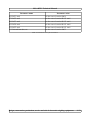
1
METRISOFT MÉRLEGGYÁRTÓ KFT
* 6800, Hódmezővásárhely Jókai u. 30.
☎ Tel.: (62) 246-657
Fax.: (62) 249-765
- Email: [email protected]
: Web: www.metrisoft.hu
Utolsó mentés: 2012-12-03
MS-ADTE1
Technical Manual
Design, construction, production, service and sale of electronic weighing equipments
36/1
MS-ADTE1 Technical Manual
Contents
1. Purpose.............................................................................................................................................4
2. Technical parameters........................................................................................................................4
3. Definition of the parameters.............................................................................................................5
3.1. Metrological parameters...........................................................................................................5
3.1.1. Resolution (number of divisions)......................................................................................5
3.1.2. One division......................................................................................................................5
3.1.3. Number of decimals..........................................................................................................5
3.1.4. Operation mode.................................................................................................................5
3.1.5. Filter table resolution........................................................................................................5
3.1.6. Hysteresis of the indication...............................................................................................5
3.1.7. Conditions of the still-stand position................................................................................6
3.1.8. Zero-point compensation range.........................................................................................6
3.1.9. Weighing frequency (sampling rate).................................................................................6
3.1.10. Zero setting at switching-on............................................................................................6
3.1.11. Still-stand needed for taring............................................................................................7
3.1.12. Range for zero setting.....................................................................................................7
3.2. Communication parameters......................................................................................................7
3.2.1. Name.................................................................................................................................7
3.2.2. Name of the display device...............................................................................................7
3.2.3. Transmission speed...........................................................................................................7
3.2.4. Parity.................................................................................................................................8
3.2.5. Number of data bits...........................................................................................................8
3.2.6. Number of stop bits...........................................................................................................8
3.2.7. Protocol.............................................................................................................................8
3.2.8. COM1 DTR listening........................................................................................................8
3.3. I/O parameters...........................................................................................................................8
3.3.1. Operation of the set-points................................................................................................8
3.3.2. Extending panel.................................................................................................................8
3.3.3. Set-point operation modes................................................................................................9
3.3.4. INPUT operation modes.................................................................................................10
3.3.5. INPUT printing form.......................................................................................................10
3.4. Data storing parameters..........................................................................................................11
3.4.1. Store mode......................................................................................................................11
3.4.2. Store location..................................................................................................................11
3.4.3. Set-point output stores....................................................................................................11
3.4.4. Storage period.................................................................................................................11
3.4.5. Time unit of storage........................................................................................................11
3.4.6. Structure of the data record.............................................................................................11
3.4.7. Power outage detection...................................................................................................12
3.5. Parameter list of the instrument..............................................................................................12
4. Configuration..................................................................................................................................15
4.1. Configuration at switching-on................................................................................................15
4.2. Configuration during operation...............................................................................................15
4.3. Means of configuration...........................................................................................................15
4.3.1. „ADTKIJ” external display device.................................................................................15
4.3.2. Computer that runs a serial testing application...............................................................15
Design, construction, production, service and sale of electronic weighing equipments
36/2
MS-ADTE1 Technical Manual
4.3.3. Computer that runs „MS_SETUP” configuration program............................................16
5. Calibration......................................................................................................................................20
5.1. „Two-knob” calibration..........................................................................................................20
5.2. Calibration by the „STW” serial testing application...............................................................21
5.3. Calibration by the „MS_SETUP” configuration program......................................................22
6. Communication protocol................................................................................................................24
6.1. Metrisoft protocol...................................................................................................................24
6.1.1. General inquiries.............................................................................................................24
6.1.2. General commands..........................................................................................................24
6.1.3. Inquiry commands of the mass........................................................................................25
6.1.4. Data storing inquiries and commands.............................................................................25
6.1.5. I/O inquiries and commands...........................................................................................27
6.1.6. Configuration inquiries and commands..........................................................................27
6.1.7. Cell under- and overload errors.......................................................................................29
6.2. Modbus protocol.....................................................................................................................30
6.2.1. Modbus inquiries.............................................................................................................30
6.2.2. Modbus commands.........................................................................................................31
6.2.3. Testing the Modbus communication with computer.......................................................31
7. Setting the analogue current output................................................................................................35
7.1. Entering the calibration of the current output.........................................................................35
7.2. Setting the zero position.........................................................................................................36
7.3. Setting the span value.............................................................................................................36
List of tables
Table 1: Parameters of the still-stand conditions..................................................................................6
Table 2: Parameters of the weighing frequencies.................................................................................6
Table 3: Parameters of the communication speed (data transfer).........................................................7
Table 4: Parameters of the parity..........................................................................................................8
Table 5: Set-point modes......................................................................................................................9
Table 6: modification of the set-poit modes ........................................................................................9
Table 7: INPUT operation modes.......................................................................................................10
Table 8: Data store modes..................................................................................................................11
Table 9: Structure of the data record..................................................................................................12
Table 10: Parameter list of the instrument..........................................................................................14
Table 11: Configuration at switching-on............................................................................................15
Table 12: General inquiries................................................................................................................24
Table 13: General commands.............................................................................................................24
Table 14: Inquiry commands of the mass...........................................................................................25
Table 15: Data storing inquiries and commands................................................................................26
Table 16: I/O inquiries, commands....................................................................................................27
Table 17: Configuration inquiries, commands...................................................................................29
Table 18: Cell under- and overload errors..........................................................................................29
Table 19: Modbus inquiries................................................................................................................30
Table 20: Modbus commands.............................................................................................................31
Table 21: Structure of the Modbus query...........................................................................................32
Table 22: Structure of the answer given to the Modbus query...........................................................33
Table 23: Structure of the Modbus command....................................................................................33
Design, construction, production, service and sale of electronic weighing equipments
36/3
MS-ADTE1 Technical Manual
1. Purpose
The MS-ADTE1 instrument's reduced dimensions and high flexibility make it possible to use in a
wide industrial range. It can be equipped with an external display unit as well.
The set-point outputs are isolated via opto-couplers and by this way they can be connected to the
control organs of the technology. The isolated analogue current output produces signal proportional
to the measured mass in form of 0..20 mA or 4..20 mA. Through the both communication interfaces
all the functions of the instrument will be available.
Attention: it is not allowed (must not) to feed the analogue current output with external power!
The analogue input of the PLC has to be used in that mode which doesn't provide voltage.
2. Technical parameters
Type number:
MS-ADTE1
Program version:
ADTE v2.2
Supply voltage:
12..24V DC
Power consumption:
2,5VA
Weighing cells:
4*350Ω
Signal range to be used:
0..2mV/V
Zero point setting:
0..2mV/V
Outputs:
5 set-point outputs isolated via opto-couplers
Inputs:
4 inputs isolated via opto-couplers
Analogue output:
Isolated 0..20mA or 4..20 mA proportional to the measured
mass
Max. load:
470Ω
Linearity:
±0.05%
Temperature error:
±0.1%/30
Communication:
RS232, RS422/485
If the load cell is equipped with 4-wire cable, then scale instrument's Sense- , Excitationconnections and Sense+ , Excitation+ connections have to be short-circuited!
Design, construction, production, service and sale of electronic weighing equipments
36/4
MS-ADTE1 Technical Manual
3. Definition of the parameters
3.1. Metrological parameters
3.1.1. Resolution (number of divisions)
It defines the resolution (number of divisions) of the scale.
Values: It can be adjusted from 100 up to 60,000 divisions by 100 steps.
3.1.2. One division
It defines the value of one scale division.
Values: 1,2,5,10,20,50,100
3.1.3. Number of decimals
It defines the number of decimals of the measured mass.
Values: 0,1,2,3,4
3.1.4. Operation mode
OMH (Hungarian Metrological Bureau): in this operation mode – according to the regulation in
force – during the calibration process the scale can set to zero within ± 2% range; furthermore under
the zero point by 9 divisions an „Underloaded”, over the span value by 9 divisions „Overloaded”
signal will be given out.
The following parameters can have only specified values:
- Range for zero setting: -1+3 , +-2
- Still-stand needed for taring: Igen
- Zero-point compensation mode:
Lassu (if weighing frequency > 12Hz), Kozepes (if weighing frequency <= 12Hz)
- One division: max. 5 (if number of decimals < 3)
- Resolution: max. 6000
- Conditions of the still-stand position: 0.3*20, 0.3*10, 0.3*5, 0.4*5, 0.5*5
Ipari (Technological mode): in this operation mode the scale can be put into zero position within
± 20% and there are no „Underloaded” and „Overloaded” signals.
3.1.5. Filter table resolution
The scale – according to the selected filter table – will use the averaging. As higher number of the
averaging shall be set as slower the weighing operation will be, but at the same time the indication
shall be more stable.
Values: It can be adjusted from 1 to 8.
3.1.6. Hysteresis of the indication
With this value we can define a range. If the high resolution mass value shall be moving within this
range, the indication will not be changed. Of course under this terminology we understand the
refreshing cycle of the normal mass value.
Values: 0, 0.1d, 0.2d, 0.3d (in division)
Design, construction, production, service and sale of electronic weighing equipments
36/5
MS-ADTE1 Technical Manual
3.1.7. Conditions of the still-stand position
Value
Definition
0.2*20
During 20 weighing cycles the changes of mass will be within 0.2 scale division
0.2*10
During 10 weighing cycles the changes of mass will be within 0.2 scale division
0.2*5
During 5 weighing cycles the changes of mass will be within 0.2 scale division
0.2*1
During 1 weighing cycle the changes of mass will be within 0.2 scale division
0.3*20
During 20 weighing cycles the changes of mass will be within 0.3 scale division
0.3*10
During 10 weighing cycles the changes of mass will be within 0.3 scale division
0.3*5
During 5 weighing cycles the changes of mass will be within 0.3 scale division
0.3*1
During 1 weighing cycle the changes of mass will be within 0.3 scale division
0.4*5
During 5 weighing cycles the changes of mass will be within 0.4 scale division
0.4*1
During 1 weighing cycle the changes of mass will be within 0.4 scale division
0.5*5
During 5 weighing cycles the changes of mass will be within 0.5 scale division
0.5*1
During 1 weighing cycle the changes of mass will be within 0.5 scale division
0.7*1
During 1 weighing cycle the changes of mass will be within 0.7 scale division
1.0*1
During 1 weighing cycle the changes of mass will be within 1.0 scale division
1.5*1
During 1 weighing cycle the changes of mass will be within 1.5 scale division
2.0*1
During 1 weighing cycle the changes of mass will be within 2.0 scale division
Table 1: Parameters of the still-stand conditions
3.1.8. Zero-point compensation mode
It is used to compensate the slow movement of zero-point of the unloaded scale.
Values: Nincs (None) , Lassu (Slow), Kozepes (Middle-speed), Gyors (Fast)
3.1.9. Weighing frequency (sampling rate)
It is defined by the sampling rate of the A/D converter of the instrument.
Value
6 Hz
12 Hz
25 Hz
50 Hz
Table 2: Parameters of the weighing frequencies
3.1.10. Zero setting at switching-on
After switching-on, the instrument will set the zero-point if the conditions are appropriate (see the
case of section 3.1.12.)
Values: Nincs (None), Probal (Try)
Design, construction, production, service and sale of electronic weighing equipments
36/6
MS-ADTE1 Technical Manual
3.1.11. Still-stand needed for taring
The taring of the scale only can be carried out if no weight movement.
Values: Nem (No), Igen (Yes)
3.1.12. Range for zero setting
Zero setting can be carried out within the given percentage of the weighing range.
Value: -1+3, +-2, +-10, +-30 (in percentage)
3.2. Communication parameters
By means of these parameters we can define the characteristics and the protocols of the
communication interfaces, their identification addresses. The COM1 is the RS232 interface (dSub9)
and the COM2 is the RS485 interface (teminal block).
3.2.1. Name
The range of the names can be used for one of the communication channels (COM1, COM2)
depends on the adjusted protocol.
In case of „Metrisoft” and „Onadas” protocol: ASCII characters between '@' and 'Z'.
In case of „Modbus” protocol: numbers (decimal) between 0 and 255.
3.2.2. Name of the display device
It determines the address where the scale will continuously send the gross weight value to, if the
protocol has been set to „Onadas” on one of the communication channels.
Values: ASCII characters between '@' and 'Z'
3.2.3. Transmission speed (Baud rate)
Here the transmission speed of the communication channel can be set.
Value (baud)
600
1200
2400
4800
9600
19200
38400
56700
115200
230400
Table 3: Parameters of the communication speed (data transfer)
Design, construction, production, service and sale of electronic weighing equipments
36/7
MS-ADTE1 Technical Manual
3.2.4. Parity
Here the parity of the communication channel can be set.
Value
Nincs (None)
Paros (Even)
Paratlan (Odd)
Table 4: Parameters of the parity
3.2.5. Number of data bits
On both communication channels 7 or 8-bit communication form can be set on.
3.2.6. Number of stop bits
The number of stop bits is set to 1 on both communication channels and it can't be adjusted.
3.2.7. Protocol
In the MS-ADT1 unit two protocols are realized. One of them is the Metrisoft Kft's own protocol,
the description of which can be found in the section of the Communication protocol (see the case
of section 6.1.). The second protocol is the MODBUS protocol. The address distribution is also can
be read in this same section (see the case of section 6.2.).
In this menu the „Onadas” and the „Nyomtatas” function can be set on as well. By using „Onadas”
the scale continuously sends the gross weight value to the previously set display address (see the
case of section 3.2.2.). The „Nyomtatas” function has to be used if a printer device is connected to
the COM1 port and we would like to print.
Values: Metrisoft, Modbus, Onadas (Independent transmission), Nyomtatas (Printing)
3.2.8. COM1 DTR listening
Values : Nincs (None) , Van (Yes)
In case of using „Nyomtatas” protocol on COM1 port and the DTR output is attached as well, this
value must be set to „Van” (Yes). In other case it must be set to „Nincs” (None).
3.3. I/O parameters
By means of these parameters we can settle the functions of the set-point outputs and the functions
of the inputs as well.
3.3.1. Operation of the set-points
By means of this parameter we can enable or disable the operation of the set-points.
Values: Nincs (None) , Van (Yes)
3.3.2. Extending panel
The MS-ADT1 unit in basic version has 2 set-point outputs, and this can an be extended using an
additional panel having 3 set-point outputs and 4 inputs. In turn, the MS-ADTE1 unit already has 5
set-point outputs and 4 inputs by default. This parameter can be found here by the relation of the
MS-ADT1 instrument, and it used to indicate the „virtual” presence of this extending panel toward
Design, construction, production, service and sale of electronic weighing equipments
36/8
MS-ADTE1 Technical Manual
the instrument. So by disabling this parameter, only 2 set-point outputs will be usable.
Values: Nincs (None) , Van (Yes)
3.3.3. Set-point operation modes
The operation mode of the set-point outputs is composed from two parts. In the first part we can
define the relation of an output with an appropriate mass value combined with other conditions. In
the second part we have a possibility to set on other characteristics as well.
Parameter value
0. Nincs (None)
Definition
The set-point output is passive
1. B>SP & OUT3=0 The output is active if the gross mass is higher than the settled value and
the output 3 is inactive
2. B>SP
The output is active if the gross mass is higher than the settled value
3. N>SP
The output is active if the net mass is higher than the settled value
4. B<SP
The output is active if the gross mass is lower than the settled value
5. N<SP
The output is active if the net mass is lower than the settled value
6. SP1<B<SP2
The output is active if the gross mass is between the value settled on the
Output1 and the value settled on the Output2
7. SP1<N<SP2
The output is active if the net mass is between the value settled on the
Output1 and the value settled on the Output2
8. B<SP & FLAG=1 The output is active if the gross mass is higher than the settled value and
the corresponding FLAG to the output is set on
9. N<SP & FLAG=1 The output is active if the net mass is higher than the settled value and the
corresponding FLAG to the output is set on
Table 5: Set-point modes
Parameter value
Definition
0. Nincs (None)
No modification
1. Nyug (Still-stand)
The output is inactive, if the mass is out of still-stand
2. 3Hz
A 3 Hz signal will appear on the output
3. Nyug, 3Hz
The two conditions are fulfilled
4. Neg (Negation)
The output is negated
5. Nyug, Neg
The two conditions are fulfilled
6. 3Hz, Neg.
The two conditions are fulfilled
7. Nyug, 3Hz, Neg.
The two conditions are fulfilled
8. ABS
The absolute mass value is considered
Table 6: modification of the set-poit modes
Design, construction, production, service and sale of electronic weighing equipments
36/9
MS-ADTE1 Technical Manual
There are 90 kinds of set-point operation modes (0..89) can be adjusted by using the upper two
tables. The required operation mode can be adjusted as follows: at first, take a value from the Table
6 and after that take a value from the Table 5 (Example: 12 = the scale is in still-stand condition and
the gross mass is higher than the settled value).
3.3.4. INPUT operation modes
The MS-ADTE1 unit is supplied by 4 inputs, the functions of them can be settled into the following
operation modes.
Parameter value
Definition
Nincs (None)
The input is passive
Nullaz (Zero setting)
The scale is zeroed in gross mode
Taraz (Taring)
In net mode the scale will be taring
Nullaz/Taraz
(Zero setting/Taring)
Performs a zero setting or a taring, depending on the current operation mode
(gross or net). So the two functions can be achieved by using only one input.
Uzemmod valt.
Switches between gross and net operation modes
(Switch operation mode)
Nyomtat (Print)
Starts to print values defined on the printing form.
Tarol (Validate)
Stores the current measuring result into the data storing buffer.
After switching off the unit, the stored data will be lost.
Tarol+Nyomtat
If the data store is succeeded, it performs the print.
(Validate+Print)
Table 7: INPUT operation modes
3.3.5. INPUT printing form
It can be set separately for the 4 inputs if which printing form will be printed out when the given
input is active. The printing forms can be sent (uploaded) to the instrument by using the program
called „MS_SETUP” and also this program is used to query (download) them from the instrument.
In the instrument, 2 different printing forms can be stored.
Values: Elso forma (First form), Masodik forma (Second form)
Design, construction, production, service and sale of electronic weighing equipments
36/10
MS-ADTE1 Technical Manual
3.4. Data storing parameters
3.4.1. Store mode
Parameter value
Definition
Nincs (None)
No data storing
Ido (Periodic)
The data store will be carried out by the given interval if the scale is in stillstand condition.
Hiba (Error)
Only the wrong weight values will be stored
Hatarertek (Set-point) The data store will be carried out on any of the active outputs
Bemenet (Input)
The data store will be carried out if the operation mode of one of the inputs is
set to „Tarol” and the given input is active.
Table 8: Data store modes
3.4.2. Store location
Values: Belso memoria (RAM memory), Flash memoria (Flash memory), Belso+Flash m.
(RAM+Flash)
Attention: after switching off the unit, all the data stored in the internal (RAM) memory will be
lost!
3.4.3. Set-point output stores
It can be set separately for the 5 inputs if data store will be performed when the given output is
active. It only takes effect if the Store mode is set to „Hatarertek” (see the case of section 3.4.1.)
Values: Nincs (None), Van (Yes)
3.4.4. Storage period
The value given here and the Time unit of storage parameter (see the case of section 3.4.1.)
together specify the time interval of the periodic data storage.
It only takes effect if the Store mode is set to „Ido” (see the case of section 3.4.1.)
3.4.5. Time unit of storage
Values: mp, perc, ora (sec, min, hour)
3.4.6. Structure of the data record
serial number date
time
code
operation mode
gross mass
net mass
The date field means the storage date, the time field means the storage time.
The value of the code field is always 0.
The operation mode field is displayed by 2 characters (xy), that can be interpreted as follows:
Examples:
Bi = data store operation performed in Gross mode, by an input signal
Nb = data store operation performed in Net mode, by active set-point Output2
Design, construction, production, service and sale of electronic weighing equipments
36/11
MS-ADTE1 Technical Manual
Character
Value
x
B, N
y
(what caused the
data store)
Definition
data store performed in Gross or Net operation mode
a
data store performed by active set-point Output1 (HAT1)
b
data store performed by active set-point Output2 (HAT2)
c
data store performed by active set-point Output3 (HAT3)
d
data store performed by active set-point Output4 (HAT4)
e
data store performed by active set-point Output5 (HAT5)
h
erroneous data store performed
i
data store performed by an active input
t
data store performed by time interval
Table 9: Structure of the data record
In the scale instrument's internal memory 20 records, in the flash memory 10000 records can be
stored. If during the data store process it reaches this record amount, then content of the first record
will be lost and the new record will get the serial number of the first record.
The value of the serial number field can be between 0 and 19, and between 0 and 9999 (the
counting starts not from 1).
3.4.7. Power outage detection
The value given here specify the level of supply voltage under which the instrument will be
switched off and over which it will be switched on.
Values: decimal numbers between 25 and 104 which mean a practical relation ratio.
25 = ~ 20V, 104 = ~ 11V.
3.5. Parameter list of the instrument
Parameter name
Parameter value
01. Felbontas
see the case of section 3.1.1.
02. Lepesnagysag
see the case of section 3.1.2.
03. Tizedesjegyek szama
see the case of section 3.1.3.
04. Nyugalom feltetel
see the case of section 3.1.7.
05. Tarazashoz nyug. kell
see the case of section 3.1.11.
06. Uzemmod
see the case of section 3.1.4.
07. Nullazasi tartomany
see the case of section 3.1.12.
08. Nullkovetesi mod
see the case of section 3.1.8.
09. Cella szurohossz
see the case of section 3.1.5.
10. Kijelzesi hiszterezis
see the case of section 3.1.6.
11. Meresi frekvencia
see the case of section 3.1.9.
12. Bekapcsolasi nullazas
see the case of section 3.1.10.
Design, construction, production, service and sale of electronic weighing equipments
36/12
MS-ADTE1 Technical Manual
Parameter name
Parameter value
13. COM1 neve
see the case of section 3.2.1.
14. COM1 baud rate
see the case of section 3.2.3.
15. COM1 paritas
see the case of section 3.2.4.
16. COM1 adatbitszam
see the case of section 3.2.5.
17. COM1 stopbitszam
see the case of section 3.2.6.
18. COM1 protokoll
see the case of section 3.2.7.
19. COM1 DTR figyeles
see the case of section 3.2.8.
20. COM2 neve
see the case of section COM1 neve
21. COM2 baud rate
see the case of section COM1 baud rate
22. COM2 paritas
see the case of section COM1 paritas
23. COM2 adatbitszam
see the case of section COM1 adatbit szam
24. COM2 stopbitszam
see the case of section COM1 stopbit szam
25. COM2 protokoll
see the case of section COM1 protokoll
26. Kijelzo neve (onadas)
see the case of section 3.2.2.
27. Hatarertek kezeles
see the case of section 3.3.1.
28. Bovitoport kezeles
see the case of section 3.3.2.
29. OUT1 uzemmod
see the case of section 3.3.3.
30. OUT2 uzemmod
see the case of section OUT1 uzemmod
31. OUT3 uzemmod
see the case of section OUT1 uzemmod
32. OUT4 uzemmod
see the case of section OUT1 uzemmod
33. OUT5 uzemmod
see the case of section OUT1 uzemmod
34. INPUT1 uzemmod
see the case of section 3.3.4.
35. INPUT2 uzemmod
see the case of section INPUT1 uzemmod
36. INPUT3 uzemmod
see the case of section INPUT1 uzemmod
37. INPUT4 uzemmod
see the case of section INPUT1 uzemmod
38. INPUT1 nyomtat. forma
see the case of section 3.3.5.
39. INPUT2 nyomtat. forma
see the case of section INPUT1 nyomtat. forma
40. INPUT3 nyomtat. forma
see the case of section INPUT1 nyomtat. forma
41. INPUT4 nyomtat. forma
see the case of section INPUT1 nyomtat. forma
42. Tarolasi mod
see the case of section 3.4.1.
43. Tarolas helye
see the case of section 3.4.2.
44. Ido mertekegyseg
see the case of section 3.4.5.
45. Tarolasi ido
see the case of section 3.4.4.
Design, construction, production, service and sale of electronic weighing equipments
36/13
MS-ADTE1 Technical Manual
Parameter name
Parameter value
46. HAT1 tarol
see the case of section 3.4.3.
47. HAT2 tarol
see the case of section HAT1 tarol
48. HAT3 tarol
see the case of section HAT1 tarol
49. HAT4 tarol
see the case of section HAT1 tarol
50. HAT5 tarol
see the case of section HAT1 tarol
51. Halozatkimaradas erz.
see the case of section 3.4.7.
Table 10: Parameter list of the instrument
Design, construction, production, service and sale of electronic weighing equipments
36/14
MS-ADTE1 Technical Manual
4. Configuration
The configuration of the instrument is performed via the COM1 or the COM2 communication
channel.
4.1. Configuration at switching-on
The „Üzemkész” LED is blinking for about 3-4 seconds when you switch on the instrument.
If you enter the configuration during this time, the „Üzemkész” LED will remain in blinking state
until exiting. The configuration at switching-on is used in case of corruption of serial
communication parameters when therefore it is impossible to make a connection to the instrument.
During the configuration at switching-on the following default serial parameter values can be used
to communicate with the instrument:
Baud rate
Parity
Data bits
Stop bits
9600 baud
None (nincs)
8
1
Table 11: Configuration at switching-on
4.2. Configuration during operation
After the configuration at switching-on is being ended (the „Üzemkész” LED is continuously
lighting) the scale instrument will work in „normal” operation mode.
At this time just the previously stored serial parameter values can be used to communicate with the
instrument and to enter the configuration.
4.3. Means of configuration
The configuration of the instrument can be done in different ways.
4.3.1. „ADTKIJ” external display device
About its usage can be read in its own user manual.
4.3.2. Computer that runs a serial testing application
It can be done by using a Windows application called „STW”, which can be downloaded from the
website of Metrisoft Kft.
The tables below section 6.1. contain the list of the queries and the commands can be used by this
application.
By the following you can read about the basic usage of this program.
4.3.2.a. Communication with the instrument
After starting the program, the edit fields of those parameters can be found on the topside of the
screen that are used to establish a connection with the scale.
These values must be adjusted the same as the scale instrument's same parameters' value for
establishing the connection:
Design, construction, production, service and sale of electronic weighing equipments
36/15
MS-ADTE1 Technical Manual
But there's an exception, and that is the „MS-Kinek” parameter which one's value can be different
from the scale address (name) and it can be the '@' address as well. It means that a connection can
be established with a scale that has any of addresses (name) and has the same serial parameter
values.
4.3.2.b. Managing the instrument
On the lower right side of the screen, an edit field can be seen that is used to input the queries and
the commands for managing the instrument via serial communication channel.
The query or the command can be sent to the instrument by using the „Küld” button:
It is possible to send more than one query at the same time by using a semicolon separator after
inputting each of the queries.
On the lower left side of the screen, a listbox can be found that contains preloaded queries and
commands.
By double-clicking on the currently selected item – without clicking on „Küld” button –
that will be sent to the scale instrument immediately. In addition the content of the listbox can be
modified at will by using these buttons on the right:
(= =>Fix, <+ +Add,<= = Change, Insert, Delete)
Below the part of the screen for serial communication setup, a listbox can be found that contains all
the queries and commands sent and also the response messages received:
The interpretation of these messages can be found in the tables below section 6.1. as well.
4.3.3. Computer that runs „MS_SETUP” configuration program
This is the most complete and the most easily usable configurating tool, and also used to edit the
printing forms, send them to the instrument or get from the instrument.
After starting the program, a window appears that
can be seen here on the left.
The printing forms will be stored in the form
directory and also the yet existing ones will be
loaded from there. Besides the configuration files
will be stored there too.
After specifying the needed path, the program's
main screen will appear by clicking on the
button.
Design, construction, production, service and sale of electronic weighing equipments
36/16
MS-ADTE1 Technical Manual
The edit fields of those parameters can be found on the topside of the screen that are used to
establish a connection with the scale.
These values must be adjusted the same as the scale instrument's same parameters' value for
establishing the connection:
But there's an exception, and that is the „Cím” parameter which one's value can be different from
the scale address (name) and it can be the '@' address as well. It means that a connection can be
established with a scale that has any of addresses (name) and has the same serial parameter values.
After setting the proper values, the „Port nyitás” checkbox must be checked for establishing the
connection. In case of a problem during access to the scale, a warning message will appear.
4.3.3.a. Setting the instrument
The managing of the instrument's parameters can be done on the following screen by clicking on the
button:
The
button is used to enter the configuration and read the parameters from the
instrument.
The parameters of the instrument are sorted into different groups. You can switch between these
groups by using this tool here on the right:
Design, construction, production, service and sale of electronic weighing equipments
36/17
MS-ADTE1 Technical Manual
After setting the values of the needed parameters, the
button is used to upload
them to the instrument and also exit from both configurating modes.
Besides there's a possibility for saving the adjusted parameters into a configuration file by clicking
on the
button and also loading them from the configuration file by clicking on the
button. This procedure can be useful if the settings get corrupted in the instrument for some reason,
but of course it can be used in other cases.
The new configuration file can be named in the combobox that can be seen below and also this is
used to select the yet existing and loadable configuration file:
4.3.3.b. Printing forms
The managing of the printing forms can be done on the following screen by clicking on the
button:
In MS-ADT1 instrument, 2 different printing forms can be stored. These forms can be placed in the
0. and 1. form containers. A printing form can be assigned to a container on the following part of
the screen:
In case of a non-existing printing form, the name of the new file can be input in this combobox and
also this is used to specify the file name which the form will be stored to, at quering (downloading)
Design, construction, production, service and sale of electronic weighing equipments
36/18
MS-ADTE1 Technical Manual
the form from the instrument.
The window below will appear by clicking on the
button. This window is used to
edit and store that printing form on the computer which has the checkbox in checked state (A or B):
The window above has an edit box that is used to specify the appearance of the printig form.
By giving any constant text content, it is possible to insert variable fields too, which have changing
values during operation of the program (Examples: serial number, mass values, date).
The variables are marked with a „#” sign and can be selected from this checkbox here below:
Thereafter the cursor has to be positioned to the printing location in the edit box, and the variable
can be inserted there by clicking on the
gomb.
After editing, the
button is used to save the completed printing form to a text file which
name can be specified in the „Fájlnév” field. An alert message will appear if the given file name
already exists or the window gets closed without saving.
After that, the main screen will appear again where the saved printing forms can be uploaded to the
instrument's form containers by clicking on the
button.
The
button is used to download the printing forms – if there are any – from the
instrument and store them on the computer in the specified files.
4.3.3.c. Managing the instrument
The screen below is used to input the queries and the commands by using the combo boxes for
managing the instrument via serial communication channel.
The
button is used to appear the screen below.
These combo boxes contain preloaded values, but it is possible to modify the contents of the input
Design, construction, production, service and sale of electronic weighing equipments
36/19
MS-ADTE1 Technical Manual
fields which are needed by using some queries and commands.
The tables below section 6.1. contain the list of the queries and the commands can be used.
The content of „Parancs” combox can be sent to the instrument by using the
button.
The content of „Kérdés” combobox can be sent to the instrument by using the
button.
The response messages received from the queries and the commands will be displayed in the
„Válasz” fields, next to the two buttons. The interpretation of these messages can be found in the
tables below section 6.1. as well.
Here's a possibility for exiting the configuration without loading the parameter values into the
instrument.
This can be done by sending the
command to the instrument.
5. Calibration
The calibration of the instrument can be made by two different ways. Before the calibration it is
necessary to configure the instrument's metrological parameters! (see the case of section 4.)
5.1. „Two-knob” calibration
This procedure can be done by using the knobs (see the case of section 7.) which are used to set the
current output.
5.1.1. Entering the calibration
At switching on the instrument the „Fel” and „Le” knobs must be pressed and held for about 3
seconds. After this, the „Nulla” LED and the „Végérték” LED starts blinking alternately.
Design, construction, production, service and sale of electronic weighing equipments
36/20
MS-ADTE1 Technical Manual
5.1.2. Storing the zero value
Be sure that load receiving mechanism is empty and the scale is in the still-stand condition.
After that, the „Fel” knob must be pressed which causes that the „Nulla” LED will start lighting
continuously, the „Végérték” LED will remain in blinking state and the zero value will be stored.
5.1.3. Storing the span value
After storing the zero value, be sure that scale is in still-stand condition and put on the load of
calibration mass - that corresponds to the nominal span value - on the load receiving mechanism.
After that, the „Le” knob must be pressed which causes that the „Végérték” LED will start lighting
continuously as well and the span value will be stored.
5.1.4. Exiting the calibration
Before storing: the „Start” knob must be pressed, directly after entering the calibration. At this time
zero value and span value will not be stored in the instrument.
After storing: the „Start” knob must be pressed after storing the span value.
After exiting the „two-knob” calibration, the instrument's program will automatically start working.
5.2. Calibration by the „STW” serial testing application
5.2.1. Entering the calibration
This can be done by the way described at the Managing the instrument section (see the case of
section 4.3.2.b.) of the manual. The „CONF” command must be sent so to the instrument.
5.2.2. Storing the zero value
Be sure that load receiving mechanism is empty and the scale is in the still-stand condition.
After that, the „ZERO” command must be sent to the instrument by the way described at the
Managing the instrument section (see the case of section 4.3.2.b.) which causes that the zero
value will be stored in the instrument.
It is necessary to store the zero value at least once. At later time if its value is the same, it is enough
to re-calibrate the span value only.
5.2.3. Storing the span value
This procedure must be done after storing the zero value!
If we have at our disposal the calibration mass that corresponds to the nominal span value, then this
load must be put on the load receiving mechanism and must be waited until the scale gets into stillstand condition.
After that, the „VEG” command must be sent to the instrument by the way described at the
Managing the instrument section (see the case of section 4.3.2.b.) which causes that the span
value will be stored in the instrument.
Design, construction, production, service and sale of electronic weighing equipments
36/21
MS-ADTE1 Technical Manual
If we don't have the requested calibration mass that corresponds to the nominal span value, then it is
possible to calibrate by partial mass (the available calibration mass).
At this time the program automatically calculates the cell signal value that belongs to the nominal
span value.
The available calibration mass load must be put on the load receiving mechanism and must be
waited until the scale gets into still-stand condition.
After that, the „RVEG=” command must be sent to the instrument by the way described at the
Managing the instrument section (see the case of section 4.3.2.b.). Before sending, the available
mass value must be input after the equal sign („=”) (Example: RVEG=100) This causes that the
span value will be stored in the instrument.
5.2.4. Exiting the calibration
The „ENDPAR” command must be sent to the instrument by the way described at the Managing
the instrument section (see the case of section 4.3.2.b.).
5.3. Calibration by the „MS_SETUP” configuration program
5.3.1. Entering the calibration
The
button is used to read the parameters from the instrument and also enter the
calibration.
The other option to enter the calibration is the following:
the
command must be sent to the instrument by the way described at
the Managing the instrument section (see the case of section 4.3.3.c.).
5.3.2. Storing the zero value
Be sure that load receiving mechanism is empty and the scale is in the still-stand condition.
After that, the
command must be sent to the instrument by the way
described at the Managing the instrument section (see the case of section 4.3.3.c.) which causes
that the zero value will be stored in the instrument.
It is necessary to store the zero value at least once. At later time if its value is the same, it is enough
to re-calibrate the span value only.
5.3.3. Storing the span value
This must be done after storing the zero value!
If we have at our disposal the calibration mass that corresponds to the nominal span value, then this
load must be put on the load receiving mechanism and must be waited until the scale gets into stillstand condition.
After that, the
command must be sent to the instrument by the way
described at the Managing the instrument section (see the case of section 4.3.3.c.) which causes
that the span value will be stored in the instrument.
Design, construction, production, service and sale of electronic weighing equipments
36/22
MS-ADTE1 Technical Manual
If we don't have the requested calibration mass that corresponds to the nominal span value, then it is
possible to calibrate by partial mass (the available calibration mass).
At this time the program automatically calculates the cell signal value that belongs to the nominal
span value.
The available calibration mass load must be put on the load receiving mechanism and must be
waited until the scale gets into still-stand condition.
After that, the
command must be sent to the instrument by the way
described at the Managing the instrument section (see the case of section 4.3.3.c.). Before
sending, the available mass value must be input after the equal sign („=”) (Example: RVEG=100)
This causes that the span value will be stored in the instrument.
5.3.4. Exiting the calibration
The
command must be sent to the instrument by the way described
at the Managing the instrument section (see the case of section 4.3.3.c.).
Design, construction, production, service and sale of electronic weighing equipments
36/23
MS-ADTE1 Technical Manual
6. Communication protocol
All the inquiries and commands will be started by the marker of the inquirer, the next character will
be the name of the instrument followed by the „/” separating character. After these characters the
actual inquiry or command will appear. All the messages should be closed by the „0Dh0Ah”
characters.
The first character of the response is the name of the instrument followed by the mark of the
inquirer and the separating character and finally the actual answer will appear. All the messages
should be closed by the „0Dh0Ah” characters.
6.1. Metrisoft protocol
6.1.1. General inquiries
Inquiry
Definition
Response
Definition
XA/VER?
Inquiring the firmware version
AX/VER=x
x=version number
XA/M?
Inquiring the operation mode of the
instrument
AX/M=x
XA/MV?
Inquiring the weighing cell signal
AX/MV=x
x=cell signal (mV)
XA/FB?
Inquiring the high resolution mass value
AX/FB=x
x=high resolution mass
value
x=B, Gross mode
x=N, Net mode
Table 12: General inquiries
6.1.2. General commands
Command
Definition
Response
Definition
The taring was performed
XA/TA
XA/NU
XA/NT
Taring in Net operation mode
Zero setting in Gross operation mode
The taring can not be
performed
The zero setting was
performed
AX/OK
The zero setting can not be
performed
AX/NACK
Performed
Switching to Net operation mode
The command can not be
performed
Performed
XA/BR
Switching to Gross operation mode
The command can not be
performed
Table 13: General commands
Design, construction, production, service and sale of electronic weighing equipments
36/24
MS-ADTE1 Technical Manual
6.1.3. Inquiry commands of the mass
Inquiry
XA/B?
Definition
Inquiring the gross mass
Response
Definition
AX/B=1000
The gross mass: 1000Kg
AX/B=1000S
S=still-stand
AX/B=0SF
F=fine zero
XA/N?
Inquiring the net mass
AX/N=1000
The net mass: 1000Kg
XA/T?
Inquiring the tare value
AX/T=100
The tare value: 100Kg
Table 14: Inquiry commands of the mass
6.1.4. Data storing inquiries and commands
Inquiry, comm.
Definition
XA/DEF
Emptying the storing buffer in
the RAM memory, the stored
data records will be lost. It has
to be performed once before
the start of data storing!
XA/FDEF
Emptying the storing buffer in
the flash memory, the stored
data records will be lost. It has
to be performed once before
the start of data storing!
XA/ELS?
Stepping to the first data
record of the storing buffer in
the RAM memory
XA/AKT?
Inquiring the current data
record of the storing buffer in
the RAM memory
XA/KOV?
Stepping to the next data
record of the storing buffer in
the RAM memory
XA/FELS?
Stepping to the first data
record of the storing buffer in
the flash memory
XA/FAKT?
Inquiring the current data
record of the storing buffer in
the flash memory
XA/FKOV?
Stepping to the next data
record of the storing buffer in
the flash memory
Response
Definition
AX/OK
Performed
a=serial number
b=date (not interpreted)
c=time (not interpreted)
d=code (always 0)
AX/BUF:
e=operation mode (B,N)
a,b,c,d,e,f,g
f=gross mass
g=net mass
empty buffer
a=serial number
b=storage date
c=storage time
AX/BUF:---
d=code (always 0)
e=operation mode (B,N)
f=gross mass
g=net mass
empty buffer
Design, construction, production, service and sale of electronic weighing equipments
36/25
MS-ADTE1 Technical Manual
Inquiry, comm.
XA/RPOI?
XA/RPOI=x
Definition
Inquiring the current record
number of the read pointer
Setting the read pointer to the
record number to read from.
Response
Definition
AX/RPOI=x
x=record number to read
from
AX/OK
Performed
x=record number to write to
x=record number to read from
XA/WPOI?
Inquiring the current record
number of the write pointer
AX/WPOI=x
XA/SMOD?
Inquiring the setting of the
data store mode
AX/PAR:x=y
XA/SMOD=x
Setting the data store mode,
x=value of the store mode
(0..3)
XA/STIME?
Inquiring the value of the data
AX/STIME=x,y
store timer
Setting the value of the data
store timer.
x=time interval of the periodic
XA/STIME=x,y data storage,
y=time unit (s, m, h)
x=”42. Tarolasi mod”,
y=value of store mode
(Example: „00. Nincs”)
The command can not be
performed
AX/NACK
x=time interval of the
periodic data storage,
y= time unit (s, m, h)
AX/OK
Performed
AX/INV
Invalid parameter value
(Example: XA/STIME=5,s)
XA/SHTx?
XA/SHTx=y
Data storing in case of active
set-point output. Inquiring the
state. x=serial number of the
set-point output (1..5)
Data storing in case of active
set-point output. Setting the
state. x=serial number of the
set-point output (1..5),
y=value of the storing state
(0..1)
x=serial number of the setpoint output (1..5),
AX/SHTx=y
y=value of the storing state
(0..1)
AX/OK
Performed
AX/INVPAR
Invalid parameter value
AX/INV
Invalid set-point output serial
number
Table 15: Data storing inquiries and commands
Design, construction, production, service and sale of electronic weighing equipments
36/26
MS-ADTE1 Technical Manual
6.1.5. I/O inquiries and commands
Inquiry,
command
Definition
Response
Definition
x=status of the outputs
H=active, L=inactive
Inquiring the I/O state
XA/SP?
AX/SP=xxxxxyyyy
y=status of the inputs,
0,2,4,6,8: inactive
1,3,5,7,9: active
x=set-point output serial number
y=1, inquiring the set-point
operation mode (section 3.3.3.)
XA/HTxy?
x=serial number of the setpoint output (1..5)
AX/HTxy=value
y=2, inquiring the mass value
y=2, mass value
y=3, inquiring the FLAG
y=3, FLAG status
x=set-point output serial number
XA/HTxy=
érték
y=1, set-point oper. mode
y=1, setting the set-point mode
(section 3.3.3.)
AX/OK
Performed
Note: if the given set-point
value is higher than the
nominal final value, set-point
will be adjusted to final value
y=2, setting the mass value
y=3, setting the FLAG
Table 16: I/O inquiries, commands
6.1.6. Configuration inquiries and commands
Inquiry, comm.
Definition
Entering the manual parameter
XA/MANPAR setup. The parameter values can
be queried only.
XA/CONF
Entering the configuration.
The parameter values can be
queried and modified as well.
Response
Definition
AX/OK
Performed
AX/NACK
The command can not be
performed
AX/PAR:x=y
x=parameter name,
y=parameter value
XA/AKTPAR? Inquiring the current parameter
XA/KOVPAR Stepping to the next parameter
XA/ELOPAR
Stepping to the previous
parameter
XA/FELPAR
Increasing the value of the
current parameter
XA/LEPAR
Decreasing the value of the
current parameter
AX/NACK
The command can not be
performed
XA/ELSOPAR Jumping to the first parameter
Design, construction, production, service and sale of electronic weighing equipments
36/27
MS-ADTE1 Technical Manual
Inquiry, comm.
Definition
Setting the parameter values to
default („factory” setup). It's
XA/DEFAULT usually used at startupconfiguration in case of
parameter corruption.
Response
AX/OK
AX/NACK
Definition
Performed
The command can not be
performed
XA/ALLPAR? Listing all of the parameters
Stepping to the given parameter
XA/PARSZ=x number.
x=parameter number
XA/PAR=x
Setting the parameter's value
directly. For certain parameters
only (resolution)
AX/PAR:x=y
x=parameter name,
y=parameter value
AX/NACK
The command can not be
performed
AX/OK
Performed
AX/NACK
The command can not be
performed
x=value of parameter
XA/ZERO
XA/VEG
XA/RVEG=x
Storing the zero value for
calibration
Storing the span value for
calibration
Calibrating on the given partial
span value.
x=the calibration mass (kg)
XA/FELB?
XA/FELB=x
Inquiring the value of the
resolution directly.
Setting the value of the
resolution directly.
x=value of the resolution
XA/NEV1?
XA/NEV2?
Inquiring the name of COM1 or
COM2 directly
XA/NEV1=x
Setting the name of COM1 or
COM2 directly.
XA/NEV2=x
XA/KNEV?
AX/PAR:x=y
x=name of COM1 or COM2
(Example: XA/NEV1=A)
AX/NACK
AX/PAR:x=y
x=”01. Felbontas”,
y=value of the resolution
The command can not be
performed
x=”13. COM1 neve”,
x=”20. COM2 neve”,
y=name ('@'..'Z' or 0..255)
AX/NACK
Inquiring the name of the display
AX/PAR:x=y
device directly
The command can not be
performed
x=”26. Kijelzo neve
(onadas)”,
y=name ('@'..'Z')
XA/KNEV=x
Setting the name of the display
device directly
x=name of the display device
AX/NACK
The command can not be
performed
Design, construction, production, service and sale of electronic weighing equipments
36/28
MS-ADTE1 Technical Manual
Inquiry, comm.
XA/IDO?
Definition
Inquiring the current date and
time. It is recommended to check AX/IDO=x,y
these values before data store.
Setting the current date and time.
It is recommended to perform
this operation before data store.
XA/IDO=x,y
Response
x=year.month.day
(year contains 2 digits!)
y=hour:minute:second
Definition
x=year.month.day
y=hour:minute:second
AX/OK
Performed
AX/INV
Invalid parameter value
AX/PAR:x=y
x=”51. Halozatkimaradas
erz.”,
(Example:
XA/IDO=11.01.01,08:00:00)
XA/HALKI?
Inquiring the value of the power
outage detection directly
Setting the value of the power
XA/HALKI=x outage detection directly.
x=value (section 3.4.7.)
XA/ENDPAR
Exiting the manual parameter
setup or configuration
XA/SAVEPAR
Saving the modified parameters
in configuration
y=value
AX/OK
Performed
AX/NACK
The command can not be
performed
Table 17: Configuration inquiries, commands
6.1.7. Cell under- and overload errors
If the value of the Operation mode parameter (see the case of section 3.1.4.) is set to „OMH”, the
scale can indicate the following error messages depending on the scale's load.
Value
Definition
ERROR2
Scale (cell) is extremly underloaded (over zero point - 9 divisons)
ERROR3
Scale (cell) is extremly overloaded (over span value + 9 divisions)
ERROR4
Scale (cell) is underloaded (until zero point - 9 divisions)
ERROR5
Scale (cell) is overloaded (until span value + 9 divisions)
Table 18: Cell under- and overload errors
Design, construction, production, service and sale of electronic weighing equipments
36/29
MS-ADTE1 Technical Manual
6.2. Modbus protocol
6.2.1. Modbus inquiries
Memory address (0x)
Denomination
Size
01
Set-point Output1 switching value
2 words
Example: 01 03 00 01 00 02
03
Set-point Output2 switching value
2 words
05
Set-point Output3 switching value
2 words
07
Set-point Output4 switching value
2 words
09
Set-point Output5 switching value
2 words
0B
Status bits:
1 word
bit 0: unused (always 0)
bit 1: Still-stand
bit 2: Cell overload
bit 3: Cell underload
bit 4: Output1 status
bit 5: Output2 status
bit 6: Output3 status
bit 7: Output4 status
bit 8: Output5 status
bit 9: Input1 status
bit 10: Input2 status
bit 11: Input3 status
bit 12: Input4 status
bit 13: Operation mode (0 = Gross, 1 = Net)
0C
Number of decimals
1 word
0D
Gross mass value
2 words
0F
Net mass value
2 words
11
Tare value
2 words
Table 19: Modbus inquiries
Note: the number of decimals specify the interpretation of mass values.
Example:
The gross mass value by querying = 1390kg, the number of decimals = 2
The real gross mass value = 1390 / (10^2) = 1390 / 100 = 13.90kg
Design, construction, production, service and sale of electronic weighing equipments
36/30
MS-ADTE1 Technical Manual
6.2.2. Modbus commands
Memory address (0x)
Denomination
Size
01, 03, 05, 07, 09
Setting the switching values of the set-point outputs
2 words
Example:
set-point Output1: 01 10 00 01 00 02 04 00 01 38 80
0B
Switching between gross and net operation modes
1 word
Allowed values: 0 (Gross), 1 (Net)
Example:
switching to Net mode: 01 06 00 0B 00 01
13
Zero setting in Gross mode or taring in Net mode
1 word
Allowed values: 0 (Zero setting), 1 (Taring)
Example:
taring in Net operation mode: 01 10 00 13 00 01 02 00 01
Table 20: Modbus commands
6.2.3. Testing the Modbus communication with computer
For testing, the previously described „STW” serial testing application (see the case of section 4.3.2.)
can be used as well. Of course, it can be done if the protocol has been set to MODBUS on one of
the communication channels.
Similarly to „Metrisoft” protocol, the parameters of serial communication have to be set first.
After that, on the picture can be seen on the lower left, the lowermost „Mbus” element has to be
selected from the combobox named „MS-Kinek”, which contains the scale addresses.
By doing so, the „MS-Kinek” label's name changes to „MB-Kinek”, and the combobox will
contain MODBUS addresses (decimal values). Here the address has to be selected that is specified
at the Configuration section (see the case of section 4.).
The comboboxes named „Küldő”, „Elv.jel”, „Adás záró” and „Vétel záró” will be disabled,
theirs set values will be ignored by the program. This case can be seen down on the middle picture.
After that, on the picture can be seen on the lower right, the value of the „Kijelzés” checkbox has to
be set to „Hexa” in order that sent and the received values be readable.
6.2.3.a. Sending a Modbus inquiry
Similarly to „Metrisoft” protocol, on the lower right side of the screen, an edit field can be seen that
is used to input the MODBUS queries and commands. The query or the command can be sent to the
instrument by using the „Küld” button.
Design, construction, production, service and sale of electronic weighing equipments
36/31
MS-ADTE1 Technical Manual
The next picture is showing an example of sending a MODBUS query, that is used to query the
gross mass value from the scale instrument:
Structure of the query:
The query has a size of 8 bytes. Each byte has to be separated by a „#” sign in the input field.
byte nr.
Definition
byte 1
The address of the scale instrument, but it doesn't have to be specified in the input
field because it can be selected from the above-mentioned MB-Kinek combobox.
In the example above, its value is 0x01.
byte 2
The MODBUS read function code (read holding registers).
Its value is 0x03.
byte 3
The address of the first register requested (upper byte).
Its value is always 0x00 by using this version of the instrument program.
byte 4
The address of the first register requested (lower byte).
Its values can be the memory addresses found in the table below section 6.2.1.
In the example above, its value is 0x0D (gross mass).
byte 5
The total number of registers requested (upper byte).
Its value is always 0x00 by using this version of the instrument program.
byte 6
The total number of registers requested (lower byte).
If you want to get the value of the first requested register only then its value is always
0x01. The maximum number of the registers can be requested is dependent on the
register number (memory address) where the query begins.
By using this version of the instrument program and the table below section 6.2.1.,
this value can be 0x12 if the query begins from the 0x01 memory address.
In the example above, its value is 0x02.
byte 7 & 8 The cyclic redundancy check (CRC) for error checking.
It's automatically generated by the program, so it doesn't have to be specified.
Table 21: Structure of the Modbus query
Stucture of the answer:
Similarly to „Metrisoft” protocol, below the part of the screen for serial communication setup, a
listbox can be found that contains the queries sent (with brown background) and also the response
messages received (with green background):
Design, construction, production, service and sale of electronic weighing equipments
36/32
MS-ADTE1 Technical Manual
Denomination
Size
Device address
1 byte
It's the same as the device address sent in the query.
In the example above, its value is 0x01.
Function code
1 byte
0x03
Byte number
1 byte
2*n (n=the number of registers requested)
In the example above, its value is 0x04.
Register value
Cyclic redundancy
check (CRC)
Value
n*2 bytes The value(s) found on the requested memory address(es).
In the example above the gross mass = 0x00000F02 (3842 kg),
if the number of decimals = 0.
2 bytes
It's automatically generated by the program.
Table 22: Structure of the answer given to the Modbus query
6.2.3.b. Sending a Modbus command
The next picture is showing an example of sending a MODBUS command, that is used to switch the
instrument to net operation mode:
Structure of the command:
The command has a size of 8 bytes. Each byte has to be separated by a „#” sign in the input field.
byte nr.
Definition
byte 1
The address of the scale instrument, but it doesn't have to be specified in the input
field because it can be selected from the above-mentioned MB-Kinek combobox.
In the example above, its value is 0x01.
byte 2
The MODBUS write function code (preset single register).
Értéke 0x06.
byte 3
The address of the register written (upper byte).
Its value is always 0x00 by using this version of the instrument program.
byte 4
The address of the register written (lower byte).
Its values can be those memory addresses found in the table below section 6.2.2.,
which values don't have to be assigned on 2 words (4 bytes).
In the example above, its value is 0x0B (switch operation mode).
byte 5
The value to write to the register (upper byte).
In the example above, its value is 0x00.
byte 6
The value to write to the register (lower byte).
In the example above, its value is 0x01.
byte 7 & 8 The cyclic redundancy check (CRC) for error checking.
It's automatically generated by the program, so it doesn't have to be specified.
Table 23: Structure of the Modbus command
Design, construction, production, service and sale of electronic weighing equipments
36/33
MS-ADTE1 Technical Manual
Note: it is possible to write more than one registers at the same time by using the 0x10 MODBUS
function code (preset multiple registers). Of course, in this case the structure of the command differs
from the description that can be found in the previous table.
Stucture of the answer:
Similarly to „Metrisoft” protocol, below the part of the screen for
serial communication setup, a listbox can be found that contains
the queries sent (with brown background) and also the response
messages received (with green background).
By default, the structure of the respone message is the same as the structure of the command, so we
get back what we send to the instrument.
Design, construction, production, service and sale of electronic weighing equipments
36/34
MS-ADTE1 Technical Manual
7. Setting the analogue current output
Before setting the current output it is necessary to calibrate the instrument as scale (see the case of
section 5.). After doing so, the needed current value can be assigned to the cell signal values that
correspond to the zero value and the span value.
7.1. Entering the calibration of the current output
Entering the calibration of the current output is not allowed if the instrument is in the configuration!
SenseExcitation-
Sense+
Excitation+
Signal+
Signall-
RS485
Power input
12..24V DC
Load cell
R+/D+
R-/D-
„Start” knob:
- Entering the calibration
- Storing the calibration values
- Exiting calibration
Set-point
OUTPUT1
-
Press and hold the „Start” knob for about 4-5 seconds.
When the „Nulla” („Zero”) LED will be illuminated, then release the „Start” knob.
By these operations you can enter the zero position setting of the calibration function.
Set-point
OUTPUT 2
-
„Végérték”
(„Span value”)
LED
„Nulla” („Zero”)
LED
„Le” („Down”) knob:
Current value decreasing
„Fel” („Up”) knob:
Current value increasing
Set-point 2
activity LED
Set-point 1
activity LED
Operation ready
LED
Still-stand
activity LED
Design, construction, production, service and sale of electronic weighing equipments
36/35
MS-ADTE1 Technical Manual
7.2. Setting the zero position
-
By using the „Fel” („Up”) and the „Le” („Down”) knobs you can set the current value (0mA or
4mA) corresponding to the mass zero value.
-
To store this value, press and hold the „Start” knob while the „Nulla” („Zero”) LED will be
switched-off and the „Végérték” („Span value”) LED will be illuminated.
By doing so, you enter the span value setting.
!
If the „Up” or the „Down” knobs will not be depressed and we shall follow to
press the „Start” knob to set the span value, then the zero
point value in the instrument shall not be changed!
7.3. Setting the span value
-
By using the „Fel” („Up”) and the „Le” („Down”) knobs you can set the current value (20mA)
corresponding to the mass span value.
-
Press and hold the „Start” knob while the „Végérték” („Span value”) LED will be switchedoff. By doing so, you exit the calibration function.
!
If the „Up” and the „Down” knobs will not be depressed, then
the span value in the instrument shall not be changed!
Design, construction, production, service and sale of electronic weighing equipments
36/36