1
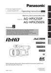
Memory Card Camera-Recorder Model No. 1 Menu Volume AG-HPX250P AG-HPX250EN Reference Note that Operation Instructions Vol. 1 describes basic operations of the Memory Card Camera-Recorder. For instructions on advanced operations of the Memory Card Camera-Recorder, refer to Operating Instructions Vol. 2 (pdf file) contained in the supplied CD-ROM. Before operating this product, please read the instructions carefully and save this manual for future use. SS0811HO0 -FJ Printed in Japan Before use Vol.1 Description of parts Operating Instructions Preparation ■ This product is eligible for the P2HD 5 Year Warranty Repair Program. For details, see page 8. ENGLISH VQT3T24 Read this first! (For AG-HPX250P) indicates safety information. CAUTION RISK OF ELECTRIC SHOCK DO NOT OPEN CAUTION: TO REDUCE THE RISK OF ELECTRIC SHOCK, DO NOT REMOVE COVER (OR BACK). NO USER-SERVICEABLE PARTS INSIDE. REFER TO SERVICING TO QUALIFIED SERVICE PERSONNEL. The lightning flash with arrowhead symbol, within an equilateral triangle, is intended to alert the user to the presence of uninsulated “dangerous voltage” within the product’s enclosure that may be of sufficient magnitude to constitute a risk of electric shock to persons. The exclamation point within an equilateral triangle is intended to alert the user to the presence of important operating and maintenance (servicing) instructions in the literature accompanying the appliance. WARNING: This equipment must be grounded. To ensure safe operation, the three-pin plug must be inserted only into a standard threepin power outlet which is effectively grounded through normal household wiring. Extension cords used with the equipment must have three cores and be correctly wired to provide connection to the ground. Wrongly wired extension cords are a major cause of fatalities. The fact that the equipment operates satisfactorily does not imply that the power outlet is grounded or that the installation is completely safe. For your safety, if you are in any doubt about the effective grounding of the power outlet, please consult a qualified electrician. WARNING: Do not jar, swing, or shake the unit by its handle. Any strong jolt to the handle may damage the unit or result in personal injury. CAUTION: The mains plug of the power supply cord shall remain readily operable. The AC receptacle (mains socket outlet) shall be installed near the equipment and shall be easily accessible. To completely disconnect this equipment from the AC mains, disconnect the power cord plug from the AC receptacle. CAUTION: Danger of explosion or fire if battery is incorrectly replaced or mistreated. • Do not disassemble the battery or dispose of it in fire. • Do not store in temperatures over 60°C (140°F). • Do not expose the battery to excessive heat such as sunshine, fire or the like. For Battery Pack • Use specified charger. • Replace only with same or specified type. For Battery of Remote Controller • Replace battery with part No. CR2025 only. • Do not recharge the battery. CAUTION: In order to maintain adequate ventilation, do not install or place this unit in a bookcase, built-in cabinet or any other confined space. To prevent risk of electric shock or fire hazard due to overheating, ensure that curtains and any other materials do not obstruct the ventilation. • To reduce the risk of fire or electric shock, do not expose this equipment to rain or moisture. • To reduce the risk of fire or electric shock hazard, keep this equipment away from all liquids. Use and store only in locations which are not exposed to the risk of dripping or splashing liquids, and do not place any liquid containers on top of the equipment. Do not lift the unit by its handle while the tripod is attached. When the tripod is attached, its weight will also affect the unit’s handle, possibly causing the handle to break and hurting the user. To carry the unit while the tripod is attached, take hold of the tripod. WARNING: CAUTION: Always keep memory cards (optional accessory) or accessories (coin battery, microphone holder screws, microphone holder adapter, INPUT terminal covers) out of the reach of babies and small children. CAUTION: To reduce the risk of fire or electric shock and annoying interference, use the recommended accessories only. 2 CAUTION: CAUTION: Excessive sound pressure from earphones and headphones can cause hearing loss. CAUTION: Do not leave the unit in direct contact with the skin for long periods of time when in use. Low temperature burn injuries may be suffered if the high temperature parts of this unit are in direct contact with the skin for long periods of time. When using the equipment for long periods of time, make use of the tripod. Read this first! (For AG-HPX250P) (continued) indicates safety information. CAUTION: This apparatus can be operated at a voltage in the range of 100 – 240 V AC. Voltages other than 120 V are not intended for U.S.A. and Canada. Operation at a voltage other than 120 V AC may require the use of a different AC plug. Please contact either a local or foreign Panasonic authorized service center for assistance in selecting an alternate AC plug. FCC NOTICE (USA) Declaration of Conformity Model Number: AG-HPX250P Trade Name: Panasonic Responsible Party: Panasonic Corporation of North America One Panasonic Way, Secaucus, NJ 07094 Support contact: 1-800-524-1448 This device complies with Part 15 of the FCC Rules. Operation is subject to the following two conditions: (1) This device may not cause harmful interference, and (2) this device must accept any interference received, including interference that may cause undesired operation. To assure continued compliance, follow the attached installation instructions and do not make any unauthorized modifications. CAUTION: This equipment has been tested and found to comply with the limits for a Class B digital device, pursuant to Part 15 of the FCC Rules. These limits are designed to provide reasonable protection against harmful interference in a residential installation. This equipment generates, uses and can radiate radio frequency energy and, if not installed and used in accordance with the instructions, may cause harmful interference to radio communications. However, there is no guarantee that interference will not occur in a particular installation. If this equipment does cause harmful interference to radio or television reception, which can be determined by turning the equipment off and on, the user is encouraged to try to correct the interference by one of the following measures: • Reorient or relocate the receiving antenna. • Increase the separation between the equipment and receiver. • Connect the equipment into an outlet on a circuit different from that to which the receiver is connected. • Consult the dealer or an experienced radio/TV technician for help. The user may find the booklet “Something About Interference” available from FCC local regional offices helpful. FCC Warning: To assure continued FCC emission limit compliance, follow the attached installation instructions and the user must use only shielded interface cables when connecting to host computer or peripheral devices. Also any unauthorized changes or modifications to this equipment could void the user's authority to operate this device. NOTIFICATION (Canada) This class B digital apparatus complies with Canadian ICES-003. Cet appareil numéique de la classe B est conforme à la norme NMB-003 du Canada. Note: Battery Charger / AC Adaptor The rating plate is on the underside of the Battery Charger and AC Adaptor. Disconnect the AC mains plug from the AC mains socket when not in use. 3 Read this first! (For AG-HPX250P) (continued) IMPORTANT SAFETY INSTRUCTIONS 1)Read these instructions. 2)Keep these instructions. 3)Heed all warnings. 4)Follow all instructions. 5)Do not use this apparatus near water. 6)Clean only with dry cloth. 7)Do not block any ventilation openings. Install in accordance with the manufacturer’s instructions. 8)Do not install near any heat sources such as radiators, heat registers, stoves, or other apparatus (including amplifiers) that produce heat. 9)Do not defeat the safety purpose of the polarized or grounding-type plug. A polarized plug has two blades with one wider than the other. A grounding-type plug has two blades and a third grounding prong. The wide blade or the third prong are provided for your safety. If the provided plug does not fit into your outlet, consult an electrician for replacement of the obsolete outlet. 10) Protect the power cord from being walked on or pinched particularly at plugs, convenience receptacles, and the point where they exit from the apparatus. 11) Only use attachments/accessories specified by the manufacturer. 12) Use only with the cart, stand, tripod, bracket, or table specified by the manufacturer, or sold with the apparatus. When a cart is used, use caution when moving the cart/ apparatus combination to avoid injury from tip-over. 13) Unplug this apparatus during lightning storms or when unused for long periods of time. 14) Refer all servicing to qualified service personnel. Servicing is required when the apparatus has been damaged in any way, such as power-supply cord or plug is damaged, liquid has been spilled or objects have fallen into the apparatus, the apparatus has been exposed to rain or moisture, does not operate normally, or has been dropped. A lithium ion/polymer battery that is recyclable powers the product you have purchased. Please call 1-800-8-BATTERY for information on how to recycle this battery. For USA-California Only This product contains a CR Coin Cell Lithium Battery which contains Perchlorate Material – special handling may apply. See www.dtsc.ca.gov/hazardouswaste/perchlorate. 4 Read this first! (For AG-HPX250P) (continued) Brazil Only Brasil Apenas ■Manuseio de baterias usadas BRASIL Após o uso, as pilhas e /ou baterias poderão ser entregues ao estabelecimento comercial ou rede de assistência técnica autorizada. Cobrir os terminais positivo (+) e negativo (-) com uma fita isolante adesiva, antes de depositar numa caixa destinada para o recolhimento. O contato entre partes metálicas pode causar vazamentos, gerar calor, romper a blindagem e produzir fogo. Não desmonte, não remova o invólucro, nem amasse a bateria. O gás liberado pela bateria pode irritar a garganta, danificar o lacre do invólucro ou o vazamento provocar calor, ruptura da blindagem e produzir fogo devido ao curto circuito dos terminais. Não incinere nem aqueça as baterias, elas não podem ficar expostas a temperaturas superiores a 100°C (212°F). O gás liberado pela bateria pode irritar a garganta, danificar o lacre do invólucro ou o vazamento provocar calor, ruptura da blindagem e produzir fogo devido ao curto circuito dos terminais provocado internamente. Evite o contato com o liquido que vazar das baterias. Caso isto ocorra, lave bem a parte afetada com bastante água. Caso haja irritação, consulte um médico. To remove the battery Para remover a bateria Main Power Battery (Lithium ion Battery) Bateria Principal de Energia (Refer to page 21 for the detail.) Press the battery release button. Pressione o botão para liberar a bateria. Battery release button Botão de liberação da bateria Remote Control Battery (Lithium Battery) Bateria do Controle Remoto 1) Push the catch in the direction shown by arrow 1 to remove the holder. Empurre a trava na direção exibida pela seta 1 para remover o suporte. 2) Remove the button-type battery from the battery holder. Remova a bateria tipo botão do suporte da bateria. Back-up Battery (Lithium Battery) • For the removal of the battery for disposal at the end of its service life, please consult your dealer. 5 Read this first! (For AG-HPX250EN) indicates safety information. WARNING: This equipment must be earthed. To ensure safe operation, the three-pin plug must be inserted only into a standard three-pin power point which is effectively earthed through normal household wiring. Extension cords used with the equipment must have three cores and be correctly wired to provide connection to the earth. Wrongly wired extension cords are a major cause of fatalities. The fact that the equipment operates satisfactorily does not imply that the power point is earthed or that the installation is completely safe. For your safety, if you are in any doubt about the effective earthing of the power point, please consult a qualified electrician. WARNING: • To reduce the risk of fire or electric shock, do not expose this equipment to rain or moisture. • To reduce the risk of fire or electric shock hazard, keep this equipment away from all liquids. Use and store only in locations which are not exposed to the risk of dripping or splashing liquids, and do not place any liquid containers on top of the equipment. WARNING: Always keep memory cards (optional accessory) or accessories (coin battery, microphone holder screws, microphone holder adapter, INPUT terminal covers) out of the reach of babies and small children. CAUTION: Do not remove panel covers by unscrewing them. To reduce the risk of electric shock, do not remove the covers. No user serviceable parts inside. Refer servicing to qualified service personnel. CAUTION: To reduce the risk of fire or electric shock and annoying interference, use the recommended accessories only. CAUTION: Do not jar, swing, or shake the unit by its handle. Any strong jolt to the handle may damage the unit or result in personal injury. Note: CAUTION: The mains plug of the power supply cord shall remain readily operable. The AC receptacle (mains socket outlet) shall be installed near the equipment and shall be easily accessible. To completely disconnect this equipment from the AC mains, disconnect the power cord plug from the AC receptacle. CAUTION: Danger of explosion or fire if battery is incorrectly replaced or mistreated. • Do not disassemble the battery or dispose of it in fire. • Do not store in temperatures over 60°C (140°F). • Do not expose the battery to excessive heat such as sunshine, fire or the like. For Battery Pack • Use specified charger. • Replace only with same or specified type. For Battery of Remote Controller • Replace battery with part No. CR2025 only. • Do not recharge the battery. CAUTION: In order to maintain adequate ventilation, do not install or place this unit in a bookcase, built-in cabinet or any other confined space. To prevent risk of electric shock or fire hazard due to overheating, ensure that curtains and any other materials do not obstruct the ventilation. CAUTION: Do not lift the unit by its handle while the tripod is attached. When the tripod is attached, its weight will also affect the unit’s handle, possibly causing the handle to break and hurting the user. To carry the unit while the tripod is attached, take hold of the tripod. CAUTION: Excessive sound pressure from earphones and headphones can cause hearing loss. CAUTION: Do not leave the unit in direct contact with the skin for long periods of time when in use. Low temperature burn injuries may be suffered if the high temperature parts of this unit are in direct contact with the skin for long periods of time. When using the equipment for long periods of time, make use of the tripod. Battery Charger / AC Adaptor The rating plate is on the underside of the Battery Charger and AC Adaptor. Disconnect the AC mains plug from the AC mains socket when not in use. 6 Read this first! (For AG-HPX250EN) (continued) EMC NOTICE FOR THE PURCHASER/USER OF THE APPARATUS 1. Applicable standards and operating environment The apparatus is compliant with: • standards EN55103-1 and EN55103-2 2009, and • electromagnetic environments E1, E2, E3 and E4. 2. Pre-requisite conditions to achieving compliance with the above standards <1> P eripheral equipment to be connected to the apparatus and special connecting cables • The purchaser/user is urged to use only equipment which has been recommended by us as peripheral equipment to be connected to the apparatus. • The purchaser/user is urged to use only the connecting cables described below. <2> For the connecting cables, use shielded cables which suit the intended purpose of the apparatus. • Video signal connecting cables Use double shielded coaxial cables, which are designed for 75-ohm type high-frequency applications, for SDI (Serial Digital Interface). Coaxial cables, which are designed for 75-ohm type high-frequency applications, are recommended for analog video signals. • Audio signal connecting cables If your apparatus supports AES/EBU serial digital audio signals, use cables designed for AES/EBU. Use shielded cables, which provide quality performance for high-frequency transmission applications, for analog audio signals. • Other connecting cables (IEEE1394, USB) Use double shielded cables, which provide quality performance for high-frequency applications, as connecting cables. • When connecting to the DVI signal terminal, use a cable with a ferrite core. • If your apparatus is supplied with ferrite core(s), they must be attached on cable(s) following instructions in this manual. 3. Performance level The performance level of the apparatus is equivalent to or better than the performance level required by these standards. However, the apparatus may be adversely affected by interference if it is being used in an EMC environment, such as an area where strong electromagnetic fields are generated (by the presence of signal transmission towers, cellular phones, etc.). In order to minimize the adverse effects of the interference on the apparatus in cases like this, it is recommended that the following steps be taken with the apparatus being affected and with its operating environment: 1. Place the apparatus at a distance from the source of the interference. 2. Change the direction of the apparatus. 3. Change the connection method used for the apparatus. 4. Connect the apparatus to another power outlet where the power is not shared by any other appliances. Read this first! (For AG-HPX250P/AG-HPX250EN) ■Batteries that may be used with this product (Correct as of September 2011) Panasonic CGA-D54 batteries may be used with the AG-HPX250P. Panasonic CGA-D54s batteries may be used with the AG-HPX250EN. Recommendation for Use of Genuine Panasonic Battery (Rechargeable Battery) Thank you for using a Panasonic product. It has been found that counterfeit battery packs which look very similar to the genuine product are made available to purchase in some markets. Some of these battery packs are not adequately protected with internal protection to meet the requirements of appropriate safety standards. There is a possibility that these battery packs may lead to fire or explosion. Please be advised that we are not liable for any accident or failure occurring as a result of use of a counterfeit battery pack. To ensure that safe products are used we would recommend that a genuine Panasonic battery pack is used. • Be aware that many batteries sold at extremely cheap prices or in situations where it is difficult to verify the actual products before purchase have proven to be counterfeit. 7 • SDHC Logo is a trademark of SD-3C, LLC. • HDMI, the HDMI logo, and High-Definition Multimedia Interface are trademarks or registered trademarks of HDMI Licensing LLC. • Microsoft®, Windows®, and Windows Vista® are either registered trademarks or trademarks of Microsoft Corporation in the United States and/ or other countries. • Screenshots are used in accordance with Microsoft Corporation guidelines. • Apple®, Macintosh®, and Mac OS® are trademarks of Apple Inc., registered in the United States and other countries. • Other model names, company names, and product names listed in these operating instructions are trademarks or registered trademarks of their respective companies. • This product is licensed under the AVC Patent Portfolio License for the personal and non-commercial use of a consumer, and no license is granted or shall be implied for any use other than the personal uses detailed below. - To encode video in compliance with the AVC standard (“AVC Video”) - To decode AVC Video that was encoded by a consumer engaged in a personal and noncommercial activity - To decode AVC Video that was obtained from a video provider licensed to provide AVC Video Additional information may be obtained from MPEG LA, LLC (http://www.mpegla.com). Note concerning illustrations in these instructions • Illustrations (camera-recorder, menu screens, etc.) in these operating instructions differ slightly from the actual camera-recorder. • In order to display the position of terminals on the camera-recorder, the protective caps included with the camera-recorder are not noted except in “Description of parts” (Page 16). References • References are shown as (Page 00). Terminology • Both SD Memory Cards and SDHC Memory Cards as referred to as “SD Memory Cards” in these operating instructions. • Memory cards that have the “P2” logo (e.g., AJ-P2C064AG, an optional accessory) are referred to as “P2 cards” in these operating instructions. • Video that is created during a single recording operation is referred to as a “clip” in these operating instructions. P2HD 5 Year Warranty Repair Program*1 Thank you for purchasing this Panasonic P2HD device. Register as a user for this device to receive a special service warranty up to five years of free warranty repairs. Customers who register as users on the website will receive an extended warranty repair valid for up to five years. 1st year P2HD device*2 2nd year Basic warranty*3 3rd year 4th year 5th year*5 Extended warranty repair*4 *1: Please note that this extended warranty is not available in some countries/regions. *2: Not all models eligible for extended warranty coverage. *3: The basic warranty period may vary depending on the country/region. *4: Not all repair work is covered by this extended warranty. *5: The maximum warranty period may be adjusted depending on the number of hours the device has been used. Free 5 years of Warranty Repairs Purchase P2 product Register online within 1 month “Registration Notice” e-mail sent Details about user registration and the extended warranty: Make sure to save the “Registration Notice” e-mail during the warranty period. http://panasonic.biz/sav/pass_e Please note, this is a site that is not maintained by Panasonic Canada Inc. The Panasonic Canada Inc. privacy policy does not apply and is not applicable in relation to any information submitted. This link is provided to you for convenience. 8 Programme de réparations sous garantie pendant 5 ans pour un P2HD*1 Nous vous remercions d’avoir choisi cet appareil Panasonic P2HD. Outline of operations This unit is a handheld P2 memory card camera-recorder that achieves the high quality images provided by full HD through the incorporation of a cam-type 22x optical zoom and a 1/3-type 2.2-megapixel 3MOS sensor in the camera unit, and including AVC-Intra100 compression as standard in the recording and playback unit. Personal Computer/ Memory card recorder 1 P2 mode shooting and playback (Page 10 of Vol. 2, Page 74 of Vol. 2) P2 card The contents can be transferred as a data stream (digital dubbing). You can use the following features: • HD (High Definition) recording • Multi format recording • Variable frame rates Slow & quick motion recording • Maximum 4 channel uncompressed digital audio recording • DV recording (480i/576i) For details on how to handle recorded data, see (Page 161 of Vol. 2). DVCPRO/DV (IEEE1394) (Windows/Macintosh) The setting values such as the user file are saved to and read from the SD memory card. P2 card 2 USB device mode (Page 109 of Vol. 2) Personal Computer USB2.0 (DEVICE) BNC cable (HDSDI) AV cable HDMI cable USB2.0 (HOST) The data (file) is transferred for nonlinear editing on your personal computer or other unit. 3 Monitor Video equipment/ Television USB host mode (Page 111 of Vol. 2) External hard disk The unit directly controls the external hard disk drive, and transfers the data (file) to it. 9 Contents Volume 1 (This Book) Read this first! (For AG-HPX250P)...................... 2 Read this first! (For AG-HPX250EN)................... 6 Read this first! (For AG-HPX250P/ AG-HPX250EN)................................................. 7 Outline of operations........................................... 9 Before use Operating precautions....................................... 12 Precaution for use.............................................. 14 Accessories........................................................ 15 Optional units..................................................... 15 Description of parts Description of parts............................................ 16 Left side............................................................ 16 Top and right side............................................. 17 Front and rear side........................................... 18 Remote control................................................. 19 Preparation Charging the battery.......................................... 20 Charging........................................................... 20 Power sources.................................................... 21 Using the battery.............................................. 21 Using the AC adaptor....................................... 21 Adjusting the hand strap................................... 22 Attaching the shoulder strap............................. 22 Detaching and attaching the lens hood........... 22 Detaching and attaching the lens cap.............. 23 Fitting the eye cup.............................................. 23 The remote control............................................. 24 Insert the battery.............................................. 24 Remote control setup....................................... 24 Turn on/off the camera-recorder....................... 25 Setting the calendar........................................... 26 Charging the built-in battery............................. 27 Menu Using the setup menus...................................... 28 Using the menus.............................................. 28 Initializing the menu settings............................ 29 Setup menu structure........................................ 30 Reference Specifications..................................................... 32 10 Volume 2 (CD) Shooting Viewfinder Tally lamp Basic shooting operations Using SD/SDHC memory cards Using the zoom function Shooting in progressive mode Recording with Variable Frame Rate (VFR) Shooting in manual mode Adjusting the white balance and black balance Shooting techniques for different targets Using special recording modes Adjusting the shutter speed Switching audio input Using scene files (Scene File Data) Using time data Playback Displays Screen displays Menu Setup menu list Reference Before calling for service Updating the firmware incorporated into the unit Cleaning Storage precautions How to handle data recorded on P2 cards Checkpoints for using memory cards Information on software for this product Recording format list Index Basic playback operations Thumbnail operations Useful playback functions Editing Connecting external units Connections to the DVCPRO/DV connector Nonlinear editing with P2 card (PC mode: USB device) Using a hard disk drive (PC mode: USB host) 11 Operating precautions Do not allow any water to get into the camerarecorder when using it in the rain or snow or at the beach. • Failure to heed this precaution will cause the camera-recorder or P2 card to malfunction (and may result in irreparable damage). Keep the camera-recorder away from equipment (such as TV sets and video game machines) that generate magnetic fields. • Using the camera-recorder on top of or near a TV set may cause distortion in the images and/or sound due to the electromagnetic waves that the set emits. • The powerful magnetic fields generated by speakers or large motors may damage your recordings or distort the images. • The electromagnetic waves emitted from a microcomputer will adversely affect the camerarecorder, causing the images and/or sound to be distorted. • If the camera-recorder is so adversely affected by products that generate magnetic fields that it no longer operates properly, turn it off and remove the battery or unplug the AC adaptor from the power outlet. Then install the battery again or reconnect the AC adaptor. After this, turn the camera-recorder back on. Do not use the camera-recorder near radio transmitters or high-voltage equipment. • Using the camera-recorder near a radio transmitter or high-voltage equipment may adversely affect the recorded images and/or sound. Do not allow any sand or dust to get into the camera-recorder when using it at the beach and other similar places. • Sand and dust can damage the camera-recorder or a card. (Be especially careful when inserting or removing a card.) 12 Battery charger and battery • If the CHARGE lamp continues to blink even when the battery temperature is normal, there may be something wrong with the battery or battery charger. Contact your dealer. • The battery takes longer to charge when it is warm. • The battery charger can interfere with radio reception so keep radios at least 1 m away from it. • The battery charger may make some noise when you are using it, but this is normal. Take precautions not to drop the camerarecorder when moving it. • Strong impacts may damage the camera-recorder and cause it to stop working. • Handle the camera-recorder with care, using the hand strap or shoulder strap to carry it. Do not spray the camera-recorder with insect sprays or other volatile substances. • These can warp the camera-recorder or cause the finish to come off. • Do not leave the camera-recorder in contact with rubber or PVC products for extended periods of time. After use, remove the battery and disconnect the AC power supply cord. Battery characteristics This camera-recorder uses a rechargeable lithiumion battery that uses its internal chemical reaction to generate electrical energy. This reaction is easily influenced by the ambient temperature and humidity, and the battery’s effective operating time is reduced as the temperature rises or falls. In very low temperatures, the battery may last about 5 minutes. Protective circuitry functions if you use the battery where it is very hot and you will have to wait before you can use it again. Do not point the lens or viewfinder at the sun. Doing so may damage the parts inside. Protective caps for the connectors Keep the protective caps fitted over any connectors that are not being used. Before use Remove the battery after use. Completely remove the battery. (The battery continues to be used even if you have turned the camera-recorder off.) The battery can over discharge if you leave it in the camera-recorder and it may become impossible to recharge it. Do not remove the battery when the power is on. If the battery is removed, make sure that the power is off and the mode lamp completely lights off. Keep dust and other foreign objects away from the battery terminal. If the battery is dropped, make sure that the body and terminal portion of the battery are not deformed. If a deformed battery is inserted into the camerarecorder or placed on the AC adaptor, the camerarecorder or AC adaptor may be damaged. What to remember when throwing memory cards away or transferring them to others Formatting memory cards or deleting data using the functions of the unit or a computer will merely change the file management information: it will not completely erase the data on the cards. When throwing these cards away or transferring them to others, either physically destroy them or use a data deletion program for computers (commercially available) to completely erase the data. Users are responsible for managing the data on their memory cards. Liquid crystal displays • Images or letters can get burned onto the screen of the LCD or viewfinder if they are displayed for a long time, but you can fix this by leaving the camera-recorder off for several hours. • The liquid crystal parts are highly precise with 99.99% of the pixels effective. This leaves less than 0.01% of pixels that may not light or may remain on all the time. These phenomena are normal and will have no effect on the images you shoot. • Condensation may form if you use the camerarecorder where temperatures fluctuate. Wipe dry with a soft, dry cloth. • The LCD may appear dim after immediately turning on a cold camera-recorder, but will brighten as the camera-recorder warms up. 13 Precaution for use Always take some trial shots before actual shooting. • When shooting important events (such as weddings), always take some trial shots and check that the sound and images have been recorded properly before actual shooting. Be sure to check and set the calendar and time zone. • These settings affect the control and playback sequence of the recorded contents. Before making a recording, set and check the calendar and time zone. (Page 26) Panasonic makes no guarantees for your recordings. • Please understand that Panasonic cannot provide compensation for images and/or sound not recorded because of problems with the camera-recorder or P2 card. Respect copyrights • Video and audio you have recorded with this camera-recorder is for your own personal enjoyment. In accordance with the copyright laws, it may not be used for other purposes without permission from the copyright holder. Caution regarding laser beams • The MOS sensor may suffer damage if the lens is subjected to light from a laser beam. When using the camera-recorder in locations where laser irradiation equipment is used, be careful not to allow the laser beam to shine directly on the lens. Notes when connecting a 1394 cable • Before connecting, turn off the main unit power, and check the shape and orientation of the terminal. (Page 103 of Vol. 2) Media that can be used in this unit The following media can be used in this unit. For details, refer to the respective pages. • P2 card (Page 14 of Vol. 2, Page 161 of Vol. 2) • SD/SDHC memory cards (Page 16 of Vol. 2, Page 162 of Vol. 2) Mounting the camera-recorder on a tripod • There are tripod mounting holes that are compatible with 1/4-20UNC and 3/8-16UNC screws. Use the size that matches the diameter of the tripod’s fixing screw. • The tripod mounting hole is 5.5 mm deep. Do not force the tripod screw beyond this depth. Attach the tripod to the tripod hole on the bottom. For other usage notes, see (Page 12). 14 Battery *1 Battery charger/AC power supply cord Wireless remote control and battery (CR2025) (Page 24) AC Adaptor/AC cord Eye cup (Page 23) Microphone holder (Page 101 of Vol. 2) Before use Accessories Screws for microphone Microphone holder holder (Page 101 of Vol. 2) adaptor (Page 101 of Vol. 2) 6-mm screws (2) 12-mm screws (2) Shoulder belt (Page 22) CD-ROM The following accessories are attached to the camera-recorder. Lens cap (Page 23) Lens hood (Page 22) INPUT terminal cover (2) Grip belt (Page 22) *1:For part numbers for the battery, see “Optional units” (see below). • After unpacking, dispose of the AC power supply cable caps and packing materials properly. • Please consult a retailer when purchasing additional accessories. Optional units • XLR microphone AG-MC200G • Battery CGA-D54 (7.2 V, 5400 mAh: equivalent to accessory battery for the AG-HPX250P) CGA-D54s (7.2 V, 5400 mAh: equivalent to accessory battery for the AG-HPX250EN) 15 Description of parts Left side 1 2 3 4 5 67 8 9 10 11 12 13 31 32 33 34 35 36 14 15 16 17 18 19 37 38 39 20 21 23 24 25 27 29 22 26 28 40 1 INPUT1 LINE/MIC switch (Page 52 of Vol. 2) 21 IRIS button (Page 30 of Vol. 2) 2 INPUT1 switch (MIC POWER +48 V) (Page 52 of Vol. 2) 22 GAIN switch (Page 32 of Vol. 2) 3 INPUT2 LINE/MIC switch (Page 52 of Vol. 2) 24 USER MAIN button (Page 39 of Vol. 2) 4 INPUT2 switch (MIC POWER +48 V) (Page 52 of Vol. 2) 5 ND FILTER dial (Page 32 of Vol. 2) 6 FOCUS ASSIST button (Page 29 of Vol. 2) 7 OIS button (Page 37 of Vol. 2) 8 HANDLE ZOOM switch (Page 18 of Vol. 2) 9 USER1 button (Page 39 of Vol. 2) 10 USER2 button (Page 39 of Vol. 2) 11 USER3 button (Page 39 of Vol. 2) 12 SCENE FILE dial (Page 56 of Vol. 2) 13 Diopter adjustment dial (Page 6 of Vol. 2) 14 IRIS ring (Page 30 of Vol. 2) 15 Zoom ring (Page 18 of Vol. 2) If the zoom ring pin is not necessary, attach it to the pin holder (page 17, No. 11) and ensure that it is not misplaced. 16 Focus ring (Page 28 of Vol. 2) 17 FOCUS switch (Page 28 of Vol. 2) 18 PUSH AUTO button (Page 28 of Vol. 2) 19 ZOOM switch (MANUAL/SERVO) (Page 18 of Vol. 2) 20 AWB button (Page 32 of Vol. 2) 16 30 23 WHITE BAL switch (Page 32 of Vol. 2) 25 SHTR/F.RATE dial (Page 49 of Vol. 2) 26 DIAL SEL button (Page 49 of Vol. 2) 27 DISP/MODE CHK button (Page 36 of Vol. 2) 28 AUTO/MANUAL switch (Page 10 of Vol. 2) 29 AUDIO LEVEL knobs (CH1, CH2) (Page 54 of Vol. 2) 30 LCD monitor (Page 7 of Vol. 2) 31 BARS button (Page 40 of Vol. 2) 32 ZEBRA button (Page 35 of Vol. 2) 33 WFM button (Page 40 of Vol. 2) 34 AUDIO CH1, CH2 SELECT switch (Page 52 of Vol. 2) 35 COUNTER – RESET button (Page 63 of Vol. 2) 36 AUDIO AUTO/MANU CH1, CH2 switch (Page 54 of Vol. 2) 37 MENU button (Page 28) 38 EXIT button (Page 112 of Vol. 2) 39 Operation lever (Page 28) 40 PAGE/AUDIO MON/VAR button (Page 40 of Vol. 2, Page 99 of Vol. 2) Top and right side 3 4 8 5 6 9 10 7 11 12 13 Description of parts 1 2 7 14 15 1 Built-in microphone (Page 52 of Vol. 2) 16 17 18 19 20 20 Tripod hole (Page 14) 2 Light shoe 3 Zoom lever (handle side) (Page 18 of Vol. 2) 4 START/STOP button (handle, includes hold mechanism) (Page 10 of Vol. 2) 5 Zoom lever (Page 18 of Vol. 2) 6 REC CHECK button (Page 12 of Vol. 2) 7 Shoulder belt attachment (Page 22) 8 Eye cup (Page 23) 9 Eye piece (Page 6 of Vol. 2) 10 Protective caps Keep the protective caps fitted over any connectors that are not being used. 11 Zoom ring pin hole (page 16, No. 15) 12 AUDIO INPUT 1/2 terminal (XLR, 3 pin) (Page 52 of Vol. 2) 13 Microphone shoe (Page 101 of Vol. 2) 14 VIDEO OUT terminal (Page 104 of Vol. 2) 15 AUDIO OUT CH1/CH2 terminal (Page 104 of Vol. 2) 16 Mode lamps (Page 21) 17 START/STOP button (Page 10 of Vol. 2) 18 POWER/MODE switch (Page 25) 19 Lock release button (Page 25) 17 Description of parts (continued) Front and rear side 12 3 4 5 6 19 10 11 12 7 8 9 USB2.0 15 16 13 17 14 18 USB2.0 20 21 22 1 Tally lamp (Front) (Page 9 of Vol. 2) 2 Remote control sensor (Front) (Page 24) 3 White balance sensor (Page 32 of Vol. 2) 4 Built-in speaker 5 Lens cap (Page 23) 27 28 29 * Do not connect any equipment except the remote controller to the CAM REMOTE jack. Connecting any equipment other than the remote control may cause the image brightness to change and/or the images to appear out of focus. 6 Lens hood (Page 22) 17 SDI OUT terminal (Page 103 of Vol. 2) 7 Viewfinder (Page 6 of Vol. 2) 18 GENLOCK IN terminal (Page 67 of Vol. 2) 8 OPEN lever of P2 card/SD memory card slot cover (Page 10 of Vol. 2, Page 15 of Vol. 2) 20 SD memory card access lamp (Page 16 of Vol. 2) 9 P2 card/SD memory card slot cover (Page 10 of Vol. 2, Page 16 of Vol. 2) 10 USB terminal (HOST) (Page 102 of Vol. 2) 11 USB terminal (Mini-B) (DEVICE) (Page 102 of Vol. 2) 12 HDMI OUT terminal (Page 104 of Vol. 2) 13 DVCPRO/DV terminal (Page 105 of Vol. 2) 14 TC IN/OUT terminal (Page 67 of Vol. 2) 15 Headphone jack (3.5 mm stereo mini jack) (Page 101 of Vol. 2) 16 CAM REMOTE jack* FOCUS/IRIS (3.5 mm mini jack) You can connect a remote control unit to control the FOCUS and IRIS (aperture). ZOOM S/S (2.5 mm super mini jack) You can connect a remote control unit to control zoom and start/stop of recording. 18 23 24 25 26 19 P2 card eject button (Page 10 of Vol. 2) 21 SD memory card slot (Page 16 of Vol. 2) 22 P2 card slot (Page 10 of Vol. 2) 23 Tally lamp (Rear) (Page 9 of Vol. 2) 24 Remote control sensor (Rear) (Page 24) 25 P2 card access lamp (x 2) (Page 15 of Vol. 2) 26 USER4 button (Page 39 of Vol. 2) 27 Protective caps Keep the protective caps fitted over any connectors that are not being used. 28 Battery compartment (Page 21) 29 Battery release button (Page 21) Remote control 2 3 5 6 7 8 9 DATE/ TIME PHOTO SHOT COUNTER RESET TITLE OSD MULTI/ P-IN-P /REW A.DUB INDEX STOP VAR. SEARCH 3 COUNTER button (Page 63 of Vol. 2) Same function as the COUNTER button on the main unit. 4 COUNTER RESET button (Page 63 of Vol. 2) Same function as the COUNTER RESET button on the main unit. 5 PLAY button (►) (Page 74 of Vol. 2) 6 /REW button () (Page 74 of Vol. 2) 10 7 PAUSE button () (Page 74 of Vol. 2) Like the operation buttons of the camerarecorder, MENU operations are performed using SET button. 8 8 STILL ADV button ( , ) (Page 24) 9 STOP button () (Page 74 of Vol. 2) INDEX 10 FF/ PB. ZOOM STORE 14 MENU SET OFF/ON P.B.DIGITAL 11 4 12 FF/ STILL ADV PAUSE STILL ADV SELECT 13 REC PLAY ZOOM 2 OSD button (Page 100 of Vol. 2) Operation buttons START/ STOP - VOL + 1 1 DATE/TIME button (Page 100 of Vol. 2) Description of parts The following buttons are for functions that cannot be executed on the camera-recorder. • PHOTO SHOT • TITLE • A.DUB • MULTI/P-IN-P • SELECT • REC • STORE • OFF/ON • PB.ZOOM • INDEX ITEM button () (Page 74 of Vol. 2) Buttons for shooting and volume control 11 START/STOP button (Page 10 of Vol. 2) Same function as the START/STOP button on the main unit. 12 ZOOM/VOL button (Page 18 of Vol. 2) 13 VAR. SEARCH button (Page 99 of Vol. 2) For examples of remote control setup, see “Remote control setup” (Page 24). 14 MENU button (Page 28) Functions the same as the MENU button on the camera-recorder. [ ], [ ], [ ], [ ] buttons Function the same as the Operation lever on the camera-recorder. 19 Charging the battery Charging Before using the battery, fully charge it with the AC adaptor. Keep a spare battery with you. 1 Align the battery with the marking on the battery charger, place it flat, slide it in the direction shown below and press firmly. Connect the AC power supply cable. Connect the AC power supply cable in the order 1 and 2. • The POWER lamp and CHARGE lamp on the battery charger light, and charging begins. • If the CHARGE lamp does not light when attached, detach the battery and then attach it again. CHARGE 1 2 POWER Insert it all the way in. • When the battery is charged, the CHARGE lamp on the AC adaptor goes out. 3 Battery model (included) Voltage/ capacity CGA-D54 (AG-HPX250P) 7.2 V/ 5400 mAh CGA-D54s (AG-HPX250EN) Charging time Maximum continuous recording time Approx. 330 minutes Approx. 150 minutes • The times apply when the ambient operating temperature is 20 °C (68 °F) and humidity is 60 %. Charging may take longer at other temperatures and humidity levels. • For details of the battery remaining indicator, see (Page 124 of Vol. 2). Press firmly. 2 ■Recording time of included battery Slide the battery and remove it. • Keep metal objects (such as necklaces and hairpins) away from the battery. Shortcircuiting may occur across the terminals, causing the battery to heat up, and you may seriously burn yourself if you touch the battery in this state. • The battery becomes hot while it is being used or charged. The camera-recorder itself also becomes hot during use. • Discharge the battery before storing it. • When storing it for an extended time, charge it at least once a year, use up its charge in the camera-recorder, and then store it again. • If the battery is extremely hot or cold, the CHARGE lamp will blink several times before charging starts. • If the CHARGE lamp continues to blink even when the battery temperature is normal, there may be something wrong with the battery or battery charger. Contact your dealer. • The battery takes longer to charge when it is warm. • The battery charger can interfere with radio reception so keep radios at least 1 m away from it. • The battery charger may make some noise when you are using it, but this is normal. 20 Power sources Using the battery Installation Removal Insert the battery until it clicks into place. 1 Set the POWER/MODE switch to OFF, and check that the mode lamp is off. (Page 25) While pressing the battery release button, raise up the battery to remove it. • Support the battery with your hand to ensure that it will not fall. Preparation 2 Mode lamps Battery release button Using the AC adaptor Installation Removal 1 1 2 Insert the DC cable’s battery connector until it clicks into place. Connect the AC power supply cable. Connect the AC power supply cable in the order 1 and 2. DC cable’s battery connector Insert it all the way in. 1 2 3 Set the POWER/MODE switch to OFF, and check that the mode lamp is off. (Page 25) Remove the DC cable’s battery connector while pressing the battery release button. Disconnect the AC power supply cord from the power outlet. • Disconnect the AC power supply cable from the power outlet when the unit is not going to be used. • When the AC power supply cable is disconnected from the power outlet, the power lamp on the AC adaptor remains lit for a while then shuts off. This is not a malfunction. 2 21 Adjusting the hand strap Adjust the hand strap to suit your hand. 1 2 Open the cover and adjust the length. Close the cover. • Make sure the cover is fully closed. Attaching the shoulder strap Attach the shoulder strap and use it as a precaution against dropping the camera-recorder. 20 mm or more 20 mm or more Detaching and attaching the lens hood Detaching the lens hood • Turn the lens hood counterclockwise to detach it. Attaching the lens hood • With the face on the lens hood displaying the guide pointing upward, align the guide with the center of the camera and attach the lens hood. • Turn the lens hood clockwise until it clicks to secure it in position. Center of camera Lens hood Face displaying guide (2) (1) 22 Detaching and attaching the lens cap Detaching the lens cap • Pinch the lens cap and remove. Attaching the lens cap • Pinch the lens cap and attach. • Be sure to attach the lens cap to protect the lens when not in use. Preparation Lens cap Fitting the eye cup Attach the eye cup by aligning the projections on the eye cup holder and eye cup and fitting them together. • Turning the eye cup after attaching it may cause the eye cup holder to come off. If the eyecup holder does come off, see (Page 159 of Vol. 2) for details on how to refit it. Eye cup holder Eye cup Projection 23 The remote control Insert the battery 1 Push the catch in the direction shown by arrow 1 to remove the holder. Remote control setup When using two camera-recorders simultaneously, set this camera-recorder and the remote control to either “operation mode 1” or “operation mode 2” so the remote control does not operate the wrong camera-recorder by mistake. Setting 2 3 Insert the battery with the “+” marked side facing up. Return the holder to its original position. • When the battery (CR2025) has run out, replace it with a new one. (The battery lasts about one year, depending on the frequency of use.) If the remote control unit fails to work even when it is operated near the camera-recorder’s remote control sensor, the battery has run out. • Keep the battery out of the reach of children. • Wireless remote control Press the operation buttons STOP () and STILL ) at the same time to set the remote ADV ( control unit for use in “operation mode 1”. Alternatively, press the STOP () and STILL ADV ) buttons at the same time to set the remote ( control unit for use in “operation mode 2”. When the battery in the remote control unit is replaced, the remote control unit is set for use in “operation mode 1”. • Camera-recorder In the setup menus, OTHER FUNCTIONS screen, REMOTE, set to 1 or 2. (Page 151 of Vol. 2) If different settings are used for the camerarecorder and remote control unit, “REMOTE” lights in red on the viewfinder and LCD monitor. Operation mode 2 24 Operation mode 1 Turn on/off the camera-recorder Mode lamp (CAMERA) Lock release button Preparation While holding down the lock release button, turn the POWER/MODE switch to the ON or OFF position. Turn on the camera-recorder: The mode lamp (CAMERA) lights red (CAMERA mode) and the camera-recorder is now in the shooting standby mode. • When turning the POWER/MODE switch to the MODE position, the mode lamp (PB/THUMBNAIL) lights green and is PB/THUMBNAIL mode. (Page 74 of Vol. 2) • Each time turning the POWER/MODE switch to the MODE position, the mode changes CAMERA or PB/THUMBNAIL. Turn off the camera-recorder: The mode lamp (CAMERA or PB/THUMBNAIL) goes out. POWER/MODE switch 25 Setting the calendar The CLOCK SETTING value is recorded in the contents (clip), and affects the sequence of playback of the thumbnails. Before carrying out recording, be sure to check and set CLOCK SETTING and TIME ZONE. This shows you how to adjust the calendar to 17:20 on September 25, 2011. 1 2 3 Set the POWER/MODE switch to ON. (Page 25) Press the MENU button. USER FILE >>> REMOTE 1 1394 CONTROL OFF STOP 1394 CMD SEL ON ACCESS LED OFF TALLY LAMP CLOCK SETTING >>> +9:00 TIME ZONE PUSH MENU TO RETURN • For details on menu operation, refer to “Using the setup menus” (Page 28) • You can also use the corresponding buttons on the remote control. For details, see “Description of parts” (Remote control). (Page 19) In the setup menus, OTHER FUNCTIONS screen, CLOCK SETTING, select CHANGE. OTHER FUNCTIONS USER FILE >>> REMOTE 1 1394 CONTROL OFF 1394 CMD SEL STOP ACCESS LED ON TALLY LAMP OFF CLOCK SETTING RETURN TIME ZONE CHANGE PUSH MENU TO RETURN 5 Push the Operation lever in the ◄ ► direction to set YEAR to 2011. CLOCK SETTING YEAR MONTH DAY HOUR MINUTE 2011 OCT YES 01 12 00 PUSH MENU TO RETURN Choose the calendar from January 1st, 2000 to December 31, 2037. 26 Push the Operation lever in the ▼ direction to move to the MONTH setting. CLOCK SETTING YEAR MONTH DAY HOUR MINUTE 2011 OCT YES 01 12 00 PUSH MENU TO RETURN 7 Push the Operation lever in the ◄ ► direction to set MONTH to SEP. CLOCK SETTING Push the Operation lever in the ▲ ▼ direction to set the time difference from Greenwich Mean Time under TIME ZONE on the setting menu OTHER FUNCTIONS screen. (Page 152 of Vol. 2) Factory default setting is +00:00. OTHER FUNCTIONS 4 6 YEAR MONTH DAY HOUR MINUTE 2011 SEP YES 01 12 00 PUSH MENU TO RETURN 8 Set DAY, HOUR, and MINUTE using the method shown in steps 6 and 7. • This is a 24-hour clock. CLOCK SETTING YEAR MONTH DAY HOUR MINUTE 2011 SEP YES 25 17 20 PUSH MENU TO RETURN 9 Press MENU three times to exit the menus. • The clock can vary in accuracy so check that the time is correct before shooting. • When using the camera-recorder overseas, do not set the CLOCK SETTING option to the local time, but instead enter the time difference from Greenwich mean time according to TIME ZONE. Charging the built-in battery The camera-recorder’s internal battery saves the date and time. “ ” appears on the screen of the viewfinder or LCD when the internal battery is running low on charge. Do the following to recharge it. Reset the date and time when fully recharged. 2 Connect the AC adaptor. (Page 21) • Leave the POWER/MODE switch at OFF. Leave the camera-recorder like this for about 4 hours. • The internal battery charges during this time. • Recharge the battery regularly to ensure correct TC and menu operations. If “ ” appears even after charging, it means that the internal battery must be replaced. Ask your dealer to do this. Preparation 1 27 Using the setup menus Use the setup menus to change the settings to suit the scenes you are shooting or what you are recording. 3 MENU button Press SET on the Operation lever (or push it in the ► direction) to display the items. Example: AUTO SW A.IRIS AGC ATW AF Operation lever ON 6dB ON ON PUSH MENU TO RETURN 4 Push the Operation lever in the ▲ or ▼ direction to move to the setting you want. Example: AUTO SW A.IRIS AGC ATW AF Using the menus PUSH MENU TO RETURN 5 • Set to CAMERA mode if the camera is operating in another mode. (Page 74 of Vol. 2) • The menu items indicated in the blue characters cannot be used. 1 AUTO SW MAIN MENU PUSH MENU TO EXIT 2 28 Push the Operation lever in the ▲ or ▼ direction to move the highlight to the setting you want. Press SET on the Operation lever to confirm the setting. To change a value, push the Operation lever in the ▲ or ▼ direction to change as necessary. Example: A.IRIS AGC ATW AF Press the MENU button when not recording in CAMERA mode. The following is displayed on the viewfinder and LCD screen. 1.SCENE FILE 2.SYSTEM SETUP 3.SW MODE 4.AUTO SW 5.RECORDING SETUP 6.AUDIO SETUP 7.OUTPUT SEL 8.DISPLAY SETUP ON 6dB ON ON 6dB 12dB 18dB OFF PUSH MENU TO RETURN 6 7 To change other settings, repeat steps 4 and 5. When you finish, press the MENU button to return to the function screen. To change other functions, repeat steps 2 to 5. When you exit the menu mode, press the MENU button again to return to the normal screen. Initializing the menu settings The menu settings contain both the user file settings and the scene file settings. You can initialize them separately. To initialize the scene file From the 6 scene files, select the one you want to initialize with the scene dial. Then in the SCENE FILE screen, LOAD/SAVE/INIT, select INITIAL. The settings for only the selected scene file are returned to the factory settings. • This does not effect the other scene files. To simultaneously initialize the user file and the scene files Select YES under MENU INIT on the OTHER FUNCTIONS screen. This returns the user file and the 6 scene files to their factory settings. Menu To initialize the user file (i.e. all the settings other than the scene file settings) Select INITIAL in USER FILE of the OTHER FUNCTIONS screen. The current menu settings of user file will return to the factory settings. 29 Setup menu structure MAIN MENU SCENE FILE (Page 132 of Vol. 2) SYSTEM SETUP (Page 135 of Vol. 2) SYSTEM MODE REC SIGNAL REC FORMAT CAMERA MODE SCAN REVERSE ASPECT CONV SETUP PC MODE SELECT SW MODE (Page 138 of Vol. 2) AUTO SW (Page 140 of Vol. 2) A.IRIS AGC ATW AF RECORDING SETUP (Page 141 of Vol. 2) REC FUNCTION ONE SHOT TIME INTERVAL TIME START DELAY PREREC MODE TC MODE TCG TC PRESET UB MODE UB PRESET ONE CLIP REC START TEXT MEMO TIME STAMP AUDIO SETUP (Page 143 of Vol. 2) OUTPUT SEL (Page 145 of Vol. 2) 30 SDI & HDMI SELECT SDI & HDMI CHAR SDI OUT SDI METADATA SDI EDH DOWNCON MODE VIDEO OUT CHAR VIDEO OUT ZEBRA TC IN/OUT SEL TC OUT TC VIDEO SYNC LOAD/SAVE/INIT VFR FRAME RATE SYNC SCAN TYPE (SYNCRO SCAN) DETAIL LEVEL V DETAIL LEVEL DETAIL CORING CHROMA LEVEL CHROMA PHASE COLOR TEMP Ach COLOR TEMP Bch MASTER PED A. IRIS LEVEL DRS DRS EFFECT GAMMA KNEE MATRIX SKIN TONE DTL V DETAIL FREQ NAME EDIT LOW GAIN MID GAIN HIGH GAIN SUPER GAIN ATW HANDLE ZOOM W.BAL.PRESET USER MAIN USER1 USER2 USER3 USER4 MF ASSIST WFM LIMITER CH1 LIMITER CH2 LIMITER CH3 LIMITER CH4 AUTO LEVEL CH3 AUTO LEVEL CH4 25M REC CH SEL TEST TONE INT MIC MIC GAIN1 MIC GAIN2 1394 AUDIO OUT AUDIO OUT CARD FUNCTIONS (Page 150 of Vol. 2) SCENE FILE USER FILE SD CARD FORMAT OTHER FUNCTIONS (Page 151 of Vol. 2) USER FILE REMOTE 1394 CONTROL 1394 CMD SEL ACCESS LED TALLY LAMP CLOCK SETTING TIME ZONE GL PHASE H PHASE SEEK SELECT MENU INIT DIAGNOSTIC (Page 153 of Vol. 2) VERSION MODEL NAME SERIAL NO. OPERATION OPTION MENU*1 (Page 154 of Vol. 2) 1394 STATUS 1394 CONFIG P.A.P. FILTER EVF PEAK LEVEL EVF PEAK FREQ EVF SETTING EVF B. LIGHT EVF COLOR EVF MODE ZEBRA1 DETECT ZEBRA2 DETECT ZEBRA2 MARKER SAFETY ZONE FOCUS BAR LCD SETTING SELF SHOOT LCD BACKLIGHT DATE/TIME LEVEL METER ZOOM·FOCUS CARD&BATTERY P2CARD REMAIN OTHER DISPLAY MENU BACK REC COUNTER Menu DISPLAY SETUP (Page 147 of Vol. 2) *1:To open the OPTION MENU, hold down the DISP/MODE CHK button and press the MENU button. 31 Specifications [GENERAL] Supply voltage DC 7.2 V (when the battery is used) DC 7.9 V (when the AC adaptor is used) Power 15.0 W (when the LCD monitor is consumption used) indicates safety information. Ambient operating temperature 0 °C to 40 °C (32 °F to 104 °F) Ambient operating humidity 10% to 80% (no condensation) Weight Approx. 2.5 kg (5.5 lb) (excluding battery and accessories) Dimensions (W x H x D) 180 mm x 195 mm x 438 mm (7-1/8 inches x 7-11/16 inches x 17-1/4 inches) (excluding protrusions) 32 [Camera-recorder] Pickup devices 1/3-type progressive, 2.2-megapixel, 3MOS sensor Effective pixels 1920 (H)×1080 (V) Lens Optical image stabilizer lens, 22x motorized zoom, F1.6 – 3.2 (f=3.9 mm – 86 mm) 35 mm conversion: 28 mm – 616 mm (16:9) Filter diameter 72 mm Color separation optical system Prism system ND filter OFF, 1/4, 1/16, 1/64 Minimum shooting distance Approx. 1 m Hood Large-sized lens hood with wide angle of view Gain settings 0/+3/+6/+9/+12/+15/+18/+24/+30 dB (+24, +30 dB: USER SW allocation only) Shutter speed settings • 60i/60p mode: 1/60 (OFF), 1/100, 1/120, 1/250, 1/500, 1/1000, 1/2000 sec. • 30p mode: 1/30 (OFF), 1/60, 1/100, 1/120, 1/250, 1/500, 1/1000, 1/2000 sec. • 24p mode: 1/24 (OFF),1/60, 1/100, 1/120, 1/250, 1/500, 1/1000, 1/2000 sec. • 50i/50p mode: 1/50 (OFF),1/60, 1/120, 1/250, 1/500, 1/1000, 1/2000 sec. • 25p mode: 1/25 (OFF),1/50, 1/60, 1/120, 1/250, 1/500, 1/1000, 1/2000 sec. Slow shutter • 60i/60p mode: 1/15, 1/30 sec. • 30p mode: 1/7.5, 1/15 sec. • 24p mode: 1/6, 1/12 sec. • 50i/50p mode: 1/12.5, 1/25 sec. • 25P mode: 1/6.25, 1/12.5 sec. Synchro shutter • 60i/60p mode: 1/60.0 to 1/249.8 sec. • 30p mode: 1/30.0 to 1/249.8 sec. • 24p mode: 1/24.0 to 1/249.8 sec. • 50i/50p mode: 1/50.0 to 1/250.0 sec. • 25p mode: 1/25.0 to 1/250.0 sec. [Memory card recorder Unit] Recording media P2 card Recording Formats AVC-Intra 100/AVC-Intra 50/DVCPRO HD/ DVCPRO50/DVCPRO/DV formats switchable Recording/Playback Time AVC-Intra 100/DVCPRO HD: 8 GB×1 approx. 8 min 16 GB×1 approx. 16 min 32 GB×1 approx. 32 min 64 GB×1 approx. 64 min AVC-Intra 50/DVCPRO50: 8 GB×1 approx. 16 min 16 GB×1 approx. 32 min 32 GB×1 approx. 64 min 64 GB×1 approx. 128 min DVCPRO/DV: 8 GB×1 approx. 32 min 16 GB×1 approx. 64 min 32 GB×1 approx. 128min 64 GB×1 approx. 256min • The times listed above can be continuously recorded as one clip. The number of recording clips will reduce the above figures somewhat. Reference Shutter opening angle 3 degrees to 359.5 degrees in 0.5-degree increments Frame rates • 59.94 Hz mode: 1080p: 1/2/4/6/9/12/15/18/20/21/22/24/25/26/27/28/ 30 fps (frames per second) 17 step 720p: 1/2/4/6/9/12/15/18/20/21/22/24/25/26/27/28/ 30/32/34/36/40/44/48/54/60 fps (frames per second) 25 step • 50 Hz mode: 1080p: 1/2/4/6/9/12/15/18/20/21/22/23/24/25 fps (frames per second) 14 step 720p: 1/2/4/6/9/12/15/18/20/21/22/23/24/25/26/27/ 28/30/32/34/37/42/45/48/50 fps (frames per second) 25 step Sensitivity • 59.94 Hz mode: F7 (1080/59.94i, P.A.P FILTER: TYPE2) F10 (1080/59.94i, P.A.P FILTER: TYPE1) • 50 Hz mode: F8 (1080/50i, P.A.P FILTER: TYPE2) F11 (1080/50i, P.A.P FILTER: TYPE1) (2000 lx, 3200 K, 89.9 % reflectance) Minimum illumination 0.2 lx (F1.6, Gain +30 dB, shutter speed 1/30 sec., P.A.P FILTER: TYPE1) Digital zoom ×2, ×5, ×10 33 Specifications (continued) [Digital video Unit] Recorded video signals 1080/59.94i, 1080/29.97p, 1080/29.97pN, 1080/23.98p, 1080/23.98pA, 1080/23.98pN, 720/59.94p, 720/29.97p, 720/29.97pN, 720/23.98p, 720/23.98pN, 480/59.94i, 480/29.97p, 480/23.98p, 480/23.98pA, 1080/50i, 1080/25p, 1080/25pN, 720/50p, 720/25p, 720/25pN, 576/50i, 576/25p Sampling Frequency AVC-Intra 100/DVCPRO HD: Y: 74.1758 MHz, PB/PR: 37.0879 MHz (59.94 Hz) Y: 74.2500 MHz, PB/PR: 37.1250 MHz (50 Hz) DVCPRO50: Y: 13.5 MHz, PB/PR: 6.75 MHz DVCPRO: Y: 13.5 MHz, PB/PR: 3.375 MHz Quantizing AVC-Intra 100/AVC-Intra 50: 10 bits DVCPRO HD/DVCPRO50/DVCPRO/DV: 8 bits Video Compression Format AVC-Intra 100/AVC-Intra 50: MPEG-4 AVC/H.264 Intra Profile DVCPRO HD: DV-Based Compression (SMPTE 370M) DVCPRO50/DVCPRO: DV-Based Compression (SMPTE 314M) DV: DV Compression (IEC 61834-2) 34 [Digital audio Unit] Audio Recording Signal AVC-Intra 100/AVC-Intra 50/DVCPRO HD: 48 kHz/16 bits, 4CH DVCPRO50: 48 kHz/16 bits, 4CH DVCPRO/DV: 48 kHz/16 bits, 2CH/4CH switchable [Input/Output Unit] GENLOCK IN BNC×1, 1.0 V [p-p], 75Ω VIDEO OUT Pin jack×1, 1.0 V [p-p], 75Ω SDI OUT BNC×1 (10 bits 4:2:2*), 0.8 V [p-p], 75Ω, HD/SD switching via menu * Camera through HDMI OUT HDMI TypeA Built-in MIC IN Supports stereo microphones AUDIO IN • XLR×2, 3 pin (INPUT 1, INPUT 2) • LINE/MIC/+48 V switchable • LINE: 0 dBu • MIC: – 40/– 50/– 60 dBu switching via menu AUDIO OUT Pin jack ×2 (CH1/CH2), Output: 316 mV, 600 Ω Camera remote terminal 2.5 mm diameter Super mini jack×1 (ZOOM, S/S) 3.5 mm diameter Mini jack×1 (FOCUS, IRIS) Headphone Φ3.5 mm stereo mini jack×1 Internal speaker 20 mm diameter × 1 TC IN/OUT BNC×1 IN: 0.5 V [p-p] to 8 V [p-p], 10 kΩ OUT: low impedance, 2.0±0.5 V [p-p] IEEE1394 6 pins, digital input/output, compliant with IEEE1394 [AC adaptor] Power Source: 100 V - 240 V AC, 50 Hz - 60 Hz 0.55 A Power Output: 7.9 V DC, 2.53 A indicates safety information. Weight Approx. 220 g (0.49 lb) Dimensions (W x H x D) 42 mm × 31 mm × 104.4 mm (1‑5/8 inches × 1‑1/4 inches × 4‑1/8 inches) [Battery charger] Power Source: 100 V - 240 V AC, 50/60 Hz 0.4 A Power Output: 8.4 V DC, 1.2 A indicates safety information. Weight 160 g (0.35 lb) Dimensions (W x H x D) 70.0 mm x 35 mm x 115 mm (2-3/4 inches x 1-3/8 inches x 4-1/2 inches) (excluding protrusions) Reference USB2.0 (DEVICE) Type-miniB, 4 pin USB compliant with USB ver. 2.0 USB2.0 (HOST) Type-A, 4 pin USB compliant with USB ver. 2.0 LCD monitor: 3.45-type color LCD monitor with approx. 921,000 dots (16:9) EVF 0.45-type color LCD monitor with approx. 1,226,000 dots (16:9) Weight and dimensions are approximate. Specifications are subject to change without notice. 35 Information on Disposal in other Countries outside the European Union EU 2011 These symbols are only valid in the European Union. If you wish to discard this product, please contact your local authorities or dealer and ask for the correct method of disposal.