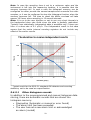
1
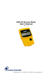
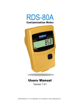
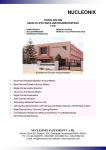
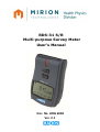
RDS-31 S/R
Multi-purpose Survey Meter
User’s Manual
Doc. No. 2096 6082
Ver. 2.1
NOTE
This document and the information herewith are copyrighted
material as mentioned in the Copyrights Act. No part of this
document may be copied without a written authorization from the
manufacturer.
The manufacturer withholds the right to make changes in the
contents of this document without prior notice.
If you have any comments or suggestions for additions
concerning either the products or this document, please send
them to the address on the back cover. There is a feedback form
at the end of this document.
ATTENTION! The RDS-31 Multi-purpose Survey Meter does not
contain any hazardous or dangerous substances and can be
recycled accordingly. The batteries of the device must be recycled
separately as instructed by the manufacturer of the batteries.
Copyright © Mirion Technologies (RADOS) Oy 2010
Document No.
Version
Issue date
2096 6082
2.1
10.3.2011
Table of Contents
1.
Introduction ............................................................................. 1
1.1
RDS-31 S/R Multi-Purpose Survey Meter ................................................. 1
2
Taking the instrument into use for the first time ...................... 2
2.1 Inserting batteries ......................................................................... 2
2.2 Switch On .................................................................................... 4
2.3 Switch off (OFF) ............................................................................ 4
3
Main parts of the RDS-31.......................................................... 4
3.1 Display of the RDS-31................................................................... 4
3.2 Connectors and strap ............................................................... 5
4
Using the buttons and Special features .................................... 7
4.1 Button pressing times .................................................................... 7
4.2 Normal usage of the buttons........................................................... 8
4.3 Special feature: Shortcut-function ................................................... 8
5
Operation ................................................................................ 9
Switch On ........................................................................................... 9
Switch off (OFF) .................................................................................. 9
5.1 Indication of the measuring unit..................................................... 10
5.2 Display illumination ...................................................................... 10
5.3 Operating the instrument menu ..................................................... 11
5.4 Menu items ................................................................................. 11
5.4.1 Show and reset cumulative dose (DOSE) ............................................... 11
5.4.2
Maximum measured dose rate (MAX.DR)............................................... 12
5.4.3
Chirp Off and setting divider (CHIRP) ...................................................... 13
5.4.4
Show and change dose rate alarm level (DR AL) ................................ 14
5.4.4.1
Fixed dose rate alarm level:......................................................................... 14
5.4.4.2
Sequential dose rate alarm: ......................................................................... 14
5.4.5
Show and change dose alarm level
(DOS.AL)............................. 15
5.4.5.1
Fixed dose alarm level: .................................................................................. 16
5.4.5.2
Sequential dose alarm: .................................................................................. 16
5.4.6
Time to Dose Alarm (TM.2.AL) .................................................................... 17
5.4.7
Diagnostics (DIAG) .......................................................................................... 18
5.4.8
Communication (CONN)................................................................................. 20
5.4.9
Histogram (HISTO) ......................................................................................... 21
5.4.9.1 Other histogram records .............................................................................. 23
5.5 Shortcut functions ........................................................................ 24
5.6 Other displayed messages ............................................................. 27
5.6.1
Low battery warning ........................................................................................... 27
5.6.2
Low battery alarm ............................................................................................ 27
6
6.1
6.2
6.3
6.4
6.5
6.7
6.8
6.9
7
8
8.1
8.2
8.3
8.4
8.5
8.6
8.7
9
9.1
5.6.3
Dose rate alarm (Blinking display) ............................................................ 27
5.6.4
Dose alarm .......................................................................................................... 27
5.6.5
Dose rate Overflow alarm (OFL)................................................................. 27
5.6.6
Error (dEF/Err) ................................................................................................... 28
Configurable Parameters ........................................................ 28
Display illumination ...................................................................... 28
Show and reset cumulative dose (DOSE)......................................... 29
Chirp on/off and chirp rate (CHIRP) ................................................ 29
Show and change dose rate alarm level (DR AL) .............................. 30
Show and change dose alarm level (DOS.AL) ................................... 30
Battery and display test (DIAG) ...................................................... 30
Histogram (HISTO) ....................................................................... 31
Indication unit ............................................................................. 31
Maintenance and Decontamination ......................................... 32
RDS-31 specifications ............................................................. 33
Radiological characteristics ............................................................ 33
Functional Characteristics .............................................................. 34
Electrical characteristics ................................................................ 34
Mechanical characteristics ............................................................. 34
Environmental characteristics ........................................................ 35
Connector ................................................................................... 35
Detector position .......................................................................... 35
Accessories ............................................................................ 36
External probes for RDS-31with Binder connector ............................ 36
1. Introduction
1.1 RDS-31 S/R Multi-Purpose Survey Meter
The new RDS-31S/R Multi-purpose Survey Meter continues the
line of the RADOS survey meters offering modern design and
approach to a wide range of radiation monitoring applications.
RDS-31 is a small hand held, battery-operated survey
instrument utilizing an energy-compensated GM-tube as a
primary detector. It is suited for a wide range of applications in
civil defense, fire fighting, rescue, industrial and laboratory use
due to its versatile functions and rugged construction. With the
accompanying Configuration Software, it is easy to optimize the
behavior of the instrument to meet the various working
conditions and needs. The menu functions, which are available
to the end user, can be selected from the bare essentials (back
light activation only) to functions allowing the alarm limit
setting, dose resetting and histogram functions configurations.
In other words, this meter has its place wherever the user
wishes to observe the ionizing radiation in his/her environment
or work surroundings.
RDS-31 features excellent ergonomics; it is lightweight and
easy to handle with visual and audible alarms and a built-in
vibrating alarm. The instrument can be held and handled firmly
even under difficult conditions thanks to the rubber grip around
the instrument. The large LCD with an Energy Save Backlight
can be easily read both in total darkness and in direct sunlight.
Additionally, to increase the easy operation of the instrument,
the Shortcut-operation can be configured to the Buttons. This
function allows the easy and configurable method of performing
repeated operations such as the Manual Histogram Sample
collection, the Dose value display, the Diagnostics etc. In
addition, to help the users to become accustomed to the
Shortcut-function, a novel Visualization display function can be
configured into the operations. With this aid, it is possible to
adjust the button pressure to the desired length.
1
The basic instrument is easy to take into use, but it also offers
versatile possibilities to measure other types of radiation
qualities by using external probes. The total Mirion range of
external probes from the Turku and Lamanon manufacturing
sites can be attached to the instrument.
These detectors include the GMP-12 series gamma probes, the
GMP-11/GMP-15
alpha/beta/gamma
probes
of
Mirion
Technologies (RADOS) Oy. In addition, the TGS gamma
contamination, Alpha Wound and Alpha 125 alpha contamination
probes from Mirion Technologies (MGP) of France can be
connected to RDS-31. These various detectors can be added to
the instrument using the additional Cable Adapter extending the
capabilities of the instrument. The use of the Cable Adapter also
provides existing customers an easy and cost effective way to
update their current instruments while maintaining the existing
external detectors.
The meter provides an additional protective function to the user:
while using external probes, the meter is still measuring
simultaneously the dose rate using the detector of the
instrument. This allows the alarm to be triggered in case a too
high dose rate or an accumulated dose is measured.
The RDS-31 is ready for use after the batteries (2 x IEC LR6/AA)
have been installed.
2 Taking the instrument into use for the first time
2.1 Inserting batteries
Open the lid of the battery compartment by releasing the fixing
screws with a pozidriv #1 screwdriver and pull the cap out.
2
The instrument uses two IEC (LR6/ HR6) AA-size batteries. The
use of alkaline batteries is recommended, but NiMH batteries
can also be used.
The polarity of the batteries can be seen in the picture below.
It is also engraved in the bottom of the battery compartment.
Insert the batteries and secure the battery cap.
Close the battery cover and tighten the screws first by using a
lower torque and then by increasing the force until the lid
becomes aligned with the bottom. The surface of the lid is
slightly above the instrument bottom surface.
The instrument is now ready for use. If the instrument is not
automatically switched On after replacing the batteries, turn the
instrument On by pressing the push On/Off-button [] until the
instrument starts (about 2s).
Note: The
The use of
instrument
instrument
operation of the instrument is optimized for alkaline batteries.
NiMH batteries is possible. When changing the battery type the
settings must be changed either with the menu function of the
or by using the Configuration Software for RDS-31.
Note: When changing the batteries, also check that there is no dust or dirt
inside the battery compartment. Clean the compartment. Check the
condition of the rubber sealing and the connector cap. Replace the sealing
or the cap in case they have become damaged.
Note: Using excessive force while tightening the screws may damage the
threads of the instrument. Should this happen the case must be replaced.
Note: If the batteries have been totally depleted or the batteries are not
changed within one minute, the Internal Real Time Clock is reset and has to
be set again using theCSW-31 software.
3
2.2 Switch On
Press the [] button until all the segments are displayed and an audible
signal is heard. The meter performs a self-test function:
• All the display segments are lit
• The buzzer is activated
• The display backlight is switched on
• The battery condition is tested
• The HV-generator is tested
• The presence of the RF link is checked and the connection is
established.
• In case the internal Real Time Clock is not set to the proper time,
a ‘CLOCK’ message is displayed
2.3 Switch off (OFF)
To switch the instrument Off:
• Activate the menu (Short [Ξ]).
• The display changes to blinking OFF.
• Press an intermediate []
The display goes blank. The instrument is now switched off.
Note: The instrument does not completely shut down all the internal
circuitry. The RTC-circuit remains active maintaining the time signal. The
energy is supplied with the batteries. This means that the time setting of
the instrument RTC is lost in case the batteries are removed for more than
1 minute.
Note: In case the instrument is to be stored for a prolonged
prolonged period of time,
it is advisable to remove the batteries to prevent any electrolyte leakage to
the battery compartment.
3
Main parts of the RDS-31
This paragraph presents the main parts of the instrument.
3.1 Display of the RDS-31
The display of the RDS-31 is a customized LCD display with the
Energy Saving Backlight (ESB). The ESB-circuitry measures the
ambient light condition and in case the lighting is sufficient, the
backlight is not activated when the buttons are operated.
The display segments
segments are lit when the instrument is started. Also
using the display diagnostics it is possible to check that the LCDmodule is operational.
S1 S2
S3
S4
S5
S6 S7
S8
Units -1
14-S
Units-2
S9
ABG
S10
4
ABGS
Segment Function
Group
Segment Function
Group
S1
The Chirp is activated
S2
All Sounds Muted! ALL!
S3
The Vibration Alarm
Activated
S4
Alarm Condition exists
S5
An External detector is
present
S6
Beta detector
S7
Alpha Detector
S8
RF-link active
S10
Up/Down change; ‘-‘ life
14-S
Main area for measured values and
text messages
Units-1
cps, cpm, dpm, Bq, Bqm
(ΞBq/cm2)
Units-2
µSv, mSv, Sv, µSv/h, mSv/h, Sv/h
µR, mR, R, µR/h, mR/h, R/h (R Ξ rem)
µGy, mGy, Gy, µGy/h, mGy/h, Gy/h
S9
Lit when battery low, Low
battery
ABG
Analog Bar Graph, indication of very
short integration time pulse rate.
Helps in searching.
ABGS
Analog Bar Graph Scale.
Units of the bar graph are
same as the main units.
3.2 Connectors and strap
The connector for an external detector and an external charger
is in the bottom of the instrument. There is also the fixing lug of
the wrist strap. The round connector (Binder 702 series) is used
for external probes, for cable connections and for external
alarming devices.
Wrist strap fixing lug
Charging contacts
Connector and protective cap
RDS-31 Connector
5
Note: Charging connectors are used when the instrument is placed into the
car cradle. In case the RDS-31 uses alkaline batteries, the instrument is not
charged with this connection but it will overdrive the batteries instead thus
eliminating the power consumption of the batteries.
Note: Using the existing external detectors requires the use of a cable
adapter. The adapter transforms the connector of the detector to the
suitable receptacle for RDS-31. In some case the cable adapter is required
also to make the detector electrically compatible with the instrument.
3.3 Push Buttons
There are two push buttons above the instrument display. It
ensures that the user always has the best possible grip on the
instrument even when operating the buttons.
On/Off
Menu
The buttons have bossed and cut features so that they are easy
to distinguish from one another. In addition, the pressure
threshold
of
the
buttons
is
slightly
higher
than
in typical buttons to prevent any unwanted activation of the
button e.g. while wearing gloves.
The two buttons have been named [] and [Ξ]. This indicates
the main purpose of the buttons.
The On/Off button starts and stops (through the menu selection)
the instrument and the Menu button is used to operate the menu
lists of the instrument.
Other functions of these buttons are explained under appropriate
locations.
In this manual the button names or the representing symbol can
be used when describing various operations. The On/Off has the
symbol of [] and the Menu button has the symbol of [Ξ].
6
4 Using the buttons and Special features
Using the buttons is a trivial task. Pushing the buttons requires a
bit more force than, for example, a regular keyboard button
since the surface of the button is above the surface of the
instrument front face. In the RDS-31, the duration of the
pushing of the buttons is crucial with regard to the desired
action, so it is necessary to pay attention to the issue.
4.1 Button pressing times
When operating the instrument, three different length pushes
can be used. There is an audible signal that is given at the start
of each time interval:
• Short (p < 0.75 s)
• Intermediate (0.75 < p < 1.5 s)
• Long ( p > 1.5 s)
Note: With the CSW-31 software the display of the instrument can be
configured so that there is a visual guide to help with timing of button
pressure. This is done using the Analog Bar Graph.
A Short push of the button while
is lit.
An intermediate push while
is lit.
A long push while
is lit.
Note: While the different lengths of pushes add versatility to the operation
of the instrument, it is possible to keep everything simple. Almost all the
features that would need this operation mode can be disabled leaving only
the bare minimum of operations.
The minimum approach is to disable all the menu functions: meter would
be constantly switched On and the On/Off Button would switch the
backlight On for 10 seconds and the Menu button would give the current
accumulated dose in the display for 10 seconds. In the background, the
instrument would perform the diagnostics and record the current status,
dose and dose rate into the histogram memory with each pushing of the
button. Otherwise, the histogram would record the dose and dose rate on
every
preprogrammed
time
interval.
In this mode the instrument could also operate in the Sequential Alarm
mode, which means that when the current Alarm threshold is exceeded and
the alarm triggers On, the pressing of the button would activate the next
Alarm Threshold in the sequence and the instrument would be silenced.
This mode would be most suitable for Fire Fighters and other workers who
need to concentrate on the task at hand rather than the operation of the
meter. When the daily activities are over, the instrument would be
connected to the CSW-31 software where the histogram would be recorded.
7
4.2 Normal usage of the buttons
Normally the Menu button is pressed to activate the user
interface menu and to scroll through the various functions. When
the desired function is in the display, the On/Off button is
pressed to activate the next level of display. Typically this level
shows the currently active configuration of the instrument.
Note: The operation, which is activated by pressing the button can be
changed depending on the context of the instrument. For example, when
changing the alarm levels, the main menu is activated first with the Menu
button. The user scrolls thereafter through the different options with short
presses of the Menu button. When the Dose alarm option is displayed, the
next level of operation is activated with a short pressing of the On/Off
button and the display provides the current active status of the Dose Alarm
Threshold. If this value needs to be changed, the user would not use the
Menu button, but instead use short presses of the On/Off button to scroll
through the list to a point where the new set-point value is displayed. At
this point, an intermediate pressing of the On/Off button activates the new
value. Pressing the button a long time will not have any effect and a short
press would change to the next value in the list.
4.3 Special feature: Shortcut-function
Both buttons can be programmed with two additional operations
when the display of the instrument shows the normal dose rate
values. These operations can be set with the CSW-31 software.
An intermediate or long pressing of the button is used to
activate the Shortcut-function.
For example, the On/Off-button can be programmed so that the
long pressing switches the instrument Off. The default is through
the Menu operation. Alternatively, the Menu-button can be
programmed to perform the Manual Histogram Storage with an
intermediate pressing of the button and a Location change with
a long pressing. With this programming it is easy to pick up the
new measurements from several different rooms/spaces when
performing the Plant surveillance.
8
5
Operation
Switch On
Press the [] button until all the segments are displayed and an audible
signal is heard. The meter performs a self-test function:
• All the display segments are lit
• The buzzer is activated
• The display backlight is switched on
• The battery condition is tested
• The HV-generator is tested
• The presence of the RF link is checked and the connection is
established.
• In case the internal Real Time Clock is not set to the proper time,
a ‘CLOCK’ message is displayed
Switch off (OFF)
To switch the instrument Off:
• Activate the menu (Short [Ξ]).
• The display changes to blinking OFF.
• Press an intermediate []
The display goes blank. The instrument is now switched off.
The instrument has two push buttons. In order to change the
operational parameters of the instrument, the menu must be
activated (see also the menu flow chart). A short beep is audible
when the push button is pressed. See also the page 7 paragraph
Using the buttons and Special features.
In order to activate the menu:
Press the [Ξ] button shortly, the display changes to the first
menu item, e.g. “OFF”. Release the button. Now the menu is
activated for 14 seconds and the menu items can be scrolled by
pressing the [Ξ] button shortly.
In order to activate the menu item:
When the desired menu item is displayed, press the [] button
shortly and the desired menu item is activated.
If the push button is not pressed for 14 seconds after activating
a menu item, the menu and the menu item will be deactivated
automatically and the display returns to the dose rate display.
With the other menu items (other than OFF), pressing the []
button shortly will return the display back to the dose rate.
Note: In some situations the function of the buttons are changed
from the default. The changed functionalities are described later
in the manual.
9
The instrument starts measuring the dose rate and accumulating
the dose immediately when the instrument is switched on.
During the initial start-up, the instrument informs the user that
the time of the Real Time Clock has not been set (CLOCK). This
is performed with the Configuration Software CSW-31.
The parameters of the instrument can be changed using the
menu functions described later in this manual. The Configuration
Software for RDS-31 (CSW-31) is required to change those
parameters that are either disabled from the Instrument Menu
or are included only in the CSW-31. Almost all of the menu
functions can be disabled with the software. When the menu of
the instrument has been activated and the push button is not
pressed for seven seconds, the display returns to the dose rate
display.
5.1 Indication of the measuring unit
The basic instrument RDS-31 has two units available for the
measurements when using the internal GM-detector: Sv-based
and rem-based units (displayed by capital ‘R’ on the display). A
suitable sub-multiplier ‘µ’ or ‘m’ is set to extend the display
range. In addition ‘/h’ is applied to indicate the dose rate. With
external probes, additional units can be
provided in the display, depending on the
external detector.
With external gamma detectors, the same
basic units can be used (Sv/h, Sv, rem/h
and rem). With external pulse mode detectors (GMP-11/15), the
display can be configured to units (cps, cpm, dpm, Bq or Bqm
[representing Bq/cm2 units].
The selected unit is indicated on the right side of the display.
The prevailing dose rate will be displayed within 10 seconds.
5.2 Display illumination
To switch the illumination on, press the [] button once.
The display backlight is lit for 10 seconds
Note: The Backlight state will depend on the configuration and
the ambient light condition.
Note: Pressing the [Ξ] button will activate the backlight, but it
will also activate the Menu
10
5.3 Operating the instrument menu
The actual Menu list is completely dependent on the existing
instrument configuration. This means that in the most basic form
there are no items in the menu list that can be activated with
the button operations even when using the Shortcut-function.
Pressing the button will only illuminate the display and perform
some internal functions.
The following table summarizes the first level of all the possible
menu functions. The user has the total freedom to optimize the
instrument to the specific work by removing those menu
components that are not necessary to
to the work so that the
necessary functions can be reached easier.
5.4 Menu items
Menu
Item
Function
OFF*)
Switching the instrument Off (Immediate
Immediate action with an intermediate
pressing of [] button)
DOSE
Check and reset the current accumulated dose
MAX.DR
Check and reset the current maximum recorded dose rate since last
reset
CHIRP
Adjust the sensitivity of the visual and audible pulse indication
DR AL
Check and change the activated threshold level of dose rate alarm
DOS.AL
Check and change the activated threshold level of dose alarm
TM.2.AL
Display the remaining work time until the next dose alarm is activated
in the current dose rate field
DIAG
Activate the internal diagnostics, check software revision and battery
capacity
CONN
Activate the communication with CSW-31
CSW 31 using the RF-link
RF
HISTO
Operate the Histogram functions and/or
and or pick manually the current data
values into the memory
*)
The Underlined and italic text indicate that action is performed
immediately from this point
5.4.1
Show and reset cumulative dose (DOSE)
The instrument integrates the cumulative dose
continuously into a dose register when switched on.
To see the cumulative dose:
• Activate the menu (Short [Ξ]) and scroll (Short [Ξ]’s) until
• The display changes to DOSE.
11
• Press []shortly and the current measured dose value is
provided
The display shows the cumulative dose.
Note: The same basic unit is used both for the dose and for the
dose rate.
Note: Pressing the [Ξ] button returns to the First menu level
displaying DOSE.
To reset the cumulative dose:
• While the cumulative dose is displayed, press [] shortly
and the display shows the text ‘RESET’ blinking
• Press an intermediate []
The cumulative dose is now set to zero.
The display shows the 0 µSv without any blinking and if no
button actions take place within the time-out period, the display
returns to the dose rate.
Note: Pressing the [Ξ] button
button returns to the First menu level displaying
DOSE.
5.4.2
Maximum measured dose rate
(MAX.DR)
The instrument monitors the maximum dose rate while
measuring. It is possible to check the maximum dose rate value
from the last reset of this field. The value is stored into the
permanent memory so that removing the battery will not clear
the field and its value.
To see the maximum dose rate:
• Activate the menu (Short [Ξ]) and scroll (Short [Ξ]’s) until
• The display changes to MAX.DR.
• Press [] shortly
The display shows the currently recorded Maximum dose
rate in the configured unit.
To reset the maximum dose rate:
• While the current maximum dose rate is displayed, press
[]shortly and the display shows the blinking ‘RESET’ text
• Press an intermediate []
The maximum dose rate is now set to zero.
The display shows the 0.0 µSv/h without blinking and if no
button actions take place within the time-out period, the display
returns to the dose rate.
12
Note: Pressing the [Ξ] button returns to the First menu level displaying
MAX.DR and the configuration can continue
continue from this location onwards.
5.4.3
Chirp Off and setting divider (CHIRP)
The chirp function can be used to activate or deactivate the
audible or visual chirp and to select the Chirp divider. The
possible dividers are: 1/1, 1/2, 1/5, 1/10, 1/20 and 1/50. The
division affects both the audible and the visual chirp function.
Note: The audible and visual Chirp can be disabled individually, but
they share the common dividing ratio when enabled.
To see the chirp state:
• Activate the menu (Short [Ξ]) and scroll (Short [Ξ]’s) until
• The display changes to CHIRP.
• Press []shortly
The display shows CA:OFF| CA/ 1| … |CA/50| depending on
the current state of the Audible Chirp and the common
dividing ratio.
• Press []shortly
The display shows CV:OFF| CV/ 1|…|CV/50| depending on
the current state of the Visual Chirp and the common
dividing ratio.
• Press []shortly
The display shows CH:OFF| CH/ 1|…|CH/50| depending on
the current state of the common dividing ratio.
To change the chirp state:
• While the current chirp state is displayed,
displayed, press []shortly
and the display shows the state of the Audible Chirp
blinking
• Scroll with short [] until the desired value is given
• Press an intermediate []
The Audible Chirp state is now set.
• Scroll with short [] until the desired value for Visual Chirp
is given
The Visual Chirp state is now set.
The display provides the new setting without blinking and if no
button actions take place within the time-out period, the display
returns to the dose rate.
13
Note: Pressing the [Ξ] button returns to the First menu level displaying
CHIRP and the configuration can continue from this location onwards.
5.4.4
Show and change dose rate alarm
level (DR AL)
The dose rate alarm of the instrument can operate in two
different modes:
• Fixed dose rate alarm level
• Sequential dose rate alarm
NOTE: The mode can be selected only by using the CSW-31
software.
5.4.4.1 Fixed dose rate alarm level:
There are 8 different levels for dose rate alarm:
• disabled, 10, 50, 100, 500, 1 000, 5 000, 10 000 or 50 000
µSv/h or mrem/h.
The user may select any one of these to be the active alarm
threshold level.
Note: All these dose rate alarm threshold levels can be changed and stored
into the instrument’s internal memory with the CSW software.
To see the current dose rate alarm threshold level:
• Activate the menu (Short [Ξ]) and scroll (Short [Ξ]’s) until
• The display changes to DR AL
• Press []shortly
The current dose rate alarm threshold value is displayed.
To change the current dose rate alarm level:
• While the current dose rate alarm level is displayed, press
[]shortly and the display starts blinking
• Scroll with []shortly until the desired value is given
• Press an intermediate []
The new alarm limit is activated
Note: Pressing the [Ξ] button returns to the First menu level displaying DR
AL and the configuration can continue from this location forward.
5.4.4.2 Sequential dose rate alarm:
When the sequential dose rate alarm function is enabled, all the
eight dose rate alarm levels will be active in the order of the list
(the default values are the same as in the “fixed dose rate alarm
level”). When the first value on the list is exceeded, the alarm
signal is activated. It can be muted by pressing either one of the
push buttons and the value of the second lowest in the list
14
becomes active. The list will be taken into use in succession until
the last position is set as a reference. To set less than 8 effective
limits, the largest threshold values can be set to include the
same value.
Note: In case the Sequential dose rate alarm is activated and triggered, the
short pressing of either button has no other effect than to acknowledge the
alarm and to mute the audible signal. The display still shows the symbol’
ALARM’ while the condition continues.
Note: When the dose rate becomes lower than the limit on the list, which
has been acknowledged already, exceeding this limit will re-trigger the limit
again.
To enable/disable the Sequential dose rate alarm:
• Activate the menu (Short [Ξ]) and scroll (Short [Ξ]’s) until
• The display changes to DR AL
• Press []shortly
The current state of the dose rate alarm system is
displayed (“lowest dose rate alarm level” = enabled|
DR:OFF =disabled)
To change the state of the Sequential dose rate alarm system:
• While the current state of the dose rate alarm system is
displayed, press []shortly and the display starts blinking
• Select the desired state (lowest level or DR:OFF) with short
[] push, note that only these values are blinking, other
values are shown without blinking indicating that they are
not applicable for this function
• Press an intermediate []
The new state is activated
Note: Pressing the [Ξ] button returns to the First menu level displaying DR
AL and the configuration can continue from this location forward.
Note: The alarming is re-triggerable. This means that when the dose rate
goes below the threshold value and exceeds it again, an audible alarm is
triggered, even when user has earlier muted this level.
5.4.5
Show and change dose alarm level
(DOS.AL)
The dose alarm of the instrument can operate in three different
modes:
• Fixed dose alarm level
• Sequential dose alarm
• Time to Dose alarm
NOTE: The mode can be selected only by using the CSW-31
software.
15
5.4.5.1 Fixed dose alarm level:
There are 8 different levels for dose alarm:
• disabled, 10, 50, 100, 500, 1 000, 5 000, 10 000 or 50 000
µSv or mrem.
The user may select any one of these to be the active alarm
threshold level.
Note: All these dose alarm threshold levels can be changed and stored into
the instrument’s internal memory with the CSW software.
To see the current dose alarm threshold level:
• Activate the menu (Short [Ξ]) and scroll (Short [Ξ]’s) until
• The display changes to DOS.AL
• Press []shortly
The current dose alarm threshold value is displayed.
To change the current dose alarm level:
• While the current dose alarm level is displayed, press
[]shortly and the display starts blinking
• Scroll with short [] until the desired value is given
• Press an intermediate []
The new alarm limit is activated
Note: Pressing the [Ξ] button returns to the First menu level displaying
DOS.AL and the configuration can continue from this location forward.
5.4.5.2 Sequential dose alarm:
NOTE: the sequential dose alarm function can be taken into use
by means of the CSW-31 Software only!
When the sequential dose alarm function is enabled, all the eight
dose alarm levels will be activated in the order of the magnitude
(the default values are the same as in the “single dose alarm
level”). When the first value on the list is exceeded, the alarm
signal is activated. It can be muted by pressing either one of the
push buttons and the second lowest value in the list becomes
active. The list will be taken into use in succession until the last
position is set as a reference. To set less than 8 effective limits,
the largest threshold values can set to include the same value.
Note: In case the Sequential dose alarm is activated and triggered, the
short pressing of either button has no other effect than to acknowledge the
alarm and to mute the audible signal. The display still shows the symbol
“AL” (=ALARM) and the triggered level while the condition continues.
To check the status of the sequential dose alarm:
16
Activate the menu (Short [Ξ]) and scroll (Short [Ξ]’s) until
The display changes to DOS.AL
Press []shortly
The current state of the dose alarm system is displayed
(“lowest dose alarm level” | D :OFF = disabled)
To enable/disable the Sequential dose alarm:
• Activate the menu (Short [Ξ]) and scroll (Short [Ξ]’s) until
• The display changes to DOS.AL
• Press []shortly
The current state of the dose alarm system is displayed
(“lowest dose alarm level” = enabled| D :OFF =disabled)
To change the state of the Sequential dose alarm system:
• While the current state of the dose alarm system is
displayed, press []shortly and the display starts blinking
• Select the desired state (lowest level or D :OFF) with short
[] push, note that only these values are blinking, other
values are shown without blinking indicating that they are
not applicable for this function
• Press an intermediate []
The new state is activated
•
•
•
Note: Pressing the [Ξ] button returns to the First menu level displaying
DOS.AL and the configuration can continue from this location forward.
Note: The alarm condition can be reset only by resetting the dose register.
5.4.6
Time to Dose Alarm (TM.2.AL)
NOTE: the Time to Dose alarm function can be taken into use by
means of the CSW-31 Software only!
The Time to Dose alarm function can be enabled to show the
estimate of the remaining work time until the next dose alarm is
activated in the current dose rate field.
In the Fixed dose alarm mode, the procedure how to show and
change the valid dose alarm level is described above and will set
a new reference point for this calculation.
In the sequential dose alarm mode the reference value can
change when the user acknowledges the alarm and the
instrument changes the alarm threshold to the next limit in the
list.
To check the status of the Time to Dose Alarm:
• Activate the menu (Short [Ξ]) and scroll (Short [Ξ]’s) until
• The display changes to TM.2.AL
17
• Press []shortly
The current status (“the alarm limit value used for Time to
Dose display” or “disabled= DISAB”) is displayed
5.4.7
Diagnostics (DIAG)
The Diagnostics function of the RDS-31 is used to manually
activate the internal checking functions of the high voltage,
the operating voltage and the battery capacity. During this
process the user may also check the operation of all the
display segments, the visual alarm LED, the audible alarm and
the vibration alarm. The instrument software revision, XX and
XXX can also be seen. The Diagnostics sub-functions are
provided in the following table
Function | Description
Display
8.8.8.8.8
*)
Main test functions can be activated under this
All segments are lit
- The Buzzer is activated
- The Vibration motor is activated
- The RED alarming LED is activated
The measured performance parameters are stored into the
Histogram memory for later diagnostics
GRAPH
V. 1.00
Reserved for further use
CL.CHK
Start the calibration check procedure
Chooses the target dose rate that is used. After a fixed 1
minute waiting time the instrument measures a dose of 100
µSv (time calculated from the rate). In case the measured
dose is within 10% from expected dose OK, otherwise warn.
B:74
Battery Capacity (here 74 % of the full value)
Current revision of the firmware (Major. Minor)
LOADR
Activate Firmware loading / Reset instrument
*)
Underlined and italic cursive is in use when the display is blinking thus
indicating an immediate action followed with an intermediate pressing of
the [] button.
To activate the diagnostics functions:
• Activate the menu (Short [Ξ]) and scroll (Short [Ξ]’s) until
• The display changes to DIAG
• Press []shortly
The display shows blinking “8.8.8.8.8”
To perform the diagnostics:
18
• While the “8.8.8.8.8” is blinking
• Activate diagnostics with an intermediate []
o All segments are lit
o The buzzer is activated
o The vibration motor is activated
o The RED alarming LED is activated
The display indicates the capacity of the battery B:xx (%)
To check the firmware major and minor revision or to activate
the new firmware downloading:
• While the “8.8.8.8.8” is blinking
• Press []shortly
The display provides the Major Firmware revision
• While the Major Firmware revision is displayed
• Press []shortly
The display provides the CL.CHK
o While the CL.CHK is displayed
o Press []shortly
o A dose rate value is provided. This value is set to 1
mSv/h as a default. With the CSW-31 Pro, the value
can be set to a more optimal value between 300
µSv/h … 3 mSv/h
The display now provides WT:ss, where the seconds are
counted down from 59 to 00 at which point the calibration
check is started.
o After the pre-calculated time, the measured dose is
provided and the results are stored into the
Diagnostics histogram.
o In case of falling outside the ± (15+X) µSv limits,
where the X is the estimated uncertainty of the
calibration check dose rate, it is advised to perform
the recalibration of the instrument.
• While the CL.CHK is displayed
• Press []shortly
• The display provides a Blinking “LOADR”
• Activate the download with an intermediate []
The Display provides stable LOADR
Note: If the communication line is not activated within the time-out period,
the instrument is reset and normal operation is resumed.
Note: The result of the calibration check depends on the irradiation source
energy. The instrument is originally calibrated with Cs-137 and in case a
different type of radiation source is used, the result should be compared to
the energy dependency of the instrument.
19
5.4.8
Communication (CONN)
There are two main communication link selections
possible in the RDS-31 instrument. The first method is the RFlink and the second is the Cable-link method. Both connections
are established with a suitable adapter connected to the USBport of the PC. The adapter will create a HID-class device using
propriety Vendor- and Product codes to the Operating System
register. When the CSW-31 software is active, there is a driver
software, which will monitor the connected devices in the
system. When the RDS-31 communication adapter device is
connected to the PC, the link from the CSW-31 to the adapter is
activated and remains waiting the RDS-31 instrument to be
connected to the adapter.
When the Cable-adapter to the PC –link is established and the
instrument is connected
connected to the adapter, the communication
between the instrument and the CSW-31 is activated
automatically.
When the RF-adapter to PC –link is established, the instrument
is manually set to start the communication. This activation is
performed through the menu operation as described below.
Note: When a large amount of data requires to be downloaded from the
instrument to the system (e.g. the Histogram) it is advisable to use the
cable link due to the higher communication speeds in use.
Note: When the firmware of the instrument is to be updated with a new
release, the cable adapter is suggested for reliability.
To activate the RF-communication:
• Activate the menu (Short [Ξ]) and scroll (Short [Ξ]’s) until
• The display changes to CONN
• Press []shortly
The current state of the communication link is displayed
(CON:ON | CON:OF)
To change the state of the communication link:
• While the state of the communication link is displayed,
press []shortly and the display starts blinking
• Scroll with short [] until the desired state is given
• Press an intermediate []
The new state is activated
Note: If the original state is CON:OF, the instrument attempts to establish
a communication link with the RF-adapter. If the counterpart is not found
within approx. 7 seconds, the instrument returns to the CON:OF state and
continues the normal dose rate measurement.
20
Note: If the original state is CON:ON and there is an active link established
with the RF-adapter and the CSW-31 software, this link is disconnected and
the instrument returns to the CON:OF state and continues the normal dose
rate measurements. Disconnecting the RF-link in the middle of the
configuration procedure between the instrument and the CSW can lead to
an unknown configuration state of the instrument.
Note: The RDS-31 may continue the normal measurements while
communicating. In case the RF-link is used for the communication, the
external probes can be connected to the instrument. In case a cable-link is
used, the measurements are carried out only with the internal detector.
Note: Pressing the [Ξ] button returns to the First menu level displaying
CONN and the configuration may continue from this location onwards.
5.4.9
Histogram (HISTO)
The Histogram functions of the RDS-31 are very
versatile when compared to the RDS-30. The menu functions of
the Histogram are summarized in the following table.
First level
HISTO
Second
level
STATE
LOC.
INT
MAN
Third
Level
Show the
current
state of the
timed
histogram
(ON | OFF)
Show the
current
location
information
Show the
current
Sample Time
in use
Picks
current
values into
the
histogram
memory
Fourth
Level
Change the
state from
the list
Change the
location from
the list
Choose new
Sample
interval from
the list
CLEAR
The histogram function of the user interface has the following
main features:
STATE:
• The STATE provides the currently active status of the timed
histogram logging. When ON
ON the measurement data is
stored into the histogram memory using the determined
interval.
• The user can set the automatic
automatic logging ON or OFF from this
menu
• It is possible that the STATE is set to OFF, but in case of an
alarm of the dose rate, the histogram data is automatically
stored while the condition exists.
LOC.:
21
• The location of choice is stored as additional information to
the logged dataset. It can be used with room control
measurements
or
with
specifically
fixed
address
measurements. With the CSW, it is possible to filter the
datasets using a specific location thus having the possibility
to follow trends in the dose rates.
• It is possible to specify a mnemonic for the 16 locations to
ease the use.
• It is possible to fix longitude and latitude values to the 16
first locations thus allowing the placement on map
applications.
• There are up to 255 numbered locations. The location 0 is a
general purpose placement.
INT:
• This is the sample time interval in use with the automatic
logging of data.
• The possible selection for the time is: 10s, 20s, …
MAN:
• It is also possible to store manual samples into the
histogram memory. In this case, only the immediate value
in the display is stored. With timed logging, the average
and maximum dose rate values are also stored.
CLEAR:
• Clears the histogram
Note: When an external detector is connected to the instrument, the
histogram is storing the data from the internal detector and from the
external detector.
The memory is able to store approximately 30000 data sets with
all the measured information (immediate value in the display,
the average and maximum dose rate from the previous storing,
the location, time). The final number of stored data sets
depends on the amount of diagnostics information that is also
stored into the same memory area.
The histogram memory is downloaded into the CSW-31 software
through the communication link. When using the RF-link, it must
be noted that the download times can be quite long in case the
memory is filled with data.
22
Note: In case the sampling time is set to a minimum value and the
instrument is left into the measuring location, it is possible that the
memory becomes full. In such a case the histogram memory can be
configured to either provide the newest samples and overwrite the older
samples, or it can be configured to stop the histogram function when the
memory becomes full. The time to reach the buffer overload will take
approx. 80 hours when sampling in 10 second intervals.
Note: It is up to the user whether or not to use very short intervals in
the background dose rate fields since the data is partially redundant.
Typically new statistically independent data is available only 5 times per
hour in a dose rate of 0.1 µSv/h. The Independent result in this case
means that the entire internal counting registers do not include any
effect of the earlier results.
The duration to receive independent results
1000
100
Time [s]
Time
Indep.
Res/h
10
1
0,01
0,1
1
10
100
Dose Rate [µSv/h]
*)
Typical result for the RDS-31 standard GM-detector and counting
statistics, not to be used as a specification.
5.4.9.1
Other histogram records
In addition to the preprogrammed and manual histogram data
storing, there are automatic records that are stored into
histogram memory:
• Diagnostics (Automatic or manual or error found)
• The alarm limit has been exceeded
• The user has set a new alarm limit or acknowledged
an alarm (muted)
23
• The user has reset the dose or the max dose rate
• The instrument has been calibrated (New and old
Coefficients are stored)
Normal histogram memory: The internal structure of the
histogram memory is designed in such a way that the Daily
basis functions are stored inside a circular buffer, where a
header separates the data sets. This part has a maximum limit
of storing approx. 30000 normal data sets. Other daily
activities are stored within this buffer area as well, such as the
instrument Switch On/Off, the Dose Reset, the Max.Dose rate
Reset, the Alarm limit change, etc. The more activities are
stored, the more the data records consume the Dose Rate
histogram memory.
Calibration memory: The results of the 64 newest
calibrations are stored in the memory. The oldest are
overwritten in case more than 64 calibrations are performed.
Diagnostics memory: The first start-up of the day is stored
here. In case the instrument operates continuously without
going to the OFF state, an automatic diagnostics is run at
00:00:00 and the results are stored into a specific diagnostics
memory. This memory is able to store the data of over one
year of operation. When the memory becomes full, the oldest
diagnostics data is overwritten.
These special memory areas cannot be cleared with the
CSW-31 LITE/PRO software and require a service
5.5 Shortcut functions
The RDS-31 offers the Shortcut function to the user to ease
the daily activities. These functions can be configured with the
CSW-31 software. With the free version (LITE) of the CSW-31
software, the menu functions in the 2nd table below can be
configured to the RDS-31 instrument. With the CSW-31 PRO,
there are additional features that can be configured into the
instrument Shortcuts.
With CSW-31 LITE there can be one ShortCut to the menu
button ([Ξ]) only. With the CSW-31 PRO, the user can
configure two shortcuts to both buttons ([] and [Ξ]).
Note: To avoid confusion and misuse of instrument, the user should
check with the CSW-31 software the programming of the ShortCut.
CSW-31 LITE
24
ShortCut
Function
ShortCut-1
Not In Use
ShortCut-2
Not In Use
ShortCut-3
Not In Use
ShortCut-4
Long press of
[Ξ ]
Time
Pressing more than
2s
With CSW-31 LITE there can be one ShortCut to menu
button [Ξ]. In addition, the selection of choices is limited.
With the CSW-31 PRO, the user can configure two short
cuts to both buttons ([] and [Ξ]) allowing up to 4
different choices.
CSW-31 LITE
ShortCut
Function
Operation
ShortCut-4
(Long press of
[Ξ ] )
Chirp set
When activating
the shortcut, the
display of the
instrument goes
into the menu
item Chirp. The
normal button
operations are
allowed from this
point onwards.
Maximum dose
rate
When activating
the shortcut, the
display goes
directly to
displaying the
maximum dose
rate from the
last reset of the
field.
Diagnostics
The menu item
DIAG is
activated. The
normal button
operations are
allowed from this
point forward.
Note: In case the instrument configuration would not allow the
function that is programmed into the ShortCut, the ShortCut
function overdrives the instrument configuration. This means that
even in a case where the instrument menu is completely disabled,
some limited actions can still be performed using the ShortCut
function.
25
CSW-31 PRO ShortCuts
ShortCut
Function
Time
ShortCut-1
An intermediate
pressing of []
Pressing more
than 1s, but less
than 2s
ShortCut-2
A Long pressing of
[]
Pressing more
than 2s
ShortCut-3
An intermediate
pressing of [Ξ]
Pressing more
than 1s, but less
than 2s
ShortCut-4
A Long pressing of [Ξ]
Pressing more
than 2s
CSW-31 PRO: Possible ShortCut actions and specific information
Function
OFF
*)
Note
With the Shortcut, it is possible to switch the
instrument off directly, without the need to first
activate the menu.
DOSE
The menu item of DOSE
DOSE –
Accumulated
dose
This is the accumulated dose value.
MAX.DR
The menu item of MAX.DR
MAX.DR –
Measured
max.rate
The measured maximum dose rate.
CHIRP
The menu item of CHIRP
CHIRP –
Dividing value
The currently activated dividing of the pulse
indicator.
DR AL
The menu item of DR AL
DR AL – Active
value
Currently active alarm value (Fixed limit system in
use)
The Dose reset is not an allowed ShortCut item
The maximum dose rate reset is not an allowed
ShortCut item
Disable/Enable (Sequential alarm limit system in
use)
DOS.AL
The menu item of DOS.AL
DOS.AL – Active
value
Currently active alarm value (Fixed limit system in
use)
Disable/Enable (Sequential alarm limit system in
use)
TM.2.AL
The menu item of TM.2.AL
TM.2.AL –
Remaining time
The measured remaining time to Dose alarm
activation. Based on the measured dose rate.
DIAG
The menu item of DIAG
DIAG - Battery
Show the battery capacity
CONN
The menu item of CONN
HISTO
The menu item of HISTO
HISTO –
Location
The currently selected location is displayed
HISTO – Manual
Manual sample of dose rate is placed into histogram;
26
Sample
The Location is the same as with the current
configuration. After 1.5 sec. the display returns to
the primary dose rate display.
5.6 Other displayed messages
Low battery warning
5.6.1
An audible low battery warning signal combined with a blinking
battery symbol indication repeated every 6 minutes when the
battery capacity is 10% < Capacity < 30%
Low battery warning: _______ _ _______ (Long – Short – Long
Bleep in five minutes intervals). The dose rate measurement
continues normally.
5.6.2
Low battery alarm
The display shows "LOBAT" blinking and the audible alarm is
activated when the battery capacity is <10%.
Low battery alarm: _______ _ _______ (Long – Short – Long Bleep
in 20 seconds).
NOTE: The dose rate measurement is prevented.
5.6.3
Dose rate alarm (Blinking display)
The dose rate display is blinking and the continuous audible
alarm is on. The audible alarm can be reset by pressing the push
button.
Dose rate alarm: ------ (two beeps per second).
5.6.4
Dose alarm
The dose rate display is on and the current dose alarm level
alternates in the display and the continuous audible alarm is on.
The audible alarm can be reset by pressing the push button.
Dose alarm: - - - - - - (one beep per two seconds).
5.6.5
Dose rate Overflow alarm (OFL)
When the measurement limits are exceeded, the display shows
“OFL” (blinking). The continuous audible alarm is on.
____
Dose rate overflow: ____
(continuous beeps).
The overflow alarm cannot be reset.
Note: When the dose rate overflow has been activated, there will
be a message from this event in the dose read-out. When the
dose is given, the display alternates between “DR.OFL” <->
dose. This flag will be set when the dose is reset. This is to
27
inform the user that the measured dose might not give the true
value due to exceeding the maximum measurable dose rate.
5.6.6
Error (dEF/Err)
In case there is a critical internal failure in the instrument, the
Defect error is activated. The continuous audible alarm is on.
_
_______
Error alarm: _______
(continuous bleeps every two
seconds).
The dose rate measurement is prevented.
Error codes and types:
Error1 = CAL.DF Calibration error, the calibration coefficient is
default, or is out of accepted limits.
Error2 = FLS.DF Non-volatile memory error
Error3 = DET.DF Detector is faulty (internal or external)
Error4 = DG1.DF High voltage is not within specified range
Error5 = DG2.DF Internal power supply is out of specified range
Error6 = DG3.DF Firmware CRC error; the bit sum check of
embedded software failed
Error7 = LFE.DF Cumulative dose overflow (>10 Sv). The GMdetector can be end of life.
Should an error occur, write down the Error message and return
the meter to the manufacturer (contact info: see the last page of
this manual) for service. The internal diagnostics memory will
also store critical errors, but in case the problem is the memory
itself, it cannot be completed.
6
Configurable Parameters
All of the menu items can be disabled from the menu with the
CSW software. When a menu item is disabled, it is not visible
in the menu list.
6.1 Display illumination
The RDS-31 has an Energy Save Backlight feature. This means
that in case the amount of ambient light is sufficient, the
backlight will not be activated regardless of the configuration.
Pressing any button or length will activate the backlight. To
only achieve the backlight activation, press the []-button
shortly.
Option
Effect
Configuration 1:
When the push button is pressed, the display
28
backlight is lit for 10 seconds (timeout mode).
Configuration 2:
The display backlight is switched on by
pressing the push button and remains lit until
the button is pressed again (user-defined
mode).
Configuration 3:
The backlight is on permanently (constantly
on –mode).
Configuration 4:
The backlight is off permanently (constantly
off –mode).
Note: There is no method in the instrument menu to change the
configuration.
6.2 Show and reset cumulative dose (DOSE)
The cumulative dose is always measured from the
internal tube, even when using an external detector. The
dose alarm can therefore be used to warn the user even
when using any type of an external detector. The dose is
accumulated always when the instrument is switched On.
Option
Effect
Configuration 1:
The Cumulative Dose is not displayed in the
menu.
Configuration 2:
The Cumulative Dose can be checked and
reset using the push button of the instrument.
Configuration 3:
The Cumulative Dose can be checked, but not
reset through the menu of the instrument.
6.3 Chirp on/off and chirp rate (CHIRP)
The RDS-31 instrument has both an audible and a visual
pulse indicator, Chirp. These can be individually disabled,
but they share the same dividing value when activated.
Option
Effect
Configuration 1:
The chirp configuration is not possible through the
menu
Configuration 2:
The Audible chirp is disabled (Visual chirp is
*)
X)
The Audible chirp is enabled (Visual chirp is
*)
The Visual chirp is disabled (Audible chirp is
*)
Configuration 5:
The Visual chirp is enabled (Audible chirp is
*)
Configuration 6:
The pulse rate from the detector is divided by a
value from the fixed list:
1/1, 1/2, 1/5, 1/10, 1/20 and 1/50
Configuration 3:
Configuration 4:
*)
The state X is either Enable or Disable
29
X)
X)
X)
6.4 Show and change dose rate alarm level (DR AL)
The Dose rate alarm is always measured from the internal
tube even when an external detector has been inserted.
This is to ensure the protection of the user of any telepole
device.
This is a configurable function with 3 options:
Option
Effect
Configuration 1:
Disabled
Configuration 2:
The current alarm level can be displayed but
cannot be changed using the instrument’s push
button.
Configuration 3:
The Alarm Level is displayed and can be changed
using the push button.
6.5 Show and change dose alarm level (DOS.AL)
The Dose alarm is always measured from the internal
tube even when an external detector has been inserted.
This is to ensure the protection of the user of any telepole
device.
This is a configurable function with 3 options:
Option
Effect
Configuration 1:
Disabled
Configuration 2:
The current alarm level can be displayed but
cannot be changed using the instrument’s push
button.
Configuration 3:
The alarm Level is displayed and can be changed
using the push button.
6.6 Time to Dose Alarm (TM.2.AL)
The Time to Dose alarm provides the remaining time for
the user until the next active dose alarm is exceeded in
the current dose rate field. Due to a high variance in the
dose rate this value will have a large variance. The
maximum value is 99:59.
Option
Effect
Configuration 1:
Disabled
Configuration 2:
Enabled
6.7 Battery and display test (DIAG)
The diagnostics function is performed every 10 minutes
while the instrument is set ON. The diagnostics results
are stored into the histogram memory:
• When the instrument is switched ON
30
• In case of an error in the diagnostics
• Once per day
The diagnosed properties are: the Battery capacity, the
high voltage, the internal operating voltage, the battery
voltage and the temperature.
This is a configurable function with 3 options:
Option
Effect
Configuration 1:
Disabled from the menu
Configuration 2:
Manual diagnostics is allowed.
Configuration 3:
The diagnostics result is stored into the
Histogram memory only in case of an error (when
set)
6.8 Histogram (HISTO)
The histogram function stores the dose and dose rate
information into the memory for later analysis. The
storing of the data can be manually activated or time
sampled. Each data set consists of all the measurable
data available and, the user can activate what data is to
be processed through the filtering options during the
read-out.
This is a configurable function with 3 options:
Option
Effect
Configuration 1:
Disabled from the menu
Configuration 2:
Manual storing is allowed.
Configuration 3:
Several selectable function can be enabled:
• Clear Buffer
• Change State (ON/OFF)
• Histogram rolling enabled (optional)
• Histogram from external detector
(optional)
• Auto histogram from Alarm
The selected data is stored automatically into
the Histogram memory (when set)
6.9 Indication unit
The displayed units can be chosen between Sv and rem.
The rem unit is shown in the display as more generic ‘R’.
This is a configurable function with 2 options:
Option
Effect
Configuration 1:
µSv/h
Configuration 2:
mrem/h
31
7 Maintenance and Decontamination
No specific maintenance is required except for a periodic check
of the calibration. The authorities or the Health physicists
typically determine the checking interval. Once a year under
demanding conditions or every second year under typical
laboratory conditions is a recommended interval in maintaining
the proper operational reliability of the instrument.
Cleaning and decontamination may be carried out by using
decontamination solutions suitable for use with ABS polymer and
PMMA materials.
The replacement of the batteries:
Open the battery compartment cover with a suitable
screwdriver (Pozidrive #1). Remove the old batteries and
replace with new ones. Note the correct polarity. The use
of AA alkaline batteries (IEC LR6) is recommended but
NiMH rechargeable batteries can be used under normal
conditions. Note that rechargeable batteries should not be
charged below 5 °C temperatures. The capacity at these
temperatures can be lower than anticipated.
Close the cover firmly especially in case the instrument is
used in humid conditions.
Note! After fitting fresh batteries, it is recommended to perform the
functional test (DIAG). If the low battery sign “LOBAT” appears in
the display after the test, refit the batteries.
Note: When changing the battery type between alkaline and
rechargeable, use the CSW-31 software to indicate the
change to the instrument. Otherwise the battery capacity
counter and charging functions can be set in false settings.
When changing batteries the instrument assumes that
alkaline batteries have been inserted and the charging
functions are disabled.
32
8 RDS-31 specifications
Order catalog # 1233-268:
RDS-31 S (Sievert model)
Both battery cover models
Batteries (2 x AA/LR6 size)
Carrying strap
User’s Manual
USB-RF LINK-31
CSW31 Lite Configuration Software
Order catalog # 1233-260:
RDS-31 S
Both battery cover models
Order catalog #1233-261
RDS-31 R
Both battery cover models
8.1 Radiological characteristics
• radiation detected: gamma and X-rays, 48keV...3
MeV; Alpha and Beta radiation with external probes
• ambient dose equivalent H*(10)
• dose rate measurement range: 0.01 µSv/h...0.1
Sv/h
(1 µrem/h...10 rem/h)
• dose measurement range: 0.01 µSv...10 Sv
(1 µrem...1000 rem)
• resolution: three significant digits or 0.01 µSv/h on
dose rate and 0.01 µSv on dose (1 µrem/h on dose
rate and 1 µrem on dose)
• calibration accuracy*: ± 5%, 137Cs, calibration
direction and in the calibration field, temperature
+20 °C (68°F)
• dose rate linearity: ± 15% ± least significant
number 0.05 µSv/h...0.1 Sv/h (5 µrem/h to 10
rem/h)
33
• variation of the response due to photon radiation
energy and angle of incidence: (R E,A) 71% < RE,A <
160% (48 keV...3 MeV), ± 60°
*compared to Finnish National Laboratory STUK
8.2 Functional Characteristics
• two buttons to operate the instrument
• configurable units: Sv(/h), R(/h), with external
detectors Gy(/h), cps, cpm, dpm and Bq
• versatile histogram functions ( dose rate, dose,
diagnostic logging depending on configuration, time
stamp, optional location control for mapping and
repeating room control analysis)
• additional histogram analyzing capabilities on CSW31 Pro software; XML-format file storage
• real time clock function
• configurable audible, visual and a vibration alarm
• RF-communication and USB-communication with
suitable adapter
• customized LCD display with 5 digit 14-segment
floating point area and special symbols for alarm,
external probe, battery, RF communication, vibration
alarm, chirp and mute
8.3 Electrical characteristics
• power supply: 2 x AA (R6) size batteries (alkaline or
NiMH)
• contacts for external power and charging of NiMH
battery (charging conditions +5... +35°C)
• operation time with fresh batteries more than 4
months at background radiation at +23°C, 8 h
use/24h.
• operation time with fully charged NiMH batteries
more than 1 month at background radiation at
+23°C, 8 h use/24h. At higher temperatures the
operation will be shorter
• battery life ca. 1000 h (when only standard features
are in use)
8.4 Mechanical characteristics
• case high impact durable plastics reinforced with
glass fibre
• ergonomic design, rubber grip and cushion around
the case
34
• enclosure class IP67 (IEC 60529), water proof
including battery compartment
• dimensions: 100 mm x 67 mm x 33 mm (3.93 in x
2.63 in x 1.29 in)
• weight: 175 g without batteries (0.385 lb), 220 g
with batteries (0.485 lb)
• wrist/neck strap
• belt clip
8.5 Environmental characteristics
• operating temperature -25 °C...+60 °C (-13 °F to
131 °F)
• storage temperature -40 °C...+70 °C (-40 °F to 158
°F)
• relative humidity: up to 85% at +35 °C (95 °F)
• fulfills the RF-immunity levels of applicable
standards
8.6 Connector
• Binder-702-series
• existing detectors (used with RDS-110/RDS-200)
with special adapter
• external alarm output max. 24V
8.7 Detector position
The location of the GM-detector central point is marked
on the surface of the case in the pictures below.
35
9 Accessories
USB-RF Link-31 LITE + CSW-31 Configuration Software
Order number:
1233-262
USB-RF Link-31 PRO + CSW-31 Configuration Software
Order number:
1233-263
USB-Cable Link-31 LITE + CSW-31 Configuration Software
Order number:
1233-264
USB-Cable Link-31 PRO + CSW-31 Configuration Software
Order number:
1233-265
The Configuration Software (CSW) is used to check the status of
the instrument, to change its operational parameters and to setup the histogram operation (for details see the CSW
Configuration Software for RDS-31 User’s Manual)
RDS-31 cable adapter for external Multirad LLR probes
Order number:
1233-266
RDS-31 cable adapter for external GMP series probes
Order number:
1233-267
9.1 External probes for RDS-31with Binder connector
GMP-11-3 Beta Probe for RDS-31
Order number:
1233-274
Range: 0 to 10 000 cps
GMP-15-3 Pancake Beta probe for RDS-31
Order Number:
1233-275
Range: 0 to 10 000 cps
36
GMP-12-3 Gamma probe for RDS-31
Order Number:
1233-276
Range: 0.05 uSv/h to 10 Sv/h
GMP-12L-3 Gamma probe for RDS-31
Order Number:
1233-277
Range: 0.05 uSv/h to 100 mSv/h
GMP-12H-3 Gamma probe for RDS-31
Order Number:
1233-278
Range: 100 uSv/h to 10 Sv/h
As standards, specifications and
design are subject to change
over a period of time,
please request for the confirmation of the
information given in this publication.
Lamanon – France
Tel +33 (0)4 90 59 59 59
Smyrna (GA) – USA
Tel +1 (770) 432 2744
Turku – Finland
Tel +358 (0)2 4684 600
Other countries
Tel +33 (0)4 90 59 60 41
Hamburg – Germany
Tel +49 (0)40 85193-0
RADOS Doc.No
v. 2.1
37
2096 6082
FEEDBACK FORM
We are continuously working hard at producing correct and easy-to-read technical
documents. However, complex systems are often difficult to explain or understand
and therefore mistakes or inadequacies may occur occasionally in the
documentation process. To correct these errors we would like to hear your opinion
on this document.
If you have noted mistakes, or if there are parts that are unclear, please let us know. Make a copy of this page,
describe the problem and send the copy to us here in RADOS.
To:
Mirion Technologies (RADOS) Oy/ Technical Documents
P.O. Box 506, FIN-20101 Turku, Finland
Fax: +358-2-468 4601
This way you will help us in supplying you with even better documents. The best feedback will be rewarded.
Notes on this document
Name of the document:
-------------------------------------------------- Issue date: ----------------------------------
----------------------------------------------------------------------------------------Description of the mistake or problem:
Page no.
Correction:
-------------------------------------------------------------------------------------------------------------------------------------------------------------------------------------------------------------------------------------------------------------------------------------------------------------------------------------------------------------
-----------------------------------------------------------------------------------------------------------------------------------------------------------------------------
Notes on the product
Name of the product:
-----------------------------------------------------------
Version: ---------------------------------------
Description of the mistake or problem:
Correction:
-------------------------------------------------------------------------------------------------------------------------------------------------------------------------------------------------------------------------------------------------------------------------------------------------------------------------------------------------------------------------------------------
-----------------------------------------------------------------------------------------------------------------------------------------------------------------------------------------------------------------
General Notes
----------------------------------------------------------------------------------------------------------------------------------------------------------------------------------------------------------------------------------------------------------------------------------------------------------------------------------------------------------------------------------------------------------------------------------------------------------------------------------------------------------------------------------------------------------------------------------------------------------------------------------------------------------------------------------------------------
If you need more room, please use attached pages.
Name:
Company:
Address:
Position:
Telephone:
Fax:
38
39
40