1
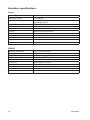
Connections
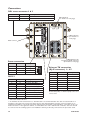
DSL screw connector 1 & 2
Position
1
2
Direction
In/Out
In/Out
Description
2-wire Receive/ Transmit SHDSL
2-wire Receive/ Transmit SHDSL
LED indicators
(for details see next page)
LED indicators
(for details see
next page)
Earth connect
LED indicators, also
integrated in RJ-45 connector.
(for details see next page)
Power connection
Position
Direction*
1
In
Description
+ Voltage A
2
3
4
In
In
In
+ Voltage B
Common
Common
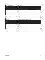
RS-232
Position
1
2
3
4
5
6
7
8
9
Direction*
In
Out
Out
In
Out
In
-
Description
Not connected (DCD)
Received data (RD)
Transmitted data (TD)
Data terminal ready (DTR)
Signal ground (SG)
Data Set Ready (DSR)
Request To Send (RTS)
Clear To Send (CTS)
Not connected (RI)
Ethernet TX connection
(RJ-45 connector) 1 – 4**
Position
1
2
3
4
5
6
7
8
Direction*
In/Out
In/Out
In/Out
–
–
In/Out
–
–
Description
TD+
TD–
RD+
Not Connected
Not Connected
RD–
Not Connected
Not Connected
CAT 5 cable is recommended.
Unshielded (UTP) or shielded (STP) connectors
can be used.
* Direction relative this unit
** To minimise the risk of interference, a shielded cable is recommended when the cable is located inside 3 m
boundary to the rails and connected to this port. The cable shield should be properly connected (360°) to an
earthing point within 1 m from this port. This earthing point should have a low impedance connection to the conductive enclosure of the apparatus cabinet, or similar, where the unit is built-in. This conductive enclosure should
be connected to the earthing system of an installation and may be directly connected to the protective earth.
14
6642-22203