1
b)
Extrusion and two-sided casting
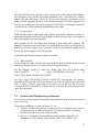
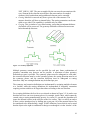
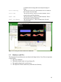
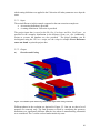
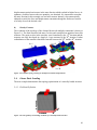
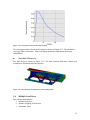
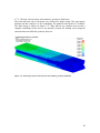
Different phases in the evolution are depicted in Figure 5-5. One can see that a lot of
material was removed early. The final geometry evolved by considering the geometry
definitions was significantly different than the case when no manufacturing constraints
were considered. The I-section evolved makes intuitively sense.
Figure 5-6: Evolution of the beam using extrusion and two-sided casting constraints.
5.3.
Force-Displacement Constraints
The next example demonstrates a simulation with multiple constraints.
5.3.1. Problem Definition
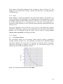
Fixed
H=200mm
W=200mm
Fixed
L=800mm
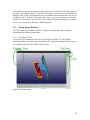
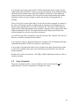
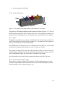
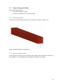
Figure 5-7: The geometry and loading conditions of the multiple constraints example.
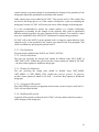
The geometry and loading conditions for the example are shown in Figure 5-7. This is a
fixed-fixed beam with a central load. The design part was meshed with 10mm3 elements.
5.3.2. Input
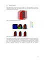
The center load was assigned at the location of the pole hitting the beam. The desired
mass fraction for this example was 0.25. A maximum of 100 iterations were allowed. The
47