1
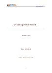
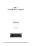
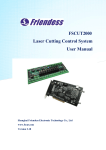
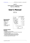
PMC2 PMC2 User Manual Version: 20150519 PMC2 Table of Content 1. INTRODUCTION ............................................................................................................................... 3 1-1 SPECIFICATION ................................................................................................................... 3 1-2 APPEARANCE ..................................................................................................................... 4 1-3 LAYOUT .............................................................................................................................. 4 2. PIN ASSIGNMENT ........................................................................................................................... 6 2-1 LASER CONTROL CONNECTOR ........................................................................................... 6 2-1-1 P1 (SCANHEAD1): XY2-100 INTERFACE PORT ..................................................... 6 2-1-2 P2 (LASER_CONNECTOR): LASER CONTROL PORT ............................................ 6 2-1-3 JF1 (SCANHEAD2): DA2-16 BOARD INTERFACE PORT ......................................... 7 2-1-4 JF2 (LASER_EXTENSION): EXTENSION LASER CONTROL PORT ......................... 7 2-2 MOTOR CONTROL CONNECTOR .......................................................................................... 9 2-2-1 JF3 (MOTOR_X_Y): X-Y AXIS CONTROL PORT ...................................................... 9 2-2-2 JF4 (MOTOR_Z_R): Z-R AXIS CONTROL PORT .................................................... 10 2-3 OTHERS CONTROL CONNECTORS..................................................................................... 11 2-3-1 JF5 (ENCODER): X/Y/Z POSITION ENCODER PORT ............................................. 11 2-3-2 JF6 (INPUT): TTL INPUT PORT ............................................................................... 12 2-3-3 JF7 (EXTENSION): TTL EXTENSION OUTPUT PORT ............................................ 13 2-3-4 JF8 (OUTPUT): TTL OUTPUT PORT ....................................................................... 14 2-3-5 JF9 (RS232): RS232 PORT .................................................................................... 15 2-4 JUMPER SETTINGS ......................................................................................................... 16 2-4-1 JP1: SET LASER2 MODE .......................................................................................... 16 2-4-2 JP2 (PMC2 CARD ID): DISTINGUISH PMC2 FROM OTHER PMC2S ....................... 16 2-4-3 JP3 & JP4: SET PWM & FPK SIGNAL POLARITY ................................................... 16 2-4-4 JP7 & JP8: SET ANALOG OUT 1 & OUT 2 VOLTAGE RANGE ................................... 16 2-5 LED STATUS DESCRIPTIONS ............................................................................................ 17 3. INSTALLATION AND CABLE CONNECTION...................................................................................... 18 3-1 PMC2 INSTALLATION ........................................................................................................ 18 3-2 XY2-100 DIGITAL SCANNER ............................................................................................. 20 3-3 PULSE/DIRECTION SIGNAL CONNECTION .......................................................................... 21 3-4 TTL SIGNAL CONNECTION ................................................................................................ 22 3-5 PHOTO COUPLE SIGNAL CONNECTION ............................................................................. 22 3-6 ENCODER SIGNAL CONNECTION ....................................................................................... 23 3-7 AXIS CONTROL SIGNAL CONNECTION ............................................................................... 23 4. SPI LASER SETTINGS .................................................................................................................. 28 4-1 SPI LASER – PROGRAM SETTINGS ................................................................................... 28 4-1-1 SOFTWARE CONTROL INTERFACE .................................................................................. 28 4-1-2 HARDWARE CONTROL INTERFACE.................................................................................. 29 4-2 PMC2 – SPI LASER PIN ASSIGNMENT ............................................................................. 30 1 Version: 20140409 PMC2 5. IPG LASER SETTINGS .................................................................................................................. 38 5-1 IPG LASER – PROGRAM SETTINGS(ALSO APPLY FOR RAYCUS AND JPT LASER)............. 38 5-2 PMC2 – IPG LASER PIN ASSIGNMENT ............................................................................. 39 6. OMRON LASER SETTINGS .......................................................................................................... 42 6-1 OMRON LASER - PROGRAM SETTINGS ........................................................................... 42 6-2 PMC2 – OMRON LASER PIN ASSIGNMENT ..................................................................... 42 7 USING RS-232 .............................................................................................................................. 43 7-1 WHAT IS RS-232 .............................................................................................................. 43 7-2 SETTING TO USE RS-232 TO CONTROL LASER .................................................................. 43 APPENDIX I: LASER MODE SETTINGS............................................................................................... 44 2 Version: 20140409 PMC2 1. Introduction PMC2 is the high performance PCI interface card designed for Laser Marking System. The card supports digital galvo motor, compatible with XY2-100 protocol, and through DA2-16 daughter board can control analog galvo motor precisely. It reserves plenty I/O points for flexibly connect with automatic equipment or lasers requiring additional I/O. PMC2 features complete stepper motor and servo motor control function, and can control four axes at the same time. Besides, it provides a variety of expanded boards for all kinds of connection requirements. 1-1 Specification Built-in DSP, marking computing do not occupy computer CPU time. 10μs cycle update galvo motor position. FPK, PPK, R05 first pulse suppression. Two 10-bits analog control signals. 3-way encoder inputs, 3-way XY2-100 channel for XYZ signals. PWM maximum output frequency is 10MHz, minimum pulse width is 0.08μs. 4-way Pulse/Direction digital step/servo motor control signals at the same time, the maximum output frequency is 2MHz. General 16-bits digital outputs, 16 bit digital inputs. Specific 16-bits laser control digital outputs. Support for Windows XP/2000/Vista/Windows 7. 3 Version: 20140409 PMC2 1-2 Appearance 1-3 Layout 4 Version: 20140409 PMC2 Name Purpose Descriptions P1 SCANHEAD1 Main marking port (D-SUB 25-Pin female connector ) P2 LASER_CONNECTOR Laser control and analog output port (D-SUB 15-Pin female connector) JF1 SCANHEAD2 DA2-16 board interface port (26-Pin box header connector) JF2 LASER_EXTENSION Extension laser control and 16-bit digital output port (26-Pin box header connector) JF3 MOTOR_X_Y XY Table port (26-Pin box header connector) JF4 MOTOR_Z_R Z-axis and rotary port (26-Pin box header connector) JF5 ENCODER XYZ encoder port (16-Pin box header connector) JF6 INTPUT 16-bit digital input port (20-Pin box header connector) JF7 EXTENSION Extension 16-bit digital output port (20-Pin box header connector) JF8 OUTPUT 16-bit digital output port (20-Pin box header connector) JF9 RS232 RS232 port (10-Pin box header connector) (Reserved port) JP1 JUMPER1 LASER2 (FPH or R05) JP2 JUMPER2 PMC2 card ID JP3 JUMPER3 LASER1 reverse output (PWM reverse) JP4 JUMPER4 LASER2 reverse output (FPK reverse) JP7 JUMPER7 Analog Out1 voltage setting (0~+5V or 0~+10V) JP8 JUMPER8 Analog Out2 voltage setting (0~+5V or 0~+10V) JP6, 9,10 JUMPER6, 9, 10 For testing 5 Version: 20140409 PMC2 2. Pin Assignment 2-1 Laser Control Connector 2-1-1 P1 (SCANHEAD1): XY2-100 Interface Port 25-pin Female Connector Pin Descriptions (-) (+) 1 14 Differential Out (CLOCK) 2 15 Differential Out (SYNC) 3 16 Differential Out(CHAN1) 4 17 Differential Out (CHAN2) 5 18 Differential Out (CHAN3) 6 19 Differential In (STATUS) 8 21 Differential In (/STATUS) 11, 23, 24 GND 2-1-2 P2 (LASER_CONNECTOR): Laser Control Port 15-pin Female Connector 15 Pin Descriptions CO2 YAG 2 1 Analog Out1 2 Analog Out2 3 GND2 [1] 4 Laser1 (PWM) [2] 5 Laser2 (FPK) or R05 [2] 6 L0 (Laser On/Off) 7 L1 (Leading Light On/Off) 8 L2 (Shutter) 9 L3 (CW select) 10 L4 (Lamp On/Off) L5 (Start power saving mode) 11 Power Current Frequency Power 1 Frequency 12 /START (Dry connect input) (Let Pin12 & Pin15 short-circuit will get START signal) 13 /STOP(Dry connect input) (Let Pin13 & Pin15 short-circuit will get STOP signal) 14 +5V 15 GND [1] ※[1]GND is digital and GND2 is analog. If no need to distinguish, they can connect with each other. 6 Version: 20140409 PMC2 ※[2]The output signal of Laser1 and Laser2 depend on the selected laser control mode. CO2 Mode (JP1: 1, 2 Close) YAG Mode (JP1: 1, 2 Close) RO5 (JP1: 2, 3 Close) Laser1 Modulation Pulse 1 Q-Switch signal Q-Switch signal Laser2 Modulation Pulse 2 First Pulse Killer Analog out R05 2-1-3 JF1 (SCANHEAD2): DA2-16 Board Interface Port 26-Pin Connector Pin Descriptions (-) (+) 1 2 Differential Out (Clock) 3 4 Differential Out (SYNC) 5 6 Differential Out (CHAN1) 7 8 Differential Out (CHAN2) 9 10 Differential Out (CHAN3) 11 12 Differential In (STATUS) 15 16 Differential In (/STATUS) 17, 18, 19 +12V Power 20, 21, 22 GND 23, 24, 25 -12V Power 2-1-4 JF2 (LASER_EXTENSION): Extension Laser Control Port 26-pin Connector 25-pin Connector 26-pin 25-pin Descriptions 1 1 Analog Out1 3 2 Analog Out2 5 3 LASER1 (PWM) 7 4 LASER2 (FPK or R05) 7 Version: 20140409 PMC2 9 5 L0 (Laser On/Off) 11 6 L1 (Leading Light On/Off) 13 7 L2 (Shutter) 15 8 L3 (CW select) 17 9 L4 (Lamp On/Off) 19 10 L5 (Power saving mode) 21 11 L6 (IPG MO) 23 12 L7 (Reserved output port) (+) (-) (+) (-) 6 8 16 17 /Start (Dry connect input) (Let /Start+ & /Startshort-circuit will get START signal) 10 12 18 19 /Stop (Dry connect input) (Let /Stop+ & /Stopshort-circuit will get STOP signal) 14 16 20 21 Program Ready (Optocouplers output) 0:Open-circuit, 1:Close-circuit 18 20 22 23 Marking Ready (Optocouplers output) 0:Open-circuit, 1:Close-circuit 22 24 24 25 Marking End (Optocouplers output) 0:Open-circuit, 1:Close-circuit 25 13 GND 2, 4 14, 15 GND **Warning— Users use the original PCMark 25-Pin D-SUB connections, please note that the pin 10 (IPG MO) and pin 11 (Power saving mode) has been reversed. 8 Version: 20140409 PMC2 2-2 Motor Control Connector 2-2-1 JF3 (MOTOR_X_Y): X-Y Axis Control Port 26-pin Connector 26-pin 25-pin Connector 25-pin Descriptions (+) (-) (+) (-) 1 2 1 14 Differential Out (Pulse_X) 3 4 2 15 Differential Out (Direction_X) 5 6 3 16 Optocouplers In (InPosition_X) 7 8 4 17 Optocouplers In (Home_X) 9 10 5 18 Optocouplers In (Limit+_X) 11 12 6 19 Optocouplers In (Limit-_X) 15 14 8 20 Differential Out (Pulse_Y) 17 16 9 21 Differential Out (Direction_Y) 19 18 10 22 Optocouplers In (InPosition_Y) 21 20 11 23 Optocouplers In (Home_Y) 23 22 12 24 Optocouplers In (Limit+_Y) 25 24 13 25 Optocouplers In (Limit-_Y) 13 7 +5V 26 Shell GND 9 Version: 20140409 PMC2 2-2-2 JF4 (MOTOR_Z_R): Z-R Axis Control Port 26-pin Connector 26-pin 25-pin Connector 25-pin Descriptions (+) (-) (+) (-) 1 2 1 14 Differential Out (Pulse_Z) 3 4 2 15 Differential Out (Direction_Z) 5 6 3 16 Optocouplers In (InPosition_Z) 7 8 4 17 Optocouplers In (Home_Z) 9 10 5 18 Optocouplers In (Limit+_Z) 11 12 6 19 Optocouplers In (Limit-_Z) 15 14 8 20 Differential Out (Pulse_R) 17 16 9 21 Differential Out (Direction_R) 19 18 10 22 Optocouplers In (InPosition_R) 21 20 11 23 Optocouplers In (Home_R) 23 22 12 24 Optocouplers In (Limit+_R) 25 24 13 25 Optocouplers In (Limit-_R) 13 7 +5V 26 Shell GND 10 Version: 20140409 PMC2 2-3 Others Control Connectors 2-3-1 JF5 (ENCODER): X/Y/Z Position Encoder Port 16-pin Connector Pin Descriptions (+) (-) 1 2 Differential In (XA) 3 4 Differential In (XB) 5 6 Differential In (YA) 7 8 Differential In (YB) 9 10 Differential In (ZA) 11 12 Differential In (ZB) 13 14 GND 15 +5V 16 +12V 11 Version: 20140409 PMC2 2-3-2 JF6 (INPUT): TTL Input Port When there is no any connection to TTL input, the program receives 0 value; while if input 0V, the program will read 0, if input 5V, the program will read 1. You must consider about the noise issue. The pin assignment of JF1 connector is compatible to the general purpose input daughter boards such as PCLD-782 of Advantech Co., Ltd. or the DB-16P of ICPDAS Co., Ltd. Using these kinds of daughter boards can isolate power source while provide protection and easy cable connections. Pin Name Descriptions 1 General Digital Input 0 2 General Digital Input 1 3 General Digital Input 2 4 General Digital Input 3 5 General Digital Input 4 6 General Digital Input 5 7 General Digital Input 6 8 General Digital Input 7 9 General Digital Input 8 10 General Digital Input 9 11 General Digital Input 10 12 General Digital Input 11 13 General Digital Input 12 14 General Digital Input 13 15 General Digital Input 14 Start 16 General Digital Input 15 E. Stop 17 GND 18 GND 19 +5V 20 +12V 20-pin Connector 12 Version: 20140409 PMC2 2-3-3 JF7 (EXTENSION): TTL Extension Output Port Pin Name Descriptions 1 General Digital Output 16 (Reserved for laser control) 2 General Digital Output 17 (Reserved for laser control) 3 General Digital Output 18 (Reserved for laser control) 4 General Digital Output 19 (Reserved for laser control) 5 General Digital Output 20 (Reserved for laser control) 6 General Digital Output 21 (Reserved for laser control) 7 General Digital Output 22 (Reserved for laser control) 8 General Digital Output 23 (Reserved for laser control) 9 General Digital Output 24 (Reserved for laser control) 10 General Digital Output 25 (Reserved for laser control) 11 General Digital Output 26 (Reserved for laser control) 12 General Digital Output 27 (Reserved for laser control) 13 General Digital Output 28 (Reserved for laser control) 14 General Digital Output 29 15 General Digital Output 30 16 General Digital Output 31 17 GND 18 GND 19 +5V 20 +12V 20-pin Connector 13 Version: 20140409 PMC2 2-3-4 JF8 (OUTPUT): TTL Output Port As for the output of TTL, when an output is set as inactive in the software; the output voltage is 0V. When an output is set as active in the software; the output voltage is 5V. The pin assignment of JF2 connector is compatible to the general purpose relay output boards such as PCLD-885 of Advantech Co., Ltd. or the DB-16R of ICPDAS Co., Ltd. Using these kinds of daughter boards can isolate external power and drive the peripheral devices more powerfully, it provides benefits of protection and easy cable connections. Pin Name Descriptions 1 General Digital Output 0 2 General Digital Output 1 3 General Digital Output 2 4 General Digital Output 3 5 General Digital Output 4 6 General Digital Output 5 7 General Digital Output 6 8 General Digital Output 7 9 General Digital Output 8 10 General Digital Output 9 11 General Digital Output 10 12 General Digital Output 11 13 General Digital Output 12 14 General Digital Output 13 Marking Ready 15 General Digital Output 14 Program Ready 16 General Digital Output 15 Marking End 17 GND 18 GND 19 +5V 20 +12V 20-pin Connector 14 Version: 20140409 PMC2 2-3-5 JF9 (RS232): RS232 Port 10-pin Connector Pin Descriptions 1 CD 2 DSR 3 RXD 4 RTS 5 TXD 6 CTS 7 DTR 8 R1 9 GND 15 Version: 20140409 PMC2 2-4 JUMPER Settings 2-4-1 JP1: Set Laser2 Mode Jumper Pin Function 1, 2 Close LASER2 (FPK) 2, 3 Close LASER2 (R05) 2-4-2 JP2 (PMC2 Card ID): Distinguish PMC2 from other PMC2s Card ID: for distinguish one card from other cards when using more than one PMC2. XY exchange: the XY2-100 output of CHAN1(X) and CHAN2(Y) of P1 and JF1 exchange. Jumper Pin Function 1, 2 Open XY not exchange 1, 2 Close 3, 4 Open 3, 4 Close 5, 6 Open 5, 6 Close XY exchange Bit1: 0 Bit1: 1 Bit2: 0 Bit2: 1 Bit1 Bit0 Card ID Bit1 Bit0 Card ID 00 0 10 2 01 1 11 3 2-4-3 JP3 & JP4: Set PWM & FPK Signal Polarity Jumper Pin Function 1, 2 Close LOW active 1, 2 Open HIGH active 2-4-4 JP7 & JP8: Set Analog Out 1 & Out 2 Voltage Range Jumper Pin Function 1, 2 Close +10V 2, 3 Close +5V **Warning: If JP7 or JP8 do not connect with any JUMPER, it will output +10V. 16 Version: 20140409 PMC2 2-5 LED Status Descriptions Name Descriptions D1 Power +3.3V indicator D2 Power +2.5V indicator D3 Power +1.2V indicator D4 Ready 17 Version: 20140409 PMC2 3. Installation and Cable Connection 3-1 PMC2 Installation Before plugging PMC2 card into computer, be sure that the PC has been shut down. It is better to switch the power supply to ‘OFF’ or disconnect the power cord. After finish the above actions, plug-in the PMC2 card to the PCI slot and then restart the computer. Normally, the MarkingMate program can work properly and can control the laser machine through PMC2 card at this moment. However, if you execute the ‘Mark’ function in the program, and a warming message of ‘Exceed the Mark Area’ appeared even through your object did not exceed the Mark Area; it could be that the PMC2 card did not insert well into the PCI slot. Please shut down the PC, pull out and re-plug the card. If you find “Unknown PCI Device” in the window of “Device Manger” as below, it means that the PMC2 card did not install well. Please delete the “PCI Device” item and reinstall PMC2 card. 18 Version: 20140409 PMC2 If the PMC2 card installed well, you should see a “PMC2 Driver” item in the “Device Manger” as below: 19 Version: 20140409 PMC2 3-2 XY2-100 Digital Scanner Currently common seen digital galvanometer could divide into the following 2 types: 3-2-1 Type 1: With one D-SUB 25Pin connector。 3-2-2 Type 2: With D-SUB 25Pin connector + D-SUB 9Pin connector。 Notice: PMC2 P1 is corresponding to digital galvanometer D-SUB25Pin. User could easily connect them by 25-pin 1 to 1 cable; however, if using type 1 galvanometer, user has to wire to power source from the cable. For the power source: User has to wire all pins of them, which means has to wire 3 pins of the +VCC, 3 pins of the –VCC, and 3 pins of the GND. Only wire to 1 pin of +VCC, 1 pin of –VCC, or 1 pin of GND is forbidden. 20 Version: 20140409 PMC2 3-3 Pulse/Direction Signal Connection According to the different types of Motor Driver, there are three ways of connection between Motor Driver and PMC2’s JF3 and JF4 connectors. 1. Differential Signal 2. Common Anode TTL 3. Common Cathode TTL 21 Version: 20140409 PMC2 3-4 TTL Signal Connection TTL signal is connected by one to one as below. 3-5 Photo Couple Signal Connection Program Ready / Marking Ready / Marking End signal are photo couple signal. The way of connection is as below. PMC2 1 Power 5V~24V 4 USER Relay JF2.14 Progran Randy+ JF2.18 Marking Ready+ JF2.22 Marking End+ Imax = 50mA 2 RE2 RELAY SPDT 3 JF2.16 Progran RandyJF2.20 Marking ReadyJF2.24 Marking End- PC817 PMC2 1 Power 0V Power 5V~24V 4 USER Relay JF2.14 Progran Randy+ JF2.18 Marking Ready+ JF2.22 Marking End+ Imax = 50mA 2 RE2 RELAY SPDT 3 PC817 JF2.16 Progran RandyJF2.20 Marking ReadyJF2.24 Marking End- Power 0V P.S.1: The max electric current for PC817 pin4 to pin3 is 50mA. If needed more than 50mA for the relay, user will have to add external current enlarge circuit. 22 Version: 20140409 PMC2 3-6 Encoder Signal Connection The way of encoder signal connection is as below. 3-7 Axis Control Signal Connection The way of Axis Control signal such as Limit, InPosition and Home signal connection are as below. 3-7-1 Basic Circuit PMC2 VCC R1 R Limit+ / InPosition+ / Home+ Imax = 10mA 1 4 1kΩ Limit- / InPosition- / HomeSensor 2 3 PC817 #Table 1 VCC < 5V No Action 5V <= VCC < 10V R1 = 0Ω 10V <= VCC < 20V R1 = 1kΩ 20V <= VCC < 30V R1 = 2kΩ 23 Version: 20140409 PMC2 3-7-2 Common Cathode Sensor 3-7-2-1 Internal Power Supply Connection Sensor PMC2 +5V Power V+ JF3.13、 JF4.13 R 1kΩ V1 Limit+ / InPosition+ / Home+ Sensor 1 2 1 4 2 3 PC817 JF3.26、 JF4.26 Power 0V 3-7-2-2 External Power Supply Connection (VCC and R1 please refer to Table 1) Sensor Power V+ JF3.13、 JF4.13 R 1kΩ R1 V1 PMC2 +5V Limit+ / InPosition+ / Home+ Sensor 1 2 1 4 2 3 PC817 JF3.26、 JF4.26 Power 0V 24 Version: 20140409 PMC2 3-7-3 Common Anode Sensor 3-7-3-1 Internal Power Supply Connection Sensor PMC2 +5V JF3.13、 JF4.13 R 1kΩ V1 1 Sensor 2 Limit+ / InPosition+ / Home+ 1 Limit- / InPosition- / Home- 2 4 3 PC817 JF3.26、 JF4.26 3-7-3-2 External Power Supply Connection (VCC and R1 please refer to Table 1) Sensor Power V+ JF3.13、 JF4.13 R 1kΩ R1 V1 PMC2 +5V Sensor 1 2 Limit+ / InPosition+ / Home+ 1 Limit- / InPosition- / Home- 2 4 3 PC817 JF3.26、 JF4.26 Power 0V 25 Version: 20140409 PMC2 3-8 Start & Stop Signal Connection 1. Connect with general buttons: PMC2 +5V R1 330 P2.12、 JF2.6 START+ P2.13、 JF2.10 STOP+R2 1k1 4 SW 1 2 2 JF2.8 STARTJF2.12 STOP- 3 PC817 R3 51 P2.15、 JF2.2、 JF2.4、 JF2.25 PMC2 +5V R1 330 P2.12、 JF2.6 START+ P2.13、 JF2.10 STOP+R2 1k1 4 2 JF2.8 STARTJF2.12 STOP- R3 51 SW 1 2. 2 3 PC817 P2.15、 JF2.2、 JF2.4、 JF2.25 Connect with sensors: a. For Common Cathode Sensor, short circuit the sensor output with GND. Sensor Power V+ PMC2 +5V R1 330 P2.12、 JF2.6 START+ P2.13、 JF2.10 STOP+ Sensor 1 2 V1 R2 JF2.8 STARTJF2.12 STOP- 1k 1 4 2 3 PC817 R3 51 P2.15、 JF2.2、 JF2.4、 JF2.25 Power 0V 26 Version: 20140409 PMC2 Sensor Power V+ PMC2 +5V R1 330 P2.12、 JF2.6 START+ P2.13、 JF2.10 STOP+ Sensor 1 2 V1 R2 JF2.8 STARTJF2.12 STOP- 1k 1 4 2 3 PC817 P2.15、 JF2.2、 JF2.4、 JF2.25 R3 51 Power 0V b. For Common Anode Sensor, short circuit the sensor output with Vcc. P.S. : UMC4 don`t support common cathode sensor. 3. Input TTL signal: (Low Trigger) 27 Version: 20140409 PMC2 4. SPI Laser Settings 4-1 SPI Laser – Program Settings If you want to use MarkingMate software to control SPI Laser, you have two ways to make it. 4-1-1 Software control interface We recommend user to use software control mode to control SPI fiber laser by PMC2. By this mode user only have to connect to laser Break Out Board(BOB) by RS-232 cable and Gate signal. The RS-232 port located on BOB which is needed to connect to COM port located on PC. If there is no such a COM port on PC, user could use a “USB to COM port convertor” to help. To connect “Gate” signal, user will need to prepare one BNC cable, which one side is connected to BOB “Gate”, another side is connected to PMC2 JF2 pin 9 for laser on and pin 2 for ground. After wiring is completed, user have to set cfg file to SPI_Fiber.cfg by \markingmate\DM.exe and edit “COMPORT = (the current COM port you are using)” within SPI_Fiber.cfg by any text editor. Please refer to the following picture and cfg list: SPI_Fiber.cfg For G3 laser. 28 Version: 20140409 PMC2 SPI_Fiber_RS232_G4_HS.cfg For G4 HS laser controlled by RS232. SPI_Fiber_RS232_G4_RM.cfg For G4 RM laser controlled by RS232. SPI_Fiber_TCP_G4_HS.cfg For G4 HS laser controlled by TCP/IP. SPI_Fiber_TCP_G4_RM.cfg For G4 RM laser controlled by TCP/IP. 4-1-2 Hardware control interface If user has to pursue highest performance for laser control, definitely have to use hardware control mode. Please refer to the following “(2)Hardware connection mode(HWI)” for wiring. After wiring is completed, user have to set cfg file to SPI_Fiber_HWI.cfg or other suitable cfg by \markingmate\DM.exe. Please refer to the following picture and cfg list: 29 Version: 20140409 PMC2 SPI_Fiber_HWI.cfg For G3 laser SPI_Fiber_HWI_G4_Alpha.cfg For G4 Alpha laser. SPI_Fiber_HWI_G4_HS.cfg For G4 HS laser. SPI_Fiber_HWI_G4_RM.cfg For G4 RM laser. 4-2 PMC2 – SPI Laser Pin Assignment (1) Serial Mode (RS-232) When you choose the driver of “SPI_Fiber.cfg”, the pin assignments of PMC2 and SPI G3 Laser are as below: 30 Version: 20140409 PMC2 PMC2-JF2 (LASER_EXTENSION) SPI G3 Laser (68 pins) Pin No. (26pins) Pin No. (25pins) 1 1 DAC Output 3 2 DAC Output 5 3 PWM 0 Output (TTL) 7 4 FPK & Current (DA) 9 5 Laser On/off (TTL) 11 6 Leading Light On/Off (TTL) 13 7 Shutter (TTL) 15 8 CW Mode (TTL) 17 9 Lamp On/Off (TTL) 19 10 Digital Output 5 (TTL) 21 11 Digital Output 6 (TTL) 23 12 Digital Output 7 (TTL) 25 13 2 Name Descriptions Pin No. Laser Emission Gate High 5 GND Ground 31 14 GND Laser Emission Gate Low 4 15 GND 6 16 Start + 8 17 Start - 10 18 Stop + 12 19 Stop - 14 20 Program Ready Ext + 16 21 Program Ready Ext GND 18 22 Marking Ready Ext + 20 23 Marking Ready Ext GND 22 24 Marking End Ext + 24 25 Marking End Ext GND PC-RS232 port (9 pins) Pin No. 1 2 3 4 5 6 7 8 Signal Type 39, 47 SPI G3 Laser (68 pins) Name Descriptions Pin No. TX RX RS-232_TX RS-232_RX 25 26 GND Ground 31 31 Version: 20140409 PMC2 (2) Hardware Connection Mode (HWI) When you choose the driver of “SPI_Fiber_HWI.cfg”, the pin assignments of PMC2 and SPI G3 laser will be as below: PMC2-JF2 (LASER_EXTENSION) Pin No. Pin No. Name (26pins) (25pins) SPI G3 Laser (68 pins) Descriptions Power-Amp Active-State Current Set Point Power-Amp Simmer State DAC Output Current Set Point PWM 0 Output External Pulse Trigger-High (TTL) FPK & Current (DA) Emission Laser On/off Laser Gate High (TTL) Leading Light On/Off (TTL) DAC Output Pin No. SPI break-out board Descriptions Pin No. User_PWR_MOD_IN J6 pin-7 User_PWR_BIAS_IN J6 pin-6 User_EXT_TRIG_H J7 pin-7 65 1 1 3 2 5 3 7 4 9 5 11 6 13 7 15 8 17 9 19 10 21 11 23 12 25 13 GND Ground 2 14 GND Laser Emission 39, 47 Gate Low 4 15 GND GND_ISOD 6 16 Start + 8 17 Start - 10 18 Stop + 12 19 Stop - 14 20 16 21 18 22 20 23 22 24 64 13 5 User_Laser_Out_EN_H J7 pin-1 Shutter (TTL) CW Mode (TTL) Lamp On/Off (TTL) Digital Output 5 (TTL) Digital Output 6 (TTL) Digital Output 7 (TTL) 31 48 0V_Analogue J6 pin-1 N/C 0V_ISO_D J11 pin-1 Program Ready Ext + Program Ready Ext GND Marking Ready Ext + Marking Ready Ext GND Marking End Ext + 32 Version: 20140409 PMC2 24 25 Marking End Ext GND PMC2-JF7 (EXTENSION) Pin No. 1 2 3 4 5 6 7 8 9 10 11 12 13 14 15 16 Name General Digital Output 16 General Digital Output 17 General Digital Output 18 General Digital Output 19 General Digital Output 20 General Digital Output 21 General Digital Output 22 General Digital Output 23 General Digital Output 24 General Digital Output 25 General Digital Output 26 General Digital Output 27 General Digital Output 28 General Digital Output 29 General Digital Output 30 General Digital Output 31 SPI G3 Laser (68 pins) Descriptions Pin No. Pulsed/CW Mode Select-High Global Enable-High Alignment Laser Enable-High 21 7 6 State Select Bit 0 17 State Select Bit 1 18 State Select Bit 2 19 State Select Bit 3 20 State Select Bit 4 51 State Select Bit 5 52 17 GND Ground 18 GND Ground 19 +5V 20 +12V 40, 41, 55, 56 40, 41, 55, 56 SPI break-out board Descriptions Pin No. User_Pulse_N_CW_H J7 pin-11 User_Global_EN_H J7 pin-5 User_PU_Laser_EN_H J7 pin-3 User_CFG_0 J2 pin-1 User_CFG_1 J2 pin-2 User_CFG_2 J2 pin-3 User_CFG_3 J2 pin-4 User_CFG_4 J2 pin-5 User_CFG_5 J2 pin-6 N/C N/C 33 Version: 20140409 PMC2 PMC2-JF6 (INPUT) Pin No. 1 2 3 4 5 6 7 8 9 10 11 12 13 14 15 16 Name General Digital Input 0 General Digital Input 1 General Digital Input 2 General Digital Input 3 General Digital Input 4 General Digital Input 5 General Digital Input 6 General Digital Input 7 General Digital Input 8 General Digital Input 9 General Digital Input 10 General Digital Input 11 General Digital Input 12 General Digital Input 13 General Digital Input 14 General Digital Input 15 17 GND 18 GND 19 +5V 20 +12V SPI G3 Laser (68 pins) Descriptions Beam Fault Pin No. Collimator 11 Power Supply Fault 16 Seed Laser Temperature Fault Base Plate Temperature Fault 3 8 Laser Ready 14 SPI break-out board Descriptions Pin No. User_BDO_Fault_N J11 pin-7 User_DRV_PWR_MON_N J11 pin-10 User_Seed_Temp_Fault_N J11 pin-3 User_Base_Temp_Fault_N J11 pin-4 User_Laser_Ready J11 pin-9 34 Version: 20140409 PMC2 When you choose the driver of “SPI_Fiber_HWI_G4.cfg”, the pin assignments of PMC2 and SPI G4 Laser are as below: PMC2-JF2 (LASER_EXTENSION) Pin No. Pin No. (26pins) (25pins) Name SPI G4 Laser (68-pin) Descriptions Al_1 – ext power control Al_2 – ext simmer control SPI G4 break-out board Pin No. Descriptions Pin No. Al_1 J3 pin-7 Al_2 J3 pin-8 Pulse_Trigger_H J3 pin-3 5 Laser_emission_ gate_h J3 pin-2 31 GND_A J3 pin-6 65 1 1 DAC Output 3 2 DAC Output 5 3 7 4 9 5 11 6 13 7 Shutter (TTL) 15 8 CW Mode (TTL) 17 9 19 10 21 11 23 12 25 13 GND GND_A 2 14 GND Laser Emission 39, 47 Gate Low 4 15 GND GND_D 6 16 Start + 8 17 Start - 10 18 Stop + 12 19 Stop - 14 20 16 21 18 22 20 23 22 24 24 25 PWM 0 Output Pulse_trigger_h (TTL) FPK & Current (DA) Laser_emission_ Laser On/off gate_h (TTL) Leading Light On/Off (TTL) 64 13 Lamp On/Off (TTL) Digital Output 5 (TTL) Digital Output 6 (TTL) Digital Output 7 (TTL) 48 N/C GND_D J3 pin-1 Program Ready Ext + Program Ready Ext GND Marking Ready Ext + Marking Ready Ext GND Marking End Ext + Marking End Ext GND 35 Version: 20140409 PMC2 PMC2-JF7 (EXTENSION) Pin No. 1 2 3 4 5 6 7 8 9 10 11 12 13 14 15 16 Name General Digital Output 16 General Digital Output 17 General Digital Output 18 General Digital Output 19 General Digital Output 20 General Digital Output 21 General Digital Output 22 General Digital Output 23 General Digital Output 24 General Digital Output 25 General Digital Output 26 General Digital Output 27 General Digital Output 28 General Digital Output 29 General Digital Output 30 General Digital Output 31 SPI G4 Laser (68-pin) Descriptions Pin No. Pulsed/CW Mode Select-High Global Enable-High Alignment Laser Enable-High 21 7 6 State Select Bit 0 17 State Select Bit 1 18 State Select Bit 2 19 State Select Bit 3 20 State Select Bit 4 51 State Select Bit 5 52 17 GND Ground 18 GND Ground 19 +5V 20 +12V SPI G4 break-out board 40, 41, 55, 56 40, 41, 55, 56 Descriptions Pin No. Laser_Pulse_CW_H J2 pin-7 Laser_Enable_H J2 pin-1 Pilot_Laser_Enable_H J2 pin-5 DI_0 J6 pin-2 DI_1 J6 pin-3 DI_2 J6 pin-4 DI_3 J6 pin-5 DI_4 J6 pin-6 DI_5 J6 pin-7 N/C N/C 36 Version: 20140409 PMC2 PMC2-JF6 (INPUT) Pin No. 1 2 3 4 5 6 7 8 9 10 11 12 13 14 15 16 Name General Digital Input 0 General Digital Input 1 General Digital Input 2 General Digital Input 3 General Digital Input 4 General Digital Input 5 General Digital Input 6 General Digital Input 7 General Digital Input 8 General Digital Input 9 General Digital Input 10 General Digital Input 11 General Digital Input 12 General Digital Input 13 General Digital Input 14 General Digital Input 15 17 GND 18 GND 19 +5V 20 +12V SPI G4 Laser (68-pin) Descriptions Pin No. Monitor 3 Alarm 9 Laser Temperature 8 Beam Delivery 11 System Fault 10 Laser Deactivated 12 Laser Emission Warming 16 Laser Is On 14 SPI G4 break-out board Descriptions Pin No. Monitor J1 pin-2 Alarm J1 pin-3 Laser Temperature J1 pin-4 Beam Delivery J1 pin-5 System Fault J1 pin-6 Laser Deactivated J1 pin-7 Laser Emission Warming J1 pin-8 Laser Is On J1 pin-9 37 Version: 20140409 PMC2 5. IPG Laser Settings 5-1 IPG Laser – Program Settings(Also apply for Raycus and JPT Laser) If you want to use MarkingMate software to control IPG Laser, you have to do the right program settings first, please follow the below steps. Execute the program DM.exe under the directory of C:\Program Files\MarkingMate, a dialogue box will be displayed as below. Choose the PMC2 of Driver Name and choose the suitable cfg according to the following table, and then click “OK” button. IPG_Fiber.cfg For IPG Laser IPG_Fiber_RS232.cfg For RS232 control IPG Laser IPG_GLPM.cfg For IPG GLPM Laser IPG_YLP_B.cfg For IPG YLP-B Laser IPG_YLPM.cfg For IPG YLPM Laser raycus.cfg For Raycus Laser JPT_YDFLP_10_20.cfg For JPT YDFLP 10-20 Laser JPT_YDFLP_20_DP1_S.cfg For JPT YDFLP 20-DP1 Laser JPT_YDFLP_20_DP1_S_L.cfg For JPT YDFLP 20-DP1-S Laser JPT_YDFLP_20_PRO_S_L.cfg For JPT YDFLP 20-PRO-S Laser 38 Version: 20140409 PMC2 5-2 PMC2 – IPG Laser Pin Assignment (1) IPG_Fiber.cfg Mode When you choose the driver of “IPG_Fiber.cfg”, the pin assignments of PMC2 and IPG laser will be as below: PMC2-JF2 (LASER_EXTENSION) Pin No. (26pins) Pin No. (25pins) 1 1 DAC Output 3 2 DAC Output 5 3 PWM 0 Output (TTL) 7 4 FPK & Current (DA) 9 5 11 IPG Laser (25 pins) Name Descriptions Pin No. Pulse Repetition Rate Input 20 Laser On/off (TTL) Laser Modulation Input 19 6 Leading Light On/Off (TTL) [2]Guide Light On/Off 22 13 7 Shutter (TTL) 15 8 CW Mode (TTL) 17 9 Lamp On/Off (TTL) 19 10 Power Saving Mode (TTL) 21 11 MO (TTL) [1] MO On/Off 18 23 12 Digital Output 7 (TTL) 25 13 GND 2 14 GND 4 15 GND 6 16 Start + 8 17 Start - 10 18 Stop + 12 19 Stop - 14 20 Program Ready Ext + 16 21 Program Ready Ext GND 18 22 Marking Ready Ext + 20 23 Marking Ready Ext GND 22 24 Marking End Ext + 24 25 Marking End Ext GND [1]: You can select either JF2 pin 11 or JF7 pin 4 to connect with. [2]: You can select either JF2 pin 6 or JF7 pin 3 to connect with. 39 Version: 20140409 PMC2 PMC2-JF7 (EXTENSION) Pin No. IPG Laser (25 pins) Name Descriptions Pin No. 1 General Digital Output 0 2 General Digital Output 1 3 General Digital Output 2 [2] Guide Light On/Off 22 4 General Digital Output 3 [1] MO On/Off 18 5 General Digital Output 4 D0 1 6 General Digital Output 5 D1 2 7 General Digital Output 6 D2 3 8 General Digital Output 7 D3 4 9 General Digital Output 8 D4 5 10 General Digital Output 9 D5 6 11 General Digital Output 10 D6 7 12 General Digital Output 11 D7 8 13 General Digital Output 12 Latch 9 14 General Digital Output 13 15 General Digital Output 14 16 General Digital Output 15 17 GND 18 GND Ground 10, 14 19 +5V EMStop 17, 23 20 +12V [1]: You can select either JF2 pin 11 or JF7 pin 4 to connect with. [2]: You can select either JF2 pin 6 or JF7 pin 3 to connect with. 40 Version: 20140409 PMC2 PMC2-JF6 (INPUT) Pin No. IPG Laser (25 pins) Name Descriptions Pin No. 1 General Digital Input 0 2 General Digital Input 1 3 General Digital Input 2 4 General Digital Input 3 5 General Digital Input 4 6 General Digital Input 5 7 General Digital Input 6 8 General Digital Input 7 9 General Digital Input 8 10 General Digital Input 9 11 General Digital Input 10 Refer to IPG Manual 12 12 General Digital Input 11 Refer to IPG Manual 16 13 General Digital Input 12 Refer to IPG Manual 21 14 General Digital Input 13 Refer to IPG Manual 11 15 General Digital Input 14 16 General Digital Input 15 17 GND 18 GND 19 +5V 20 +12V 41 Version: 20140409 PMC2 6. OMRON Laser Settings 6-1 OMRON Laser - Program Settings If you want to use MarkingMate software to control IPG Laser, you have to do the right program settings first, please follow the below steps. Execute the program DM.exe under the directory of C:\Program Files\MarkingMate, a dialogue box will be displayed as below. Choose the PMC2 of Driver Name and choose the suitable cfg according to the following table, and then click “OK” button. OMRON_Fiber.cfg For OMRON Laser 6-2 PMC2 – OMRON Laser Pin Assignment When you choose the driver of “OMRON_Fiber.cfg”, the pin assignments of PMC2 and OMRON laser will be as below: PMC2 P2 (D-SUB 15M 3 Raw) OMRON I/O Port (D-SUB 15M) 6 LASER ON 5 LASER ON H 15 GND 6 LASER ON L 10 LAMP 7 LD ON H 15 GND 8 LD ON L PS:OMRON RS-232 Serial Port has to connect to RS-232 Port on PC. 42 Version: 20140409 PMC2 7 Using RS-232 7-1 What is RS-232 RS-232 is a kind of serial port. Common type of RS-232 connector is 9 pin D-Sub. Some kinds of laser types needed to control by RS-232 port for tuning laser parameter, such as power percentage, frequency…etc. 7-2 Setting to use RS-232 to control laser Take SPI G4 HS laser controlled by RS-232 as example. After user has executed \MarkingMate\DM.exe , chosen PMC2 at Driver Name column, and picked SPI_fiber_RS232_G4_HS.cfg at Mode column, to apply the setting by clicking OK. The location of cfg file is \MarkingMate\Drivers\PMC2\cfg\. Refer to the following picture: Open the given file by favorite text editor. There should be two instructions under [ENV] sector, such as RS232=1 and COMPORT=XXX. RS232=1 means control laser by RS-232. XXX within COMPORT=XXX means the using Com Port number. Default value is 1 which means using COM port 1 to control laser. Manually change this value to assign other port if necessary. 43 Version: 20140409 PMC2 Appendix I: Laser Mode Settings After installation of MarkingMate, you have to be in the file of C:\Program files\MarkingMate\Drivers\PMC2\config.ini to implement a setting up action. You can also click from [Start] – [All Programs] – [MarkingMate System] – [Driver Manager] to open a dialogue box as below. Please note that you can not execute the config.ini and MarkingMate program at the same time. Therefore, before the setting up action, you have to close the MarkingMate software first. Select the “PMC2” driver and choose “CO2.cfg” or other modes you want and then click “Edit” button: 44 Version: 20140409 PMC2 The CO2 laser settings will be as above. You can modify the tickle values and enable SoftPWM function to control the first 16 outputs of the laser. 45 Version: 20140409 PMC2 If you choose YAG1 or YAG2 mode as above, you can adjust the length of “First Pulse Killer”. When you choose YAG3 mode, you can even adjust the length and delay values of “First Pulse Killer” to meet your requirements. 46 Version: 20140409 PMC2 For the R05 mode as above, you can adjust the power level for the first 16 points (see the waveform in the window). Click the direction button can also see the change of waveform. To make sure the setting is OK or not, please click “Mark” button to see the mark result. The system will mark a fill rectangle for examination. The parameters of this rectangle can be adjusted by clicking the “Param…” button as below. If users checked the “Auto” checkbox and then click “Mark” button, the system will repeat the mark action automatically until unchecked “Auto” or press “ESC” button. 47 Version: 20140409 PMC2 Figure: Various Setting Modes for PMC2 48 Version: 20140409