1
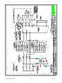
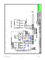
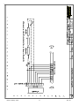
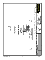
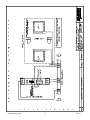
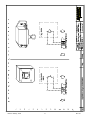
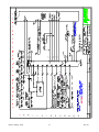
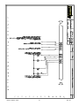
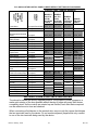
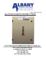
PART NUMBER 980076-0001
ALLSTAR STARTUP INSTRUCTIONS
ALLSTAR with ENCODER ELECTRICAL MANUAL
975-A OLD NORCROSS ROAD
LAWRENCEVILLE, GA 30045
(770) 338-5000 TEL
(770) 338-5034 FAX
(877) 925-2468 TOLL FREE
TABLE OF CONTENTS
•
•
•
•
WARRANTY
SAFETY PRACTICES
INSTALLATION
SETUP
• PRESSURE SWITCH ADJUSTMENT
• MAINTENANCE RECOMMENDED CHECKLIST
• ELECTRICAL SCHEMATICS AND TROUBLESHOOTING GUIDES
• POWER DIAGRAMS
• ENCODER WIRING
• REVERSING PHOTCELL DIAGRAM
• CONTACTLESS SAFETY EDGE PHOTCELL DIAGRAM
• MOTION DETECTOR DIAGRAM
• RADIO RECEIVER DIAGRAM
• FLOOR LOOP DIAGRAM
• PUSH BUTTON AND PULL CORD DIAGRAM
•
TROUBLESHOOTING GUIDE – PROGRAMS AEBLR, AEBQR
•
•
•
•
•
PLC LOGIC DIAGRAM – PROGRAM AEBLR, AEBQR
TROUBLESHOOTING GUIDE – PROGRAMS AEDXR
PLC LOGIC DIAGRAM – PROGRAM ANDXR
OPTIONAL ITEMS WIRING
RAPID RESET OPTION
3
4
5
6
7
8
9
11
12
13
14
15
16
17
18
19
20
21
23
24
NOTE
The attached electrical diagrams with these instructions are for reference
purposes only and may show wiring for options not supplied with the door. Please
refer to the actual schematics that are supplied with the control panel.
WARNING
DO NOT INSTALL, OPERATE, OR SERVICE THIS PRODUCT UNLESS YOU
HAVE READAND UNDERSTAND THE SAFETY PRACTICES, WARNINGS,
INSTALLATION, AND MAINTENANCE INSTRUCTIONS CONTAINED IN
THIS MANUAL.
Release January, 2006
2
Rev 4.0
Albany Door Systems
STATEMENT OF WARRANTY
ONE YEAR WARRANTY ON DOOR PANEL, MECHANICAL & ELECTRICAL
COMPONENTS
Albany Door Systems warrants to the original owner of the door that the door panel fabric,
mechanical and electrical components will be free of defects in material and workmanship for a period
of twelve (12) months from the date of shipment.
Only defects brought to the attention of Albany Door Systems during the warranty period will be
covered by his warranty.
Albany Door Systems will replace any component parts, which are found to be defective upon
inspection by an Albany Door Systems representative.
This warranty does not cover damage caused by collision or other abuse of the product. Adjustments
made to the Control Panel or to the mechanical operation of the door without the authorization of
Albany Door Systems will void this warranty.
The replacement provisions shall be the limit of Albany Door Systems responsibility under this
warranty Albany Door Systems shall not be responsible for any other losses or damages due to the
operation of any door or parts covered by this warranty.
No other oral or written representations made by Albany Door Systems or its agents are a part of this
warranty unless specifically set forth in writing by an authorized Albany Door Systems official.
THE ABOVE SET FORTH WARRANTY IS SELLER'S SOLE WARRANTY. SELLER MAKES NO OTHER
WARRANTY OF ANY KIND WHATSOEVER, EXPRESSED OR IMPLIED; AND ALL IMPLIED
WARRANTIES OF MERCHANTABILITY AND FITNESS FOR A PARTICULAR PURPOSE WHICH EXCEED
THE AFORESTATED OBLIGATION ARE HEREBY DISCLAIMED BY SELLER AND EXCLUDED FROM
THIS AGREEMENT.
USW-230.99
Release January, 2006
3
Rev 4.0
SAFETY PRACTICES
WARNING
THOROUGHLY READ THESE SAFETY PRACTICES PRIOR TO
INSTALLING, OPERATING, OR SERVICING A HIGH-SPEED, RAPID
ROLL® DOOR. FAILURE TO FOLLOW THESE SAFETY PRACTICES MAY
RESULT IN PROPERTY DAMAGE, PERSONNEL BODILY INJURY, OR
DEATH.
1. Do not operate a Rapid Roll® Door while you are under the influence of drugs or
alcohol.
2. Do not use the door if any parts appear to be broken or damaged.
3. Stay clear of the door while it is operating.
4. Keep hands and feet clear of the door at all times.
5. Do not drive through the door opening unless door is completely open.
6. Maintain a clear door opening at all times. Keep the door opening free of any
obstructions.
7. Remove power at the fused disconnect during all electrical or mechanical service.
OSHA requires a disconnect to be properly tagged and locked out during all
maintenance or service of equipment.
8. All electrical troubleshooting or service must be performed by a qualified electrician
or service person and must meet all applicable local, state, federal, and other
governing agency codes.
9. USE EXTREME CAUTION when it is necessary to service the control panel while
it is energized.
WARNING
CONTROL PANEL CONTAINS HIGH VOLTAGE. QUALIFIED ELECTRICAL
PERSONNEL SHOULD PERFORM THE FOLLOWING PROCEDURES ONLY.
WIRING MUST MEET ALL LOCAL, STATE, FEDERAL, INTERNATIONAL, OR
OTHER GOVERNMENT AGENCY CODES. FAILURE TO DO COULD RESULT IN
SERIOUS INJURY OR DEATH.
If you have any questions, please contact your local Albany service provider for
assistance. Otherwise contact Albany Door Systems 1-877-925-2468 for information on
your local distributor.
INSTALLATION
The following instructions are guidelines for electrically installing a generic Rapid® Roll Door with and
All★Star Drive System. Actual wiring may be different based on what options, special instructions,
special components, etc. were ordered with the door. Consult the electrical schematics that are supplied
with the door. These should be located inside the door’s control panel.
WARNING
CONTROL PANEL CONTAINS HIGH VOLTAGE. THE FOLLOWING PROCEDURES SHOULD
BE PERFORMED BY QUALIFIED ELECTRICAL PERSONNEL ONLY. WHENEVER
REMOVING POWER FROM THE CONTROL PANEL, WAIT AT LEAST 1 MINUTE PRIOR TO
SERVICING TO ALLOW CAPACITORS INSIDE THE FREQUENCY INVERTER TO DRAIN.
WIRING MUST MEET ALL LOCAL, STATE, FEDERAL, INTERNATIONAL, OR OTHER
GOVERNMENT AGENCY CODES. FAILURE TO DO COULD RESULT IN SERIOUS INJURY
OR DEATH.
NOTE
TO AID THE WIRING AND SERVICE OF ALL ELECTRICAL CIRCUITS, TAG OR LABEL ALL
WIRE ENDS DURING THE FOLLOWING ELECTRICAL INSTALLATION. HIGH VOLTAGE
POWER LEADS TO THE DRIVE UNIT MUST BE RUN IN A SEPARATE CONDUIT FROM THE
LOW VOLTAGE CONTROL WIRES.
1. Ensure the mechanical installation of the door is complete.
2. Mount the control panel at a serviceable height on the drive side of the door.
3. Run two electrical conduits from the control panel to the drive unit. Install a suitable junction box at
the drive unit for the motor leads. RUN ENCODER WIRE IN A SEPARATE CONDUIT! Install
a separate suitable junction box for the Encoder wiring.
4. Run conduits from the control panel to the side frame(s) to accommodate the door jamb photocell(s)
and the contactless safety edge (if supplied).
5. Install the pressure switch onto the bottom beam. Run the retractile cord to the control panel. Secure
the retractile cable to the drive side side frame cover using supplied cable clamp.
6. Install all the actuators and wire according to the electrical wiring diagrams.
7. Install a non-fused disconnect beside the control panel. The main supply to the All★Star drive
system can be wired from 208 VAC up to 600 VAC. The control panel is fused at 15 amps.
CAUTION
VERIFY ALL FIELD WIRING TO ENSURE TERMINAL CONNECTIONS ARE TIGHT AND
CORRECT. A FUSED DISCONNECT IS REQUIRED FOR EACH ALBANY DOOR AS A MEANS
OF DISCONNECTING INCOMING POWER FROM THE CONTROL PANEL. THIS
DISCONNECT IS NORMALLY SUPPLIED BY OTHERS.
Release January, 2006
5
Rev 4.0
SETUP - ALLSTAR™ DRIVE SYSTEM WITH ENCODER
1. Apply downward pressure on drive unit disengagement lever. Located on the backside of the drive
unit brake unit/pulse encoder enclosure to release the brake. While the brake is released, manually
move the door to the halfway point by pulling the door down. Allow brake to re-engage.
CAUTION
WHEN MANUALLY MOVING THE DOOR, GRAB HOLD OF THE ALUMINUM
OF THE BOTTOM BEAM. DO NOT PULL ON THE YELLOW, AS IT MAY TEAR.
2. Apply power to the control panel. Check for correct line voltage at FU1, FU2, and FU3 with a
voltmeter. Ensure the POWER LED’s on both the PLC and frequency inverter are lit. Also ensure
that the RUN LED is lit on the PLC.
CAUTION
ALL STEPS ASSOCIATED WITH SETTING THE DOOR LIMITS MUST BE
PERFORMED WITH EMERGENCY STOP BUTTON PULLED OUT.
3. Pull out the emergency stop button and put the system into the setup mode by pressing the SETUP
button (located on the control panel backplate). The RESET button on the face of the panel should
be illuminated. The 11-CR relay should also be energized also at this point. On the PLC the Y0, Y5
lights will be lit.
4. Using the UP/DOWN JOG DOOR switch located on the control panel backplate (small rocker
switch), jog the door in the up direction. If the door opens, then go to the next step. If the door
closes, then the phase rotation on the drive unit is backwards. Swap two of the three motor leads in
the panel to change the motor rotation (Terminals T11, T12, and T13).
NOTE
FOR THE FOLLOWING STEPS IT IS IMPORTANT TO ENSURE THE DOOR
IS MOVING WHEN THE RESET BUTTON IS PUSHED TO SET THE CLOSE
LIMIT. DO NOT RELEASE THE JOG SWITCH UNTIL DOOR HAS STOPPED
MOVING.
Setting the Door Limits
1. Press the SETUP button putting the door into the setup mode. The RESET should be illuminated at
this point.
2. Using the JOG SWITCH run the door down. While the door is closing, press the RESET button
when the door reaches the desired bottom limit position. The PLC will automatically sets this as the
doors’ bottom limit. The RESET button will go out also when you set this limit.
3. Put the system in the setup mode again by pressing the SETUP button.
4. Run the door up using the JOG SWITCH. While the door opening, press the RESET button when
the door reaches the desired top limit position. The PLC will automatically set this as the doors top
limit. The RESET light will also go out at this time.
Release January, 2006
6
Rev 4.0
5. Put the system in the setup mode by pressing the SETUP button.
6. Run the door to the halfway point using the JOG SWITCH. This time release the JOG SWITCH
and allow the door to come to a complete stop. Press the RESET button to clear the setup mode.
7. Push the green actuator button. As the door cycles, observe the open and close limits. Reset limits as
necessary to obtain exact desired limits (repeat steps 1-6 as necessary).
Pressure Switch Adjustment
1. Bump the rubber safety edge with your hand and observe input X5 on the PLC. If LED does not flash
off or was never on, then adjust the pressure switch. Flip RUN/STOP switch on PLC to the STOP
position to ensure that door is unable to be actuated while performing this adjustment. Remove cover
of pressure switch enclosure (Figure 1. Rotate white plastic screw on pressure switch counterclockwise with small screwdriver until LED turns off. Rotate screw clockwise until input LED turns
on. Turn another 1/4 turn. Test safety edge and observe LED (it should turn off momentarily
whenever pressure is applied to safety edge).
2. Flip RUN/STOP switch back to RUN
Figure 1
Final Checks
1. Check photocells for proper operation. Breaking the photocell beam should reverse the door
2. Check all actuators for proper operation and not sticking open.
Release January, 2006
7
Rev 4.0
Rapid Roll Door Maintenance Checklist
☼
Safety / Reversing Functions
Disconnect Switch
Crank Switch
Photoeyes
Reversing Edge
Emergency Stop
Warning Labels
C
C
C/A
C/A
C
C
220
230
☼
☼
☼
☼
☼
☼
☼
☼
☼
☼
☼
☼
Tension System
Steel/Rope Cables
Cable Attachment Bolts
Cable Drum
Spring / Spring Attachment
Balance System
C/L
C
C
C
C/A
Control Panel
Enclosure
Electrical Connections
Interlock
Timers
Warning Lights / Horns
C
C/A
C/A
C/A
C/A
Actuators
Pushbuttons
Pull Switches
Radio Controls
Motion Detectors
Photoeyes
Floor Loop Detector
C
C
C/A
C/A
C/A
C/A
Door Fabric / Sideframes
Door Fabric
Fabric Tracking
Bottom Beam End Brackets
Mounting Fasteners
Bearings & Locking Collors
Windbar System
Roll Support Rollers
Window / Vision Panels
Sideframe Locking Pins / Bolts
Hinges
Bottom Beam Profile
Doors Seals
Immersion Heaters
C
C/A
C
C/A
C/A
C/A
C/A
C
C
C
C
C
C
Drive Unit
Gearbox / Oil Level
Disengagement
Brake
Slipping Clutch
Friction Disc (,1/16”)
Limit Switches / Settings
Coupling
Chain Drive
C = CHECK
Release January, 2006
C/F
C/A
C/A
C/A
C/R
C/A
C/A
C/L
A= ADJUST
355
☼
570
☼
670
☼
X2
☼
☼
☼
☼
☼
☼
☼
☼
☼
☼
☼
☼
☼
☼
☼
☼
☼
☼
☼
☼
☼
PT800 RCA
☼
☼
☼
☼
☼
☼
☼
☼
☼
☼
☼
☼
☼
☼
☼
☼
☼
☼
☼
☼
☼
☼
☼
☼
☼
☼
☼
☼
☼
☼
☼
☼
☼
☼
☼
☼
☼
☼
☼
☼
☼
☼
☼
☼
☼
☼
☼
☼
☼
☼
☼
☼
☼
☼
☼
☼
☼
☼
☼
☼
☼
☼
☼
☼
☼
☼
☼
☼
☼
☼
☼
☼
☼
☼
☼
☼
☼
☼
☼
☼
☼
☼
☼
☼
☼
☼
☼
☼
☼
☼
☼
☼
☼
☼
☼
☼
☼
☼
☼
☼
☼
☼
☼
☼
☼
☼
☼
☼
☼
☼
☼
☼
☼
☼
☼
☼
☼
☼
☼
☼
☼
☼
☼
☼
☼
☼
☼
☼
☼
☼
☼
☼
☼
☼
☼
☼
☼
☼
☼
☼
☼
☼
☼
☼
☼
☼
☼
☼
☼
☼
☼
☼
☼
☼
☼
☼
☼
☼
☼
☼
☼
☼
☼
☼
☼
☼
☼
☼
☼
☼
☼
☼
☼
☼
☼
☼
☼
☼
☼
☼
☼
☼
☼
☼
☼
☼
☼
☼
☼
☼
☼
☼
☼
☼
☼
☼
☼
☼
☼
☼
☼
☼
☼
☼
☼
☼
☼
☼
☼
☼
☼
☼
☼
☼
☼
☼
☼
☼
☼
☼
☼
☼
F = FILL
8
☼
L = LUBRICATE
☼
R = REPLACE
Rev 4.0
Release January, 2006
9
Rev 4.0
A
c o m p a n y o f A lb a n y ln t e r n a t io n a l C o r p .
Release January, 2006
10
Rev 4.0
A
c o m p a n y o f A lb a n y ln t e r n a t io n a l C o r p .
Release January, 2006
11
Rev 4.0
A
c o m p a n y o f A lb a n y ln t e r n a tio n a l C o r p .
Release January, 2006
12
Rev 4.0
A
c o m p a n y o f A lb a n y ln t e r n a t io n a l C o r p .
Release January, 2006
13
Rev 4.0
Release January, 2006
14
Rev 4.0
A
c o m p a n y o f A lb a n y ln t e r n a t io n a l C o r p .
Release January, 2006
15
Rev 4.0
Release January, 2006
16
Rev 4.0
Release January, 2006
17
Rev 4.0
TROUBLESHOOTING GUIDE
For programs AEBLR, AEBQR
WARNING:
ALL ELECTRICAL TROUBLESHOOTING OR
SERVICE MUST BE PERFORMED BY A
QUALIFIED ELECTRICIAN OR SERVICE PERSON AND MUST MEET ALL
APPLICABLE LOCAL, STATE, FEDERAL, AND OTHER GOVERNING AGENCY
CODES. EXERCISE EXTREME CAUTION WHEN IT IS NECESSARY TO SERVICE
THE CONTROL PANEL WHILE IT IS ENERGIZED.
The POWER and RUN green LED’s on the PLC must be on. If not, check for 120V power to terminals
L&N. If no power is present, de-energize control panel and check main disconnect and all control panel
fuses. Fuses FU1 and FU2 are the main power supply to the panel. Fuses FU3 & FU4 are for 120 VAC
power supply to the PLC. At least one, red input LED’s on the PLC should be on. If not, ensure the
EMERGENCY STOP button is pulled out. If no inputs turn on, check for missing jumpers and/or switch
wiring in series with the EMERGENCY STOP button (i.e. crank/chain hoist switch, thermal overloads,
inertia brake contact, etc.).
PLC INPUTS
(X0-X7)
INPUTS (“IN” LED’S)
DESCRIPTION
0
Encoder Position Signal – Channel B. Flickers when doors runs.
1
Encoder Position Signal – Channel A. Flickers when doors runs.
2
3
4
5
6
7
Release January, 2006
Shutdown Devices. Should be lit unless a shutdown device (E-Stop,
Crank Switch, ect) or SRD is activated
Setup. Should be lit unless the setup button has been tripped.
Actuator Impulse Open. Will come on for as long as the actuator has
been activated. If on continuously, check actuators.
Safety Devices. Photocell, CSE and Reversing edge contacts are
wired in series with this input. Should be on unless a safety device is
activated. (N/C)
Interlock. Needs be lit to enable door operation, or jumped out if no
interlock is being using.
Reset Button. Will Reset the door when activated.
18
Rev 4.0
Release January, 2006
19
Rev 4.0
A
c o m p a n y o f A lb a n y ln t e r n a t io n a l C o r p .
TROUBLESHOOTING GUIDE
For program AEDXR
WARNING:
ALL ELECTRICAL TROUBLESHOOTING OR
SERVICE MUST BE PERFORMED BY A
QUALIFIED ELECTRICIAN OR SERVICE PERSON AND MUST MEET ALL APPLICABLE
LOCAL, STATE, FEDERAL, AND OTHER GOVERNING AGENCY CODES. EXERCISE
EXTREME CAUTION WHEN IT IS NECESSARY TO SERVICE THE CONTROL PANEL WHILE
IT IS ENERGIZED.
The POWER and RUN green LED’s on the PLC must be on. If not, check for 120V power to terminals
L&N. If no power is present, de-energize control panel and check main disconnect and all control panel
fuses. Fuses FU1, FU2, and FU3 are the main power supply to the panel. Fuses FU4 & FU5 are for
120 VAC power supply to the PLC. At least one, red input LED’s on the PLC should be on. If not,
ensure the EMERGENCY STOP button is pulled out. If no inputs turn on, check for missing jumpers
and/or switch wiring in series with the EMERGENCY STOP button (i.e. crank/chain hoist switch,
thermal overloads, inertia brake contact, etc.).
PLC INPUTS (X0-X17)
INPUTS
(“IN” LED’S)
DESCRIPTION
0
Encoder Position Signal – Channel B. Flickers when doors runs.
1
Encoder Position Signal – Channel A. Flickers when doors runs.
2
Shutdown Devices. Should be lit unless a shutdown device (E-Stop, Crank Switch,
ect) or SRD is activated
3
Setup. Should be lit unless the setup button has been tripped.
4
Impulse Open. Will come lit for as long as the actuator has been activated. If on
continuously, check actuators.
5
Safety Devices. Photocell, CSE and Reversing edge contacts are wired in series
with this input. Should be lit unless a safety device is activated. (N/C)
6
7
10
11
12
13
14
15
16
17
Interlock. Needs be lit to enable door operation, or jumped out if no interlock is being
using.
Reset Button. Will Reset the door when activated.
Not Used.
Actuator Full Height Open. Will come lit for as long as the actuator has been
activated. If on continuously, check actuators.
Actuator Close. Will come on for as long as the actuator has been activated. If on
continuously, check actuators.
Auto/Manual. Jump for non-auto. (Will be lit when in Manual mode)
Actuator Mid Height Open. Will become lit for as long as the actuator has been
activated. If on continuously, check actuators.
NOT USED.
NOT USED
Extra Reversing Photocells. Will be lit (N/C). If no photocells are being used,
should be jumped out for normal door operation.
Release January, 2006
21
Rev 4.0
A
c o m p a n y o f A lb a n y ln t e r n a tio n a l C o r p .
Release January, 2006
22
Rev 4.0
A
c o m p a n y o f A lb a n y ln t e r n a tio n a l C o r p .
Release January, 2006
23
Rev 4.0
JUMPER
NUMBER
JUMPER
FUNCTION
/FIELD DEVICE
BEING
BYPASSED
PLC AND ALLSTAR CONTROL PANEL JUMPER DEFAULT SETTINGS BY DOOR MODEL
CONTROL PANEL TERMINAL NUMBERS
MODELS
230, 570,
670 W
ALLSTAR
LIMITS
Crank/Hoist
Thermal
Jumper1Crank/Hoist
Jumper2
XC0, XC1
XC0, XC1
XC0, XC1
Disengagement/Inertial
Brake
Jumper3
XC2, XC3
XC2, XC3
XC2, XC3
XC2, XC3
Panel E-Stop
Field E-Stop1
Field E-Stop2
Spare1
Spare2
Jumper4
Jumper5
Jumper6
Jumper7
Jumper7B
XC4, XC5
XC5, XC6
XC6, XC7
XC7, XR1
XC4, XC5
XC5, XC6
XC6, XC7
XC7, XR1
Rapid Reset
Setup Button
Open Slowdown Limit
Close Slowdown Limit
Photocell PC-11
Photocell PC-12
Jumper8
Jumper9
Jumper10
Jumper11
Jumper12
Jumper13
XC4, XC5
XC5, XC6
XC6, XC7
XC7, XR1
XR1,
0VDC
XR1, 24V+
XC0, XL1
XC0, XL2
XXXX
XXXX
XR1, 0VDC
XR1, XR0
XC0, XL1
XC0, XL2
XC4, XC5
XC5, XC6
XC6, XC7
XC7, XR1
XR1,
0VDC
XR1, XR0
XC0, XL1
XC0, XL2
XP3, XP2
XP3, XP2
Pneumatic Reversing
Edge
Jumper14
Electric Reversing Edge
Interlock1
Interlock2
Reset Button
Special
Defeat Close Timer
Mid Height Limit1
Mid Height Limit2
Photocell PC-13
Photocell PC-14
Jumper15
Jumper16
Jumper17
Jumper18
Jumper19
Jumper20
Jumper21
Jumper22
Jumper23
Jumper24
XP3, XP2
MODELS
230, 570,
670 W
ALLSTAR
ENCODER
MODELS
230, 570,
670 W PLC
CONTROL
XP3, XP2
MODEL
RE-COILAWAY
XP2, XP1
XP1, X5
ON PLC
XR0, XQ2
XQ2, XQ1
XP1, X5
ON PLC
XR0, XQ2
XQ2, XQ1
XP1, X5 ON
PLC
XR0, XQ2
XQ2, XQ1
XR0, XQ2
XQ2, XQ1
XXXX
XR0, XL4
XXXX
XXXX
XR0, XL4
XR0, XL5
XR0, XP5
XP5, XP4
XXXX
XXXX
XR0, XP5
XP5, XP4
XR0, XL4
XR0, XL5
XR0, XP5
XP5, XP4
XR0, XL4
XR0, XL5
XR0, XP5
XP5, XP4
INSTRUCTIONS FOR FIELD INSTALLER
The above list shows the factory supplied jumpers. The purpose of these jumpers is to
make quick startup of the door possible without having to begin with every field device
completely wired. As the controls are started up and verified, each field device required
can be added one at a time and checked.
When connecting a field device to the terminal strip, remove only the jumper that bridges
the two terminals used by the device. Do not remove adjacent jumpers that only connect
to one of the two terminals being used by the device.
Release January, 2006
24
Rev 4.0
Release January, 2006
25
Rev 4.0
RAPID RESET OPTION
The new accelerometer switch is a vibration switch calibrated to trip when a lateral impact on the beam
causes a momentary force of acceleration on the bottom beam exceeding 1G. Because of the momentary
nature of this switch, it cannot detect the final condition of the door fabric after impact. Due to the nature
of the mechanical design, it is critical that the door not be electrically operated until the door blade is
completely restored. Failure to reset door fabric back into the tracks will result in considerable damage
to the door blade fabric, and may void warranty.
1. Upon impact, a shock sensor located in the bottom beam will signal the door to stop
immediately. While it is preferable for the driver to stop upon impact, it is not necessary. The
door will not be damaged if the driver continues through the opening.
2. A blinking amber light on the control panel will indicate the door is in need of being reset. A
sticker on the control panel indicates the steps necessary for reset. They are as follows:
• Return the fabric completely onto the side frame guide. This is accomplished by either
moving the bottom bar manually back and forth, or the side frame covers may be opened.
• Push and hold the reset button for 3 seconds until the light goes out. The door is now able
to operate normally.
1. Enclosure Switch
2. Air Nipple
3. Strain Relief
4. Bracket, Accel Switch
5. Switch, Accelerometer
6. Tube, Air
7. Switch Pressure
8. Bracket, Pneumatic Switch
9. Screw PH, M3 x 8
10. Nut #4
11. Screw 4-40 x 1.50
Release January, 2006
Figure
26 2
Rev 4.0
Notes:
DOCUMENT TITLE
DOCUMENT NUMBER
Allstar with Encoder Control Panel Manual
980076-0001
DOOR MODEL(S)
ISSUE DATE
2006-01-13
ELECTRONIC FILE
Allstar with EncoderV4.DOC
ASSEMBLY
CONTROLS
REPLACES
ORIGINATOR
Rick Walton
MANAGER
APPROVAL/DATE
Release January, 2006
27
Allstar Electrical Manual Encoder V2.5
Rev 4.0