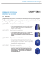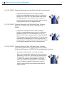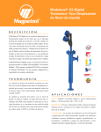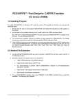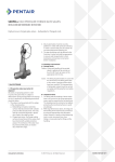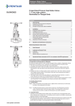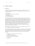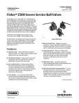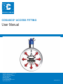
1
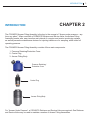
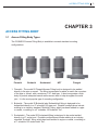
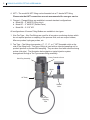
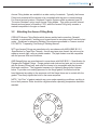
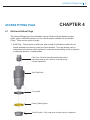
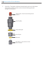
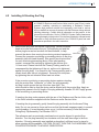
COSASCO® ACCESS FITTING
User Manual
Rohrback Cosasco Systems, Inc.
11841 E. Smith Avenue
Santa Fe Springs, CA 90670
Tel: (562) 949-0123
(800) 635-6898
Fax: (562) 949-3065
E-mail: [email protected]
www.cosasco.com
740073 Rev.-D
COSASCO® is a registered trademarks of Rohrback Cosasco Systems, Inc.
No part of this manual may be reproduced or transmitted in any form or by any means, electronic
or mechanical, including photocopying and recording, for any purpose, without the express written
permission of Rohrback Cosasco Systems, Inc.
i
IMPORTANT INSTRUCTIONS
Rohrback Cosasco Systems is committed to providing the safest and highest quality products, services, and
training for the industries it serves. We are committed to ensuring that all users of our equipment work safely
and efficiently. Fully anticipating the infinite variety of conditions that may be encountered in the field would
be impossible, but we have designed this user manual to emphasize safe working practices and, as much as
possible, to convey the full benefit of our knowledge and collective experience in the use of the COSASCO
Access Fittings. This user manual is not meant to be a sole source of instruction and is intended only for an
overview of COSASCO Access Fittings and installation of the carrier plug and protective cover on the Access
Fitting on non-pressurized lines. A COSASCO Retriever and Service Valve must be used for the installation
and removal of carrier plug from Access Fittings on pressurized lines. Because these tools are used in a broad
range of environments and applications, it is important that the owner and operation personnel have been
assessed, certified, and deemed competent in all safety, work management and additional risk assessment
requirements in the application of this procedure.
Installing, operating or maintaining a Rohrback Cosasco Systems high
pressure retrieval tool improperly could lead to serious injury or death from a
surge of pressure into the retriever during retrieval (Pistoning). Comply with
all information on the product, in this user manual, and in Cosasco System
Safety Awareness Training that apply to the product. Do not allow untrained
or inexperienced personnel to work with this product. Use COSASCO parts
and work procedures specified in this user manual.
BE SURE ALL PERSONNEL READ AND FOLLOW THE INSTRUCTIONS
IN THIS USER MANUAL AND ALL PRODUCT WARNINGS.
Product Owners (Purchasers):
1. Use the correct product for the environment and pressures present. If you are unsure, discuss
your needs with your RCS representative.
2. Inform, educate, and train all personnel in the proper installation, operation, and maintenance of
this product.
3. To ensure proper performance, only competent, field experienced and trained personnel should
install, operate, repair and maintain this product.
4. Save this user manual for future reference.
Product Operation Personnel:
1.
2.
3.
4.
5.
6.
7.
8.
Read and understand all instructions and operating procedures for this product.
Follow all warnings, cautions, and notices marked on, and supplied with, this product.
Follow all instructions during the installation, operation, and maintenance of this product.
To prevent personal injury, ensure that all components are in place prior to and during
operation of the product.
If you do not understand an instruction, or do not feel comfortable following the instructions,
contact an RCS service technician for clarification or assistance.
If this user manual is not the correct user manual for your RCS product, contact RCS at
+1-562-949-0123 and RCS will provide you with the requested manual.
Use only replacement parts specified by RCS. Unauthorized parts and procedures can
affect this product’s performance, safety, and invalidate the warranty. “Look-a-like”
substitutions may result in improper operation and may result in serious injury or death.
Save this user manual for future reference.
ii
NOTICE
Information provided in COSASCO® Access Fitting User Manual should not be considered as all
encompassing or suitable for all situations, conditions or environments. Each individual and the organization
he/she represents is responsible for implementing training and its/his/her own safety/injury/illness prevention
program in connection with this user manual, and should consult with their respective legal, medical or other
advisors as to the suitability of using the information in connection with this user manual.
Application of information furnished by this user manual does not guarantee that the information furnished will
meet applicable USA (including OSHA), United Kingdom, or any other country’s health or safety standards or
requirements or, by implementing any of the programs, that you or your company will be compliant with such
rules and regulations.
Rohrback Cosasco Systems, Inc., and its affiliates assume no liability arising from the use of, or reliance on
the information provided in this user manual. Always seek the advice of your legal, medical or other advisors
before using this information in this user manual.
NEITHER ROHRBACK COSASCO® SYSTEMS, INC., NOR ITS INSTRUCTORS ARE RESPONSIBLE
FOR THE USE BY ANY TRAINEE OR ORGANIZATION OF THIS USER MANUAL OR ANY INFORMATION
CONTAINED HEREIN. ANY PERSON OR ORGANIZATION UTILIZING THIS USER MANUAL, FOR ANY
PURPOSE, DOES SO AT ITS/HIS/HER OWN RISK.
iii
Table of Contents
Chapter 1 Safety Warnings........................................................................1
Chapter 2 Introduction...............................................................................3
Chapter 3 Access Fitting Body.................................................................5
3.1 Access Fitting Body Types.................................................................................5
3.2 Attaching the Access Fitting Body......................................................................7
Chapter 4 Access Fitting Plug..................................................................9
4.1 Solid and Hollow Plugs......................................................................................9
4.2 Installing & Orienting the Plug..........................................................................11
Chapter 5 Pressure Retaining/Protective Covers .................................13
4.1 Overview..........................................................................................................13
4.2 Cover and Installation & Removal...................................................................15
iv
SAFETY WARNINGS
SAFETY WARNINGS
CHAPTER 1
The Cosasco Access assembly system has been in use for over 30 years, and has proven itself to be
safe and reliable. However, when working with any high pressure system, safety must be a primary
consideration.
It is imperative that the following safety warnings are taken into important consideration
before and during use of Retrieval Equipment. Safety warnings in this document are to
ensure precautions are taken for all procedures where there are risks involved. Failure
to follow these warnings could result in serious injury or death.
1. Safe operation under pressure requires 2 experienced and competent operators.
2. Do not use retrieval equipment unless you have been trained and are competent in its safe
operation.
3. If it has been longer than 90 days since your last operation, you should review the relevant Work
Instruction and complete an operation on a pressurized test rig.
4. Make sure you have complied with all plant safety requirements and environmental regulations.
5. Identify the media, its pressure and temperature. Review material safety data information on the
media prior to operation.
6. Insure you have all the required safety equipment for the given media, “i.e. hard hat, safety
glasses, protective clothing, safety gloves, respirator, spill safety equipment, etc...
7. Any actions which could vary system pressure such as surges caused by opening and closing of
valves and chokes should be delayed until completion of retrieval operations.
8. Ensure you have enough clearance for safe operation. Note wind direction prior to starting
operations involving hazardous products.
9. WARNING: Surface temperature may be hot. Contact may cause burn.
10. WARNING: Do not exceed equipment specified pressure rating. Over-pressurization can cause
equipment to fail/burst posing a variety of safety hazards.
1
2
COSASCO® ACCESS FITTING USER MANUAL
11. WARNING: Do not apply a load of more than 150 pounds, perpendicular to the Access Fitting
thread axis, on any access fitting attachment to prevent breakage from bending stresses.
12. WARNING: Heavy Pressure Retaining Covers are available as an optional means of protecting
Access Fitting external threads from damage and add an extra safety pressure layer in the event
that a fitting may leak.
INTRODUCTION
CHAPTER 2
INTRODUCTION
The COSASCO Access Fitting Assembly is the key to the concept of “Access under pressure – any
time, any place”. When used with a COSASCO Retriever and Service Valve, the Access Fitting
Assembly permits safe, easy insertion and retrieval of corrosion and erosion monitoring systems
as well as preventive maintenance devices for injecting inhibitors or for sampling, while under full
operating pressure.
The COSASCO Access Fitting Assembly consists of three main components:
1. Pressure Retaining/Protective Cover
2. Carrier Plug
3. Access Fitting Body
Pressure Retaining/
Protective Cover
Carrier Plug
Access Fitting Body
For “Access Under Pressure”, a COSASCO Retriever and Service Valve are required. One Retriever
and Service Valve may be used to maintain a number of Access Fitting Assemblies.
3
4
COSASCO® ACCESS FITTING USER MANUAL
ACCESS FITTING BODY
CHAPTER 3
ACCESS FITTING BODY
3.1
Access Fitting Body Types
The COSASCO Access Fitting Body is available in several standard mounting
configurations:
Flarweld
Buttweld
Socketweld
NPT
Flanged
1. Flarweld – The model 50 Flarweld Access Fitting body is designed to be welded
directly to the pipe or vessel. The fitting incorporates a radius to match the curvature
of the pipe or vessel, with a maximum 1/16” weld gap. It also incorporates a thick
body to provide adequate branch reinforcement area to help strengthen the weld
joint. It is the most popular type of mounting configuration.
2. Buttweld – The model 52 Buttweld (aka. Buttweldolet) fitting is designed to be
buttwelded directly to a 2” schedule 160 pipe end. Possible configurations include
welding to an industry standard “Weldolet” fitting, which has been welded to a pipe
or vessel, or welding to a 2” schedule 160 buttweld ‘Tee”.
3. Socketweld – The model 53 Socketweld fitting is designed to be socket welded
directly to a 2” socket end. Possible configurations include welding to an industry
standard “Sockolet” fitting, which has been welded to a pipe or vessel, or welding to
a 2” schedule 160 socket weld ‘Tee”.
5
6
COSASCO® ACCESS FITTING USER MANUAL
4. NPT – The model 54 NPT fitting can be threaded into a 2” female NPT fitting.
Please note that NPT connections are not recommended for sour gas service.
5. Flanged – Flanged fittings are available in several standard configurations:
a. Model 56 – 2” ANSI RJ (Ring Joint)
b. Model 57 – 2” ANSI RF (Raised Face)
c. Model 58 – 2-1/16” API
All configurations of Access Fitting Bodies are available in two types:
1. Non-Tee Type – Non-Tee fittings are used for all corrosion monitoring devices which
do not require injection or sampling of the process fluid, such as coupon holders,
Microcor probes, hydrogen probes, etc.
2. Tee Type – Tee fittings incorporate a ¼”, ½”, ¾”, or 1” NPT threaded outlet on the
side of the fitting body. This type of fitting is used with an injection/sampling nut for
product injection or process fluid sampling. They are also used with sand monitoring
probes (old style). The illustration below depicts a typical injection system
arrangement through a Tee Type access fitting assembly.
Solid Plug Assembly
Heavy Protective Cover
Nipple
A/F Body
Shut-off
Valve
Injection /
Sampling
Tube
ACCESS FITTING BODY
Access Fitting bodies are available in a wide variety of materials. Typically, the Access
Fitting body material will be chosen to be compatible with the pipe or vessel material.
For severe service locations, Rohrback Cosasco Systems offers a patented type CR
“Corrosion Resistant” option on all Access Fitting bodies. This option provides internal
threads and seal areas of Hastelloy C276, while the Access Fitting body remains a
material compatible to the pipe or vessel.
3.2
Attaching the Access Fitting Body
COSASCO Access Fitting Bodies which have a welded end connection, (flarweld,
buttweld, or socketweld), welding must be performed in accordance with local and plant
codes. Guidelines for preparing Welding Procedures are available in Cosasco manual
P/N 740074, “Trepanning, Positioning & Welding Manual”.
NPT type Access Fittings are manufactured in accordance with ANSI/ASME B1.20.1
-Specification for Taper Pipe Threads. As with any taper pipe thread, the joint must be
made up wrench tight, using a suitable sealant. The pipe sealant must be compatible
with the process fluid and conditions.
ANSI flange fittings are manufactured in accordance with ANSI B16.5 – Specification for
Flanges and Flanged Fittings. Flange gaskets and stud-and-nut sets are not provided
with the Access Fitting body, and must be chosen to be compatible with the process
fluids and conditions. The suggested sequence for tightening flange bolts is shown
below. To provide even sealing pressure on the flange gasket, the bolts should be
hand tightened according to the sequence until the flange faces are in contact with the
gasket. Then firmly tighten the bolts in the same sequence.
NOTE: “Hot Flow” of gasket material may occur under operating conditions, resulting in
loss of bolt pressure. Bolts should be retightened after operating temperature has been
reached.
1
5
8
3
4
7
6
2
7
8
COSASCO® ACCESS FITTING USER MANUAL
ACCESS FITTING PLUG
ACCESS FITTING PLUG
4.1
CHAPTER 4
Solid and Hollow Plugs
The Access Fitting plug is the retrievable “carrier” which holds the device (coupon
holder, probe, chemical injection nut, etc.) which may be installed into the Access
Fitting. There are two types of plugs:
1. Solid Plug – This plug has a solid bore, and is used to hold devices which do not
require external connections, such as coupon holders. They are always used in
conjunction with devices which interface to a side-tee access fitting, such as injection
or sampling systems, or sand probes.
Pipe Plug - Protects internal threads and provides
secondary backup seal. Must be removed during
retrieval operations.
Solid Plug Body
O-ring Seal
Primary Packing Seal
Solid Plug Nut - Only used when no other device is attached.
9
10 COSASCO® ACCESS FITTING USER MANUAL
2.
Hollow Plug – This plug has a hollow bore through the plug, and is used to hold devices
which require an external connection, such as corrosion monitoring probes and
hydrogen monitoring probes.
Thread Protector – Must be removed during retrieval
operations.
Hollow Plug Body
Primary Packing seal
Hollow Plug Nut
Device seal
Bore Seal Nut – Only used when no other
device is attached.
ACCESS FITTING PLUG
4.2
Installing & Orienting the Plug
WARNING
1.
A COSASCO Retriever and Service Valve must be used if line is under
pressure. Installing, operating or maintaining a Rohrback Cosasco
Systems high pressure retrieval tool improperly could lead to serious
injury or death from a surge of pressure into the Retriever during retrieval
(causing pistoning). Comply with all information on the product, in the
relevant work instruction, and in COSASCO System Safety Awareness
Training that apply to the product. Do not allow untrained or inexperienced
personnel to work with these products. Use COSASCO parts and work
procedures specified in the work instruction.
Remove the plug from the Access Fitting body. Loosen the Allen
head set screw and remove the nut. The solid plug nut and the
hollow plug bore seal nut are both left hand threads, to help
prevent the device from coming loose during retrieval operations.
Connect the corrosion monitoring or preventing device to the plug
assembly (with left-hand threads). See specific work instructions
for each monitoring/preventing device. After initial packing
contact, compress the packing by tightening the device up to
1/4 turn more. Please note that the Primary Packing seal is not
compressed by the tightening of the nut, as the nut is tightened
against the plug body. It is normal for the Primary packing seal to
remain loose after the nut is tightened. Securely lock into place
by tightening the anti-vibration Allen head set screw.
Index Notch
If the corrosion monitoring or preventing device requires orienting
with the product flow, “reference” or “index” the plug assembly
by filing a notch across the top of the hex (see right). The
notch should be filed so that the device can be aligned with the product flow. Apply an
appropriate grease to the full length of the plug assembly threads. DO NOT apply grease
to the monitoring or preventing device.
If inserting the plug under pressure with the use of the Retriever and Service Valve, refer
to the Work Instruction supplied with the Retriever and/or Service Valve
If inserting the plug manually, gently thread the plug assembly into the Access Fitting
body. Do not use excessive force and be sure that the threads engage properly to prevent
cross-threading. If cross-threading does occur, it will be necessary to use the Access
Fitting Body Tap Assembly, Part Number 125111.
The reference mark as previously mentioned must now be aligned to product flow
direction. Turn the plug assembly hex clockwise until the mark does align to the flow
direction. If the plug assembly was installed as described, sufficient room for travel to
allow orienting will be available. CAUTION: DO NOT TURN THE PLUG ASSEMBLY HEX
COUNTERCLOCKWISE TO ACHIEVE ORIENTATION!
11
12 COSASCO® ACCESS FITTING USER MANUAL
WARNING
DO NOT TURN THE PLUG ASSEMBLY HEX COUNTERCLOCKWISE TO
ACHIEVE ORIENTATION! This will unseat the primary packing seal from the
internal sealing face of the access fitting and leakage will occur!
Make sure the fitting is clean and dry, and install the thread protecting pipe plug into the top of the
plug. Liberally grease the 1/4” stainless steel pipe plug and install into the solid plug hand tight.
Hollow plug assemblies use a red plastic pipe plug, therefore greasing is unnecessary.
PRESSURE RETAINING/PROTECTIVE COVERS
PRESSURE RETAINING/
PROTECTIVE COVERS
5.1
13
CHAPTER 5
Overview
Pressure Retaining and Protective covers thread onto the external thread on the Access Fitting body.
The Pressure Retaining Cover acts as a secondary process containment and includes Bleed Valve
and Pressure Gauge. The Protective Covers protect the external thread and external seal area on the
Access Fitting body from damage. Several configurations are available:
(-1) P/N 122734
Heavy Protective Cover without Hole
• A non-pressure retaining steel cover for use with devices
that do not require routine access to the plug assembly
(such as coupon holders).
(-2) P/N 122732
Heavy Protective Cover with Hole
• A non-pressure retaining steel cover with an access hole
on the top for use with devices that require routine
access to the plug assembly (such as corrosion monitoring
probes).
(-5) P/N 206436
Polycarbonate Cover without Hole
• A non-pressure retaining polycarbonate cover for use
with devices that do not require routine access to the plug
assembly (such as coupon holders). This is a lighter duty
alternative to the standard steel cover.
(-6) P/N 206435
Polycarbonate Cover with Hole
• A non-pressure retaining polycarbonate cover with an
access hole on the top for use with devices that require
routine access to the plug assembly (such as corrosion
monitoring probes). This is a lighter duty alternative to
the standard steel cover.
14 COSASCO® ACCESS FITTING USER MANUAL
(-10) P/N 740090 Pressure Retaining Cover with Bleed Valve & Pressure Gauge
•
A pressure retaining steel cover with an integral
bleed valve and pressure gauge rated for a maximum
pressure of 10,000 PSI. The bleed valve must always
be opened prior to removing the cover. If pressure
cannot be bled, the cover must be left in place and the
fitting repaired with the line depressurized.
(-11) P/N 740093 Pressure Retaining Cover With Bleed Valve, Pressure
Gauge and ½” NPT Center Hole for Standard Probe
Adapter
•
A pressure retaining steel cover with an integral
bleed valve and pressure gauge rated for a maximum
pressure of 2500 PSI. This cover has a ½” NPT in
the top of the cover to accommodate a standard (2500
PSI) pressure retaining Probe Adapter. The bleed valve
must always be opened prior to removing the cover. If
pressure cannot be bled, the cover must be left in place
and the fitting repaired with the line depressurized.
(-12) P/N 740095 Pressure Retaining Cover With Bleed Valve, Pressure
Gauge and Center Hole for High Pressure Probe Adapter.
Must use High Pressure (10,000 PSI) Probe Adapter with this Cover.
•
A pressure retaining steel cover with an integral
bleed valve and pressure gauge rated for a maximum
pressure of 10,000 PSI. This cover has center hole in
the top of the cover to accommodate a high pressure
(10,000 PSI) retaining Probe Adapter. The bleed
valve must always be opened prior to removing the
cover. If pressure cannot be bled, the cover must
be left in place and the fitting repaired with the line
depressurized.
PRESSURE RETAINING/PROTECTIVE COVERS
5.2
15
Cover Installation & Removal
All pressure retaining and protective covers are supplied with an internal o-ring. Make certain that the
o-ring is fitted into the internal groove. Make certain the flat area (sealing surface) above the external
threads on the access fitting body is clean and dry. Lubricate the threads with an appropriate grease,
and thread the cover onto the fitting. Non-pressure retaining covers can be installed hand-tight.
Pressure retaining covers should be tightened with a spanner wrench.
If pressure retaining covers are used, be sure all pressure is bled from the cover before removal. If it
is not possible to bleed pressure, the cover should not be removed until the line is depressurized. To
remove the cover, simply unthread the cover from the fitting, using a spanner wrench to loosen the
cover, if required.
16 COSASCO® ACCESS FITTING USER MANUAL
NOTES
NOTES 17
NOTES
Rohrback Cosasco Systems, Inc.
11841 E. Smith Avenue
Santa Fe Springs, CA 90670
Tel: (562) 949-0123
(800) 635-6898
Fax: (562) 949-3065
E-mail: [email protected]
www.cosasco.com