1
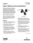
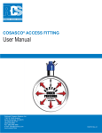
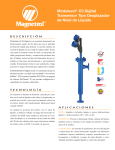
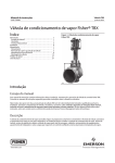
Instruction Manual
Z500 Valve
D103803X012
April 2015 - rev B
Fisherr Z500 Severe Service Ball Valves
Contents
Figure 1. Fisher Z500 Severe Service Ball Valve
Introduction . . . . . . . . . . . . . . . . . . . . . . . . . . . . . . . . . 1
Scope of Manual . . . . . . . . . . . . . . . . . . . . . . . . . . . . . 1
Description . . . . . . . . . . . . . . . . . . . . . . . . . . . . . . . . . 1
Specifications . . . . . . . . . . . . . . . . . . . . . . . . . . . . . . . 1
Installation . . . . . . . . . . . . . . . . . . . . . . . . . . . . . . . . . . . . 5
Operation . . . . . . . . . . . . . . . . . . . . . . . . . . . . . . . . . . . 7
Maintenance . . . . . . . . . . . . . . . . . . . . . . . . . . . . . . . . . . 8
Troubleshooting . . . . . . . . . . . . . . . . . . . . . . . . . . . . . 9
Packing Replacement . . . . . . . . . . . . . . . . . . . . . . . 10
Actuator Mounting . . . . . . . . . . . . . . . . . . . . . . . . . 13
Parts Ordering . . . . . . . . . . . . . . . . . . . . . . . . . . . . . . . . 18
Parts List . . . . . . . . . . . . . . . . . . . . . . . . . . . . . . . . . . . . . 18
X1200
Introduction
Scope of Manual
This instruction manual provides installation, operation, maintenance, and parts information for the Fisher Z500
Severe Service Ball Valve (see figure 1).
Do not install, operate, or maintain Z500 valves without being fully trained and qualified in valve, actuator, and
accessory installation, operation, and maintenance. To avoid personal injury or property damage, it is important to
carefully read, understand, and follow all the contents of this manual, including all safety cautions and warnings. If you
have any questions about these instructions, contact your Emerson Process Management sales office before
proceeding.
Description
The Z500 severe service ball valve is a split body bolted design, full or reduced port, with a blowout proof stem. It can
be lever operated, gear operated, or actuated. The Z500 severe service ball valve line is a simplistic two-piece floating
ball design with integral metal seat meant to provide tight metal seating shutoff in high temperature, high pressure,
corrosive, and erosive applications across all industries.
Specifications
Specifications for these valves are shown in table 1.
www.Fisher.com
Instruction Manual
Z500 Valve
D103803X012
April 2015 - rev B
Table 1. Specifications
Valve Sizes
Z500: NPS J 1/2, J 3/4, J 1, J 1-1/2, J 2, J 3,
J 4, J 6, J 8, J 10, J 12, J 14, J 16, J 18, J 20,
J 24, J 26, J 28, J 30 and, J 36
Maximum Working Pressures(1)
Forged Steel Valves: Consistent with applicable
pressure-temperature ratings in table 2 per ASME
B16.34, but do not exceed the material temperature
capabilities shown below.
Shutoff Classification(1)
Z500: Valves are tested to API 598 in the preferred
flow direction.
Class V type B per FCI 70-2 in reverse flow in
bi-directional design (Must be specified). For other
shutoff requirements, please contact your Emerson
Process Management sales office
Construction Materials
See table 3
Temperature Capabilities(1)
Welded and Threaded Ends: SA105 - 800_F, F22
1000_F, F91 1200_F, F316 1400_F
Flanged End Connections: SA105 - 600_F, F22 800_F,
F91 1000_F, F316 1000_F
Packing Constructions
Carbon Steel Valve Bodies: Wire reinforced graphite
stem packing, AISI 4130 nitrided packing gland
Stainless Steel: Wire reinforced graphite stem
packing, 316 SST nitrided packing gland
Dimensions
Contact your Emerson Process Management sales
office
Standard Flow Direction
Preferred Flow Direction: Preferred flow for optimal
sealing is forward into the integral seat
Flow Coefficients
Contact your Emerson Process Management sales
office
Maximum Ball Rotation
90 degrees
Actuator Mounting
The preferred mounting orientation is vertical. Other
orientations are acceptable
Approximate Weight
Contact your Emerson Process Management sales
office
Options
J Reduced port, J Double reduced ports,
J Expanded outlet, J Scraper seats, J HVOF
coating options, J Bi-directional sealing, J High
cycle constructions, J Lockouts, J Spray and fused
coatings
1. The pressure/temperature limits in this bulletin, and any applicable code or standard limitation, should not be exceeded.
2
Instruction Manual
Z500 Valve
D103803X012
April 2015 - rev B
Table 2. Valve Body Materials, End Connections, and Ratings
Ratings
Bore
Size, NPS
End Connection
Valve Body Materials
1/2
0.65
3/4
1
1-1/2
1
1.15
1-1/2
2
Buttweld, Socketweld, FNPT,
RF, RTJ
2-1/2
1-1/2
1.5
2
2
2-1/2
3
Buttweld, RF, RTJ
2
Buttweld, Socketweld, FNPT,
RF, RTJ
2-1/2
3
4
Buttweld, RF, RTJ
3
CL150 through 1500
3
4
SA105, F22, F91, and F316
6
4
6
8
4
6
6
8
8
10
10
10
12
12
14
14
16
16
18
18
20
20
24
24
26
26
28
28
30
30
36
RF, RTJ
36
‐continued‐
3
Instruction Manual
Z500 Valve
D103803X012
April 2015 - rev B
Table 2. Valve Body Materials, End Connections, and Ratings (continued)
Ratings
Bore
Size, NPS
End Connection
Valve Body Materials
1/2
0.65
3/4
1
1-1/2
1
1.15
1-1/2
2
Buttweld, Socketweld, FNPT,
RF, RTJ
2-1/2
1-1/2
1.5
CL2500
2
2
2-1/2
3
Buttweld, RF, RTJ
2
Buttweld, Socketweld, FNPT,
RF, RTJ
2-1/2
3
4
SA105, F22, F91, and F316
Buttweld, RF, RTJ
3
3
4
6
4
6
8
4
6
RF, RTJ
6
8
8
10
1/2
0.65
3/4
1
1-1/2(1)
1
CL3200 and CL4500
1.15
1-1/2
Buttweld, Socketweld
2
F22, F91, and F316
2-1/2
1-1/2
1.5
2
2-1/2
3
Buttweld
1. Not available in CL4500.
Table 3. Standard Construction Materials for NPS 1/2 through 36 Valves
PART
MATERIAL
Balls
F22, 316, F91, and 410
Bodies
F22, SA105, F91, and F316
Upstream seats
410/F6A, F22, 316, and F91
Body gaskets
S17400, N07718, S66286
Springs
S17400, N07718, S66286
End adapter
F22, SA105, F91, and F316
Coatings
HVOF chromium carbide
Packing
Flexible graphite with S41000 stainless anti-extrusion rings
Shafts (stem)
S17400 nitrided, N07718 nitrided, S66286 nitrided (QPQ - quench polish quench)
Key
Zinc plated carbon steel
Stem adapter
AISI 4130, 4140
Seat Holder
410/F6A, F22, F316, and F91
4
Instruction Manual
D103803X012
Z500 Valve
April 2015 - rev B
Installation
WARNING
Always wear protective gloves, clothing, and eyewear when performing any installation operations to avoid personal
injury.
Personal injury or equipment damage caused by sudden release of pressure may result if the valve assembly is installed
where service conditions could exceed either the valve body rating or the mating pipe flange joint rating. To avoid such
injury or damage, provide a relief valve for overpressure protection as required by government or accepted industry codes
and good engineering practices.
Check with your process or safety engineer for any additional measures that must be taken to protect against process
media.
If installing into an existing application, also refer to the WARNING at the beginning of the Maintenance section in this
instruction manual.
WARNING
When ordered, the valve configuration and construction materials were selected to meet particular pressure, temperature,
pressure drop, and controlled fluid conditions. Responsibility for the safety of process media and compatibility of valve
materials with process media rests solely with the purchaser and end‐user. To avoid possible personal injury and because
some valve/trim material combinations are limited in their pressure drop and temperature ranges, do not apply any other
conditions to the valve without first contacting your Emerson Process Management sales office.
WARNING
The valve drive shaft is not necessarily grounded to the pipeline when installed. Personal injury or property damage could
result from an explosion caused by a discharge of static electricity from valve components if the process fluid or the
atmosphere around the valve is flammable. If the atmosphere around the valve or the process fluid is flammable,
electrically bond the drive shaft to the valve.
WARNING
Personal injury could result from packing leakage. Valve packing was tightened before shipment; however the packing
might require some readjustment to meet specific service conditions. Check with your process or safety engineer for any
additional measures that must be taken to protect against process media.
When a valve is shipped bare stem:
a. Valve is shipped in the open position with exposed stem
b. Valve will include two stem keys.
When a valve is shipped with mounting kit only:
a. Valve will ship in the in open position
b. Valve will have the mounting finger-tight to the valve
c. Customer shall ensure proper mounting of the actuator
5
Z500 Valve
Instruction Manual
April 2015 - rev B
D103803X012
d. Customer shall ensure valve stem has not been pushed or forced down into the valve
e. Customer shall ensure no binding occurs when mounting the actuator
i. Customer shall ensure the correct alignment is done when mounting the actuator
ii. No hammering or forcing down of the stem adapter is allowed
f. Customer shall ensure all bolts are torqued down appropriately
g. Customer shall ensure the actuator mounting surface is completely flush with the mounting bracket. For
additional information on actuator mounting, refer to the Actuator Mounting section in this instruction manual
on page 13.
h. Customer shall ensure the mounting can allow for or can accommodate expansion of the stem or adapter at high
temperatures. See table 6.
When a valve is shipped with actuator:
a. Valve will be shipped in the required fail position
b. All bolting will be torqued as required
c. Emerson recommends that the customer not remove the actuator for final installation in the line
1. Inspect the valve prior to installation into the piping system to ensure there is no shipping damage. End protectors
and shipping materials must be removed to allow a complete inspection.
2. Inspect the actuator, if included, for damage and then cycle the valve with the actuator from open (the normal
shipping position) to closed to open to ensure proper functioning.
CAUTION
Make sure the valve is installed in the correct orientation. Put the high pressure side (body side) on the upstream side. The
arrow on the valve should point from the high pressure to low pressure side when the valve is closed. The valve could be
damaged if installed incorrectly.
Weld End Valves
WARNING
Emerson Process Management is not responsible for improper installation or inspection of any valve which falls outside the
criteria presented in this instruction manual. Requests for additional information on unique situations should be directed
to your Emerson Process Management sales office.
CAUTION
Weld fill between the valve and pipe should never be used to correct for improper pipe installation length or misalignment.
Additional welding beyond what is required may cause the valve to reach higher temperatures and have a larger
heat-affected zone, which can cause permanent damage to the valve or its components.
For additional information, refer to ASME Boiler and Pressure Vessel Code Section IX.
6
Instruction Manual
D103803X012
Z500 Valve
April 2015 - rev B
Procedure
Initial Preparation
1. Ensure the valve is in the fully open position so that vital sealing areas of the ball are not exposed to weld spatter.
2. Never make arc strikes on the valve body or end adapter except inside the groove intended for butt welding or
inside the corner of the joint for socket welding. Arc strikes made on areas which are not intended to be welded can
cause a localized increase in hardness and micro-cracks, and can otherwise compromise the intended mechanical
properties of the material.
3. Attach the welding ground strap to the side of the valve being welded.
4. Install the valve into the piping system prior to welding in order to minimize piping loads. Orient the valve with the
stem vertical, if possible, and install the piping such that pipe loads are minimized on the valve.
5. Weld the valve into the line using welders and procedures fully qualified per ASME Boiler and Pressure Vessel Code
Section IX.
6. Ensure that the valve body temperature always remains below 427_C (800_F).
Post-Weld Heat Treatment
CAUTION
Depending on valve body materials used, post weld heat treating may be required. If so, damage to internal parts is
possible. Do not place the entire valve in a stress relief furnace, or cover the entire valve with stress relieving blankets, as
this could damage the valve. Contact your Emerson Process Management sales office for additional information.
1. Weld the valve into the line using qualified welders and procedures per Section IX of the ASME Boiler and Pressure
Vessel Code. If specific procedures are required, contact your Emerson Process Management sales office for written
guidance based on pipe and valve materials.
2. Apply post weld heat treat in accordance with valve material and code requirements. Only local post weld heat treat
on each end of the valve must be used.
Final Inspection after Post-Weld Heat Treatment
After post weld heat treat, verify valve body studs and packing studs are tight.
CAUTION
Before cycling the valve in the line, make sure the line is clean of weld slag and other debris that could damage the valve.
Cycle the valve after installation to ensure proper functioning.
1. Cycle the valve to verify proper operation. Ensure that the torque required to cycle the valve has remained within
acceptable limits.
2. Verify that the body and packing bolting are tightened to the correct torque per tables 4 and 5.
3. Install proper insulation as required for insulated piping systems.
Operation
1. No routine maintenance or lubrication is required. No tightening of body studs should be necessary. Packing
bolting may be retightened if a stem packing leak is noted during operation.
7
Z500 Valve
Instruction Manual
April 2015 - rev B
D103803X012
2. Actuators supplied with the valve may require maintenance per the actuator manufacturer's recommendations. For
valves supplied with gears, the grease in the gearbox might need to be cleaned out and replaced periodically. Use
only high temperature grease recommended for gearboxes.
3. Metal-seated ball valves have high torques. Consult your Emerson Process Management sales office for more
information.
4. Valves operate clockwise to close and counterclockwise to open. Gears and actuators are marked with arrows and
symbols to show valve position and operating direction. Lever operated valves have an integral lockplate so that
only the correct operating direction is possible. The lockplate has the “O” for open and the “C” for closed marked to
show proper position. The lever is always aligned with the ball bore for positive proof of ball position. Gears and
actuators have adjustable stops for proper ball positioning.
5. The ball is mate lapped to the end adapter seat. The top of the stem is marked to show the proper orientation of the
lapped side of the ball.
6. This valve should be either normally open or normally closed. Throttling with this valve is not recommended for
extended periods. Throttling for brief periods during startup or shutdown is allowed.
Maintenance
Valve parts are subject to normal wear and must be inspected and replaced as necessary. The frequency of inspection
and replacement depends upon the severity of service conditions.
WARNING
Avoid personal injury from sudden release of process pressure. Before performing any maintenance operations:
D Do not remove the actuator from the valve while the valve is still pressurized.
D Disconnect any operating lines providing air pressure, electric power, or a control signal to the actuator. Be sure the
actuator cannot suddenly open or close the valve.
D Use bypass valves or completely shut off the process to isolate the valve from process pressure. Relieve process pressure
from both sides of the valve. Drain the process media from both sides of the valve.
D Vent the power actuator loading pressure and relieve any actuator spring precompression.
D Use lock‐out procedures to be sure that the above measures stay in effect while you work on the equipment.
D Always wear protective gloves, clothing, and eyewear when performing any maintenance operations.
D The valve packing area may contain process fluids that are pressurized, even when the valve has been removed from the
pipeline. Process fluids may spray out under pressure when removing the packing hardware or packing rings.
D Check with your process or safety engineer for any additional measures that must be taken to protect against process
media.
1. If valve maintenance is required, contact your Emerson Process Management sales office.
8
Instruction Manual
Z500 Valve
D103803X012
April 2015 - rev B
Troubleshooting
Operation
D Stem adapter/actuator may be misaligned-- Remove actuator and stem adapter, then reassemble per assembly
procedures for actuators.
D Over-tightened stem packing-- Loosen packing to hand tight, cycle valve and retighten per procedures following
torque table 5.
D Inadequate air supply-- Increase air supply or install larger solenoid or quick exhaust valve. Refer to actuator
manufacturer's specifications.
Valve will not Rotate
D Valve body ID or bore is clogged-- Flush or clean valve ID and try to cycle valve.
D Actuator is not operating correctly or has failed-- Replace or repair actuator and try to cycle valve.
D Stem keys have sheared-- Remove stem adapter and determine why keys sheared, insert new keys, reassemble and
try to cycle valve.
Valve Stem Packing Leaking
D Packing flange bolting is loose-- Tighten packing bolting. See Packing Replacement section, step 7 on page 13 of
this instruction manual.
D Packing is damaged or improperly installed-- Depressurize valve, remove old packing and replace with new
assembly per assembly instruction steps 3 to 5.
D Actuator misalignment-- Check for actuator misalignment.
Valve Body Gasket Leaking
D Body bolting is loose-- Tighten body bolting per table 4 and figure 2.
D Body gasket damaged-- Contact your Emerson Process Management sales office.
Table 4. Body Bolt Torque Values
BOLT SIZE
RECOMMENDED TORQUE
mm
Inch
lbf•ft
lbf•in
N•m
13
1/2
20
240
27
16
5/8
40
480
54
19
3/4
65
780
88
22
7/8
110
1320
149
25
1
165
1980
224
29
1-1/8
240
2880
325
32
1-1/4
335
4020
454
35
1-3/8
450
5400
610
38
1-1/2
600
7200
814
41
1-5/8
725
8700
984
44
1-3/4
1000
12000
1356
9
Instruction Manual
Z500 Valve
D103803X012
April 2015 - rev B
Figure 2. Bolting Tightening Pattern
3
1
3
1
5
5
8
1
3
2
4
2
4
6
4
7
6
2
Valve Leaking through Ball or Seating Area
D Valve body ID or bore is clogged-- Flush or clean valve ID and try to cycle valve.
D Valve is not fully closed-- Close valve, taking care not to over torque.
D Actuator travel stops are not set correctly-- Set stops and cycle, checking for leaks.
D Seat or Ball is damaged-- Contact your Emerson Process Management sales office for repair.
D Belleville spring is collapsed — Contact your Emerson Process Management sales office for repair.
Note
If you need additional trouble-shooting assistance, please contact your Emerson Process Management sales office.
Packing Replacement
WARNING
Avoid personal injury from sudden release of process pressure. Before performing any maintenance operations:
D Do not remove the actuator from the valve while the valve is still pressurized.
D Disconnect any operating lines providing air pressure, electric power, or a control signal to the actuator. Be sure the
actuator cannot suddenly open or close the valve.
D Use bypass valves or completely shut off the process to isolate the valve from process pressure. Relieve process pressure
from both sides of the valve. Drain the process media from both sides of the valve.
D Vent the power actuator loading pressure and relieve any actuator spring precompression.
D Use lock‐out procedures to be sure that the above measures stay in effect while you work on the equipment.
D Always wear protective gloves, clothing, and eyewear when performing any maintenance operations.
D The valve packing area may contain process fluids that are pressurized, even when the valve has been removed from the
pipeline. Process fluids may spray out under pressure when removing the packing hardware or packing rings.
D Check with your process or safety engineer for any additional measures that must be taken to protect against process
media.
10
Instruction Manual
Z500 Valve
D103803X012
April 2015 - rev B
Figure 3. Sectional View
LOCKPLATE
METAL BODY
GASKET
SUPPORT BUSHING
(HIGH CYCLE
BRACKET ONLY)
SEAT HOLDER
1
STEM
ADAPTER
INTEGRAL
METAL SEAT
SIDE-MOUNTED
BRACKET
UPSTREAM
SEAT
BELLEVILLE
SPRING
END ADAPTER
STEM
PACKING STUD
AND BELLEVILLE
WASHERS
PACKING GLAND
BALL
BODY
STUD/NUT
VALVE BODY
X1207
Note:
1
Seat
holder is standard on welded and threaded end connections in 0.65, 1.15, and 1.5 inch bores only. Bidirectional option must be specified for all other
constructions.
11
Z500 Valve
Instruction Manual
April 2015 - rev B
D103803X012
1. Loosen the packing studs.
2. Remove the packing rings from the packing box, being careful not to damage the packing box.
3. Inspect the clean packing box to ensure all surfaces are clean and undamaged.
4. Insert the zero clearance washer. Us the packing flange to press the washer into position.
5. Insert the bottom end ring of the stem packing. Use the packing flange to press the bottom end ring into position.
6. Insert the die formed rings. Use the packing flange to press the ring into position.
Figure 4. Assembly Steps
Figure 5. Insert Top End Ring
7. Insert the top end ring of stem packing. Use the packing flange to press the top end ring into position.
12
Instruction Manual
D103803X012
Z500 Valve
April 2015 - rev B
Figure 6. Use Packing Flange
8. Bolt up the packing flange. Use Belleville washers in the same orientation as removed. Contact your Emerson
Process Management sales office for additional information. Make sure that the markings on the studs and nuts are
facing out. Tighten the nuts in a star pattern (figure 2). Tighten the nuts with applicable torque (table 5).
Figure 7. Bolt Up the Packing Flange
Actuator Mounting
CAUTION
Never use a hammer or excessive force to install the stem adapter on the valve. Improper installation can cause permanent
damage to the valve.
1. Mount the stem adapter on top of the stem with the two keys. Make sure it fits onto the stem easily without
hammering.
2. Position the mounting bracket onto the body. Use anti-seize lubricant on the bracket studs and nuts. Make sure the
markings on the studs and nuts are facing out. Leave the nuts.
13
Z500 Valve
April 2015 - rev B
Instruction Manual
D103803X012
Figure 8. Mount the Stem Adapter
Figure 9. Position the Mounting Bracket
3. Place the actuator on top of the mounting bracket and stem adapter, in the fail position. Make sure the actuator is
properly aligned with the stem adapter. If not, loosen the mounting bracket to assure proper alignment and
retighten the mounting bracket. Use anti-seize lubricant on the actuator studs and nuts. Ensure the markings on
the studs and nuts are facing out. Ensure the mounting can allow or can accommodate expansion of the stem or
adapter at high temperature. Reference table 6.
4. Tighten the actuator and mounting bracket studs to the applicable torque after everything is aligned properly.
5. Install the actuator hand wheel, if present, with key and retention plate. Install the indicator plate on top of the
actuator.
14
Instruction Manual
D103803X012
Z500 Valve
April 2015 - rev B
Figure 10. Place the Actuator on Top of the Mounting Bracket
Figure 11. Install the Handwheel
Hand Lever
6. Position the mounting bracket onto the body. Use anti-seize lubricant on the bracket studs and nuts. Make sure the
markings on the studs and nuts are facing out. Leave the nuts finger tight.
7. Insert the support bushing into the allotted slot of the mounting bracket.
8. Mount the stem adapter on top of the stem with the two keys. Make sure it fits onto the stem easily without
hammering. Make sure the mark is facing the lapped side of the ball/end adapter.
15
Z500 Valve
April 2015 - rev B
Instruction Manual
D103803X012
Figure 12. Stem Adapter
9. Place the lock plate on top of the mounting bracket. Note the orientation of the open “O” and closed “C”
markings.
Figure 13. Lock Plate
10. Thread on the socket head cap screws, using anti-seize lubricant, from the underside of the mounting bracket.
11. Tighten the mounting bracket and lockplate bolting to the applicable torque after everything is aligned properly.
Figure 14. Handlever Assembly
12. Insert the lever through the hole on the stem adapter. Thread in the set screw on top of the stem adapter to hold
the lever in place.
16
Instruction Manual
Z500 Valve
D103803X012
April 2015 - rev B
Table 5. Packing Flange Bolt Torque Values
BOLT SIZE
RECOMMENDED TORQUE
mm
Inch
lbf•ft
lbf•in
N•m
6
1/4
4
50
6
8
5/16
6
75
8
10
3/8
8
100
11
11
7/16
15
180
20
13
1/2
21
250
28
16
5/8
38
450
50
19
3/4
58
700
79
22
7/8
100
1200
135
25
1
150
1800
203
Table 6. Assembly Stand Off
NOMINAL BALL SIZE(1)
STANDOFF MINIMUM
STANDOFF MAXIMUM
mm
Inch
mm
Inch
mm
Inch
13
1/2
0.69
0.027
0.89
0.035
19
3/4
0.64
0.025
1.02
0.040
25
1
0.71
0.028
1.14
0.045
38
1-1/2
0.89
0.035
1.27
0.050
51
2
0.81
0.032
1.55
0.061
64
2-1/2
0.98
0.039
1.83
0.072
76
3
1.02
0.040
1.27
0.050
102
4
0.91
0.036
1.75
0.069
127
5
0.97
0.038
1.88
0.074
152
6
0.94
0.037
1.65
0.065
1. Contact your Emerson Process Management sales office for additional sizes.
17
Instruction Manual
Z500 Valve
D103803X012
April 2015 - rev B
Parts Ordering
A serial number is assigned to each valve and stamped on the nameplate. Always refer to the valve serial number when
corresponding with your Emerson Process Management sales office regarding spare parts or technical information.
WARNING
Use only genuine Fisher replacement parts. Components that are not supplied by Emerson Process Management should
not, under any circumstances, be used in any Fisher valve, because they will void your warranty, might adversely affect the
performance of the valve, and could give rise to personal injury and property damage.
Parts List
Note
Contact your Emerson Process Management sales office for part number
information.
Key
Description
1
If you need a valve body as a replacement part, order by valve
size, serial number, and desired valve body material. Contact your
Emerson Process Management sales office for assistance.
Mounting Bolts
Mounting Nuts
Belleville Spring
Upstream Seat / Guide
Ball
2
3
4
5
6
18
Key
Description
7
8
9
10
11
12
13
14
15
16
17
18
19
20
21
22
23
24*
Valve Body Gasket
End Adapter
Body Bolts
Body Nuts
Stem
Stem Key
Mounting Bracket
Support Bushing
Stem Adapter
Handle Lever
Lever Cap Screw
Lock Plate
Plate Cap Screw
Packing Nuts
Belleville Washer
Packing Bolts
Packing Gland
Stem Packing
Seat Holder for Bidirectional Shutoff (not shown)
*Recommended spare parts
Instruction Manual
D103803X012
Z500 Valve
April 2015 - rev B
Figure 15. Fisher Z500 Valve Assembly
19
Z500 Valve
April 2015 - rev B
Instruction Manual
D103803X012
Neither Emerson, Emerson Process Management, nor any of their affiliated entities assumes responsibility for the selection, use or maintenance
of any product. Responsibility for proper selection, use, and maintenance of any product remains solely with the purchaser and end user.
Fisher is a mark owned by one of the companies in the Emerson Process Management business unit of Emerson Electric Co. Emerson Process Management,
Emerson, and the Emerson logo are trademarks and service marks of Emerson Electric Co. All other marks are the property of their respective owners.
The contents of this publication are presented for informational purposes only, and while every effort has been made to ensure their accuracy, they are not
to be construed as warranties or guarantees, express or implied, regarding the products or services described herein or their use or applicability. All sales are
governed by our terms and conditions, which are available upon request. We reserve the right to modify or improve the designs or specifications of such
products at any time without notice.
Emerson Process Management
Marshalltown, Iowa 50158 USA
Sorocaba, 18087 Brazil
Chatham, Kent ME4 4QZ UK
Dubai, United Arab Emirates
Singapore 128461 Singapore
www.Fisher.com
20
E 2015 Fisher Controls International LLC. All rights reserved.