1
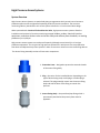
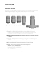
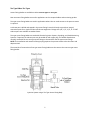
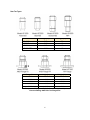
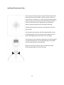
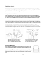
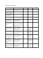
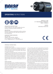
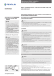
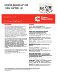
High Pressure
Access Systems
Operation Manual
Metal Samples Corrosion Monitoring Systems
A Division of Alabama Specialty Products, Inc.
152 Metal Samples Rd., Munford, AL 36268 Phone: (256) 358-4202 Fax: (256) 358-4515
E-mail: [email protected] Internet: www.metalsamples.com
Houston Office: 6327 Teal Mist Lane, Fulshear, TX 77441 Phone: (832) 451-6825
.
Table of Contents
System Overview ...................................................................................................................1
Safety Precautions .................................................................................................................2
Access Fitting Body Types ......................................................................................................3
Tee Type & Non-Tee Types ....................................................................................................5
Attaching the Access Fitting Body..........................................................................................8
Plug Assemblies......................................................................................................................10
Solid Plugs ..............................................................................................................................11
Hollow Plugs...........................................................................................................................12
Installing & Orienting the Plug ...............................................................................................13
Protective Covers ...................................................................................................................14
Cover Installation & Removal ................................................................................................16
.
High Pressure Access Systems
System Overview
High Pressure Access Systems are specialized piping arrangements which permit internal access to
production plant vessels and pipework operating under full process conditions. The corrosion
monitoring industry standard for such access systems is based on a 2-inch nominal bore design.
When operated with a Retrieval Tool and Service Valve, high pressure access systems allow the
installation and retrieval of corrosion monitoring coupon holders, probes, chemical injection
equipment, and other devices to be carried out safely and without plant shutdown, at working
pressures up to 3,600 psi.
High pressure access systems are used most frequently (although not exclusively) in oil and gas
production operations. This is typical of high pressure operations in which users are not prepared to
shut down and depressurize process systems in order to remove or install corrosion monitoring devices.
The Access Fitting Assembly consists of three main components:
1. Protective Cover – designed to protect the external threads
of the access fitting body.
2. Plug – the carrier for the installed device. Depending on the
type of device being used, a solid plug or a hollow plug is
selected. The plug assembly screws into the access fitting
body and seal the bore of the fitting to contain line
pressure.
3. Access Fitting Body – the specialized pipe fitting which is
permanently attached to the process plant vessel or
pipework.
1
Safety Precautions
1. Good engineering and operational practices should be adhered to at all times.
2. Do not use the retrieval tool unless you have familiarized yourself with its operation.
3. If this is the first time you have used the equipment or you are an infrequent user, you should review
the manual and, if possible, perform a trial operation on a mock fitting.
4. In addition to the requirements of this manual, all plant safety requirements and environmental
regulations must be followed.
2
Access Fitting Body
Access Fitting Body Types
High Pressure Access Fitting Bodies are available in styles that may be welded (Flareweld, Socketweld,
and Buttweld), threaded (NPT), or flanged (API, ANSI RF, ANSI RJ) to the pipe or vessel wall.
1. Flareweld – HP1000/HP1100 Flareweld bodies are the most widely used. These bodies
incorporate a reinforced welding neck and also have a radius machined into the base to
accommodate the curvature of the pipe or vessel to which the body is welded.
2. Buttweld – HP2000/HP2100 Buttweld access fittings are designed to be buttwelded directly to a
2” pipe end.
3. Socketweld – HP3000/HP3100 Socketweld fittings are designed to be welded directly to a 2”
socket end.
4. NPT – HP4000/HP4100 NPT fittings can be threaded into a 2” female NPT fitting.
5. Flanged – Flanged fittings are available in three standard configurations:
a.ANSI Ring Joint (RJ) – HP5000/HP5100
b.ANSI Raised Face (RF) – HP6000/HP6100
c.API – HP7000/HP7100
3
Access fittings are manufactured from materials which conform to NACE MR-0175 specifications for sour
service. Choice of material for the access fitting body is based on minimum operating temperature as
well as process stream corrosivity. "Standard" temperature materials are suitable for use above a
minimum operating temperature of -20°F (-29°C). "Low Temperature" materials should be selected for
minimum operating temperatures below this value.
The Metal Samples Corrosion Monitoring Systems standard material specification for Flareweld
Socketweld, Buttweld, and NPT bodies is AISI 1018 for standard temperature and ASTM A350LF2 for low
temperature. For flanged fittings, ASTM A105 is used for standard temperature and ASTM A350LF2 for
low temperature. However, all access fitting components can be made to order in any customerspecified material; carbon or stainless steel, duplex materials, or other more exotic alloys.
All access fitting bodies have an external 3-inch ACME thread, which is used to attach the service valve
during retrieval operations. Access fitting bodies should always be fitted with a cover which is designed
to protect both external thread and also the service valve sealing surfaces.
4
Tee Type & Non-Tee Types
Access Fitting Bodies are available as either non-tee types or tee types.
Non-tee access fitting bodies are used in applications such as coupon holders and monitoring probes.
Tee type access fitting bodies are used in applications where inlet or outlet access to the process stream
is required.
A side-tee port is drilled and tapped in the access fitting’s extra thick body to provide an integral
connection point for a nipple and shut-off valve arrangement. Fittings with 1/4", 1/2", 3/4", or 1" FNPT
side-tee ports are available as standard items.
Tee type access fitting bodies are used with Chemical Injection Systems, Sampling, and Sand Monitoring
Systems. If required, the side-tee port may be sealed off with a pipe plug. This would allow devices
normally used with the non-tee type access fittings to be used with the tee type access fittings.
NOTE: The installation and removal of the pipe plug requires the process stream to be shut down and
depressurized.
The materials of construction of tee type access fitting bodies are the same as the non-tee type access
fitting bodies.
Injection System using a Tee Type Access Fitting Body
5
Non-Tee Types
Model
Height (in )
Weight (lbs)
HP1 000 Fla reweld
HP2000 Buttwe ld
HP3000 Socketweld
HP4000 NPT
5.25
5.25
6.25
6.25
5.5
4.5
4.5
4.5
Flange Size
Height (in )
Weight (lbs)
150#
5.25
10.50
300#
5.25
11.50
4/600#
6.25
15.25
9/1500#
6.25
30.75
2500#
6.25
40.00
Temperature Rating: -20° F (28.9° C) to +350° F (176.6° C)
Pressure Rating: 6000 PSI or as Flange Size
6
Tee Types
1/4" T
1/2" T
3/4" T
1" T
Weight Weight Height Weight Height Weight Height Weight
(in)
(lbs)
(in)
(lbs)
(in)
(lbs)
(in)
(lbs)
5.25
4.5
6.25
5.75
6.25
6.5
7.25
7
Model
H P5100
ANSI
Flange RJ
Flange
Size
150#
300#
4/600#
1 /4 " T
1 /2 " T
Height Weight Height Weight
(in)
(lbs)
(in)
(lbs)
5.25 9.50
7.25
10.00
5.25 11.50
7.25
11.75
6.25
12.75
7.25
13.00
3/4 " T
Height Weight Height Weight
(in)
(lbs)
(in)
(lbs)
7.25
10.00
7.25 10.50
7.25
12.00
7.25
12.00
7.25
13.00
9/1500#
6.25 25.75
8.25 26.00
8.25
26.25
2500#
6.25 40.20
8.25 40.50
8.25
40.40
150#
5.25 9.75
7.25
10.00
7.25
13.00
H P6100
300#
5.25 11.50
7.25
11.75
7.25
17.00
ANSI
4/600#
6.25 12.75
7.25
13.00
7.25
18.00
Flange RF 9/1500#
6.25 25.75
8.25 26.00
8.25
38.00
2500#
6.25 40.10
8.25 40.50
8.25
45.50
H P7100
2000#
6.25 15.75
7.25
18.00
7.25
18.00
API
3/5000#
6.25 31.00
8.25 38.00
8.25
38.00
Flange
10000#
6.25 40.50
8.25 45 .50
8.25
45.50
Temperature Rating: -20° F (28.9° C) to +350° F (176.6° C)
Pressure Rating: 6000 PSI or as Flange Size
7
1"T
7.25
13 .00
8.25
8.25
7.25
7.25
7.25
8.25
8.25
7.25
26.50
40.75
13.00
17.00
18.00
38.00
45.50
18.00
8.25
38.00
8.25
45.50
Attaching the Access Fitting Body
Access Fitting Bodies which have a welded end connection (flareweld, buttweld, or socketweld), must
be welded according to local and plant codes.
NPT type access fittings are manufactured in accordance with ANSI/ASME B1.20.1 -Specification for
Taper Pipe Threads. This fitting should be installed by a qualified technician using standard protocol for
taper pipe threads.
ANSI flange fittings are manufactured in accordance with ANSI B16.5 – Specification for Flanges and
Flanged Fittings. Flange gaskets and stud-and-nut sets are not provided with the access fitting body.
This fitting should be installed by a qualified technician using standard protocol for flange installation.
General Welding Instructions
1. Determine if the system in which the access fitting is to be placed will permit welding.
2. Remove the plug assembly from access fitting prior to welding.
3. Protect the internal and external threads from weld splatter with a temperature resistant cloth
wrapped around the body and dampened on the outside only.
4. Place the access fitting on the line and align.
5. Establish proper weld gap by placing 1/16" spacer rods under the access fitting.
6. Most steels should be preheated prior to welding when the fluid or metal temperature is less than
50°F.
7. Arc welding should be used to minimize warping.
8. Preheat access fitting body to 400°F and tack weld, using AWS 1/8" welding rod of the proper grade.
9. Remove weld gap spacers. Remove tack weld slag.
10. Tie the root pass into the tack weld to make complete fusion. Apply a stringer bead around the base
of the fitting, removing slag at each pass.
11. Tempil sticks should be used to insure that the access fitting body temperature does not exceed
1000°F.
8
12. Apply continuous cover beads to fill the bevel.
13. Apply a post heat of 600°F for fifteen (15) minutes. Wrap with insulating cloth and allow to cool.
14. Hot tapping will be necessary for lines in service.
Note: Weld time approximately one (1) hour with welder and helper.
The procedure described above is for general access fitting installation reference. Metal Samples
Corrosion Monitoring Systems shall not be held responsible or liable in any way for loss or damage
resulting therefrom, or any regulations which they may conflict.
9
Plug Assemblies
The Plug Assembly is the retrievable carrier which holds corrosion monitoring, chemical injection, or
various other devices which may be installed through the access fitting. There are two distinct types of
plug assemblies - the Solid Plug and the Hollow Plug.
The plug assembly screws into the bore of the access fitting body and is designed to seal the fitting
against line pressure. When tee type access fittings are being used, a pipe plug or nipple and shut-off
valve is additionally required to seal the fitting.
The standard material of construction for the plug assembly is 316 Stainless Steel. It should be noted
that when stainless steel or duplex materials are specified for the access fitting body, the plug assembly
should be specified to be Nitronic 60 to prevent thread galling.
All plug assemblies are individually pressure tested at the factory and are rated for operation at 3600
psi. The operating temperature range for standard plug assemblies is -50°F (-45°C) to 350°F (176°C), but
this range can be extended by use of alternative sealing materials.
10
Solid Plugs
Solid plugs carry coupon holders, injection/sampling systems, sand probes, and bioprobes
The solid plug nut is unscrewed from the base of the plug and replaced by the device being installed. A
left-hand thread is used to ensure that installed devices do not become loose during the retrieval
procedure.
Pipe Plug – Protects internal threads and provides secondary backup
seal. Must be removed during retrieval operations.
Solid Plug Body
O-Ring Seal
Primary Packing Seal
Solid Plug Nut – Only used when no other device is attached.
Part No.
Material
Pipe Plug
Solid Plug Body
Description
HA700697158
HA700006158
316SS
316 SS
O-Ring
HA700600834
Viton
Primary Packing
HA700266785
PTFE (25% G)
Solid Plug Nut
HA7002101 58
316 SS
09158E1032ST0187
316SS
SetScrew
11
®
Hollow Plugs
Hollow plugs are used with electrical resistance probes, linear polarization resistance probes, and
hydrogen probes.
To connect these devices, the hollow plug seal nut is removed and the monitoring device is screwed into
the female thread in the base of the hollow plug. A left-hand thread is used. Access is allowed through
the top of the hollow plug for electrical connections to be made directly to probes for the purpose of
taking readings.
Thread Protector – Must be removed during retrieval operations.
Hollow Plug Body.
Primary Packing Seal.
Hollow Plug Nut.
Device Seal.
Bore Seal Nut – Only used when no other device is attached.
Description
Pipe Plug
Part No.
HA700167
HA700300158
HA700266785
HA700302158
09158E1032ST0187
HA700277785
HA700311158
Hollow Plug Body Anti-Gall Coating
Primary Packing
Hollow Plug Nut
Set Screws (2)
Probe Packing
Hollow Plug Bore Sealing Nut
12
Material
Plastic
316 SS
PTFE (25% G)
316 SS
316 SS
PTFE (25% G)
316 SS
Installing & Orienting the Plug
If the corrosion monitoring device requires radial orientation with
the product flow (coupon holder, LP probe, injection quill, etc.),
you will need to “reference” or “index” the plug assembly by filing
a notch across the top of the hex (see left). The notch should be
filed so that the device can be aligned with the product flow.
Apply an appropriate grease to the full length of the plug.
If inserting the plug under pressure, use the Retriever Tool and
Service Valve.
If inserting the plug manually, thread the plug assembly into the
access fitting body. Do not use excessive force and be sure that
the threads engage properly to prevent cross-threading.
The reference mark as previously mentioned must now be aligned
to product flow direction. Turn the plug assembly hex clockwise
until the mark aligns to the flow direction.
Make sure the fitting is clean and dry, and install the thread
protecting pipe plug into the top of the plug.
13
Protective Covers
Protective covers are designed with internal threads which mate with the access fitting body and are
recommended to prevent damage to the fitting’s exterior thread. In addition, they protect the surfaces
against which the service valve seals during retrieval operations.
Heavy Duty Pressure Rated Covers
Heavy duty pressure rated covers are manufactured as standard in AISI 1018 and are supplied with a
paint coat finish suitable for the most aggressive environments. Covers are individually pressure tested
for a pressure rating of 4000 psi and are available with an optional bleed valve and/or pressure gauge.
Covers are available with or without a center hole. Center holes are required when an external sensor
connection is required to be permanently installed. Covers with an unthreaded 1 3/8" (3.5 cm) diameter
center hole are required for installations where mechanical Hydrogen Probes are installed. Covers with a
1/2" NPT center hole are required where continuous monitoring of electrical probes is required.
Connection of an electrical probe to a permanent monitoring instrument requires the use of a probe
adapter that extends through the 1/2" hole in the cover. The probe adaptor must be ordered separately.
Heavy duty pressure rated cover with ½”
NPT center hole and with 2 ea. ¼” NPT
holes for needle valve and pressure gauge
Heavy duty pressure rated cover without
center hole and with 2 ea. ¼” NPT holes
for needle valve and pressure gauge
Non-Pressure Rated Covers
More economical than heavy duty pressure rated covers, non-pressure rated
covers are internally threaded to protect against mechanical damage to the
external access fitting threads. Non-pressure rated covers are available in
plastic or metal, with the plastic version having the added advantage of being
lightweight and non-sparking. They can be ordered with or without a center
hole.
14
Protective Covers – Part Numbers
Description
Application
Part No.
Material
Weight
Non-Pressure Rated
Cover without Hole
Intermittent Monitoring Chemical Injection
HA700734413
Carbon Steel
2.5 lbs. (1.6 kg)
N o n - P r e s su r e Rat ed
Cover w/ 1/2" NPT Hole
Continuous Monitoring
HA700732413
Carbon Steel
2.0 lbs. (0.9 kg)
Non-Pressure Rated
Cover without Hole
Intermittent Monitoring
HA700436709
Nylon
0.5 lbs. (0.2 kg)
N o n - P r e s su r e Rat ed
Cover w/ 1/2" NPT Hole
Continuous Monitoring
HA700435709
Nylon
0.5 lbs. (0.2 kg)
Heavy Duty Pressure
Rated Cover w/o Hole
Intermittent Monitoring
(rated for 6,000 PSI)
HA700735413
Carbon Steel
9 lbs. (4.1 kg)
Heavy Duty Pressure
Rated Cover with 1/2"
NPT Hole
Continuous Monitoring provides a secondary seal
and allows for probe adapter
(rated for 6,000 PSI)
HA700731413
Carbon Steel
9 lbs. (4.1 kg)
Heavy Duty Pressure
Rated Cover and Bleed
Valve
Continuous Monitoring provides a secondary seal
(rated for 6,000 PSI)
HA700480413
CS (cover),
316 SS
(bleed val.)
9 lbs. (4.1 kg)
Hea vy Dut y P re s su re
Rat ed Co v er , B l ee d
Valve & Pressure Gauge
Continuous Monitoring provides a secondary seal
(rated for 6,000 PSI)
HA700481413
CS (cover),
316 SS (bleed
val. & gauge)
10 lbs. (4.5 kg)
Heavy Duty Pressure
Rat ed Co v er , B l ee d
Valve, Pressure Gauge
and 1/2" NPT Hole
Continuous Monitoring provides a secondary seal
(rated for 6,000 PSI)
HA700482413
CS (cover),
316 SS (bleed
val. & gauge)
9 lbs. (4.1 kg)
Hea vy Dut y
Pr e ssur e Rated Cover
w/ Bleed Valve & 1/2"
NPT Hole
Continuous Monitoring provides a secondary seal
(rated for 6,000 PSI)
HA700483413
CS (cover),
316 SS (bleed
val.)
9 lbs. (4.1 kg)
Hea vy Dut y P re s su re
Rated Cover w/ Pressure
Gauge & 1/2" NPT Hole
Continuous Monitoring provides a secondary seal
(rated for 6,000 PSI)
HA700484413
CS (cover),
316 SS
(gauge)
9 lbs. (4.1 kg)
15
Cover Installation & Removal
All pressure retaining covers are supplied with an internal o-ring. Ensure that the o-ring is installed into
the internal groove. Ensure the external threads on the access fitting body are clean and dry. Lubricate
the threads with an appropriate grease, and thread the cover onto the fitting. Non-pressure retaining
covers can be installed hand-tight. Pressure retaining covers should be tightened with a spanner
wrench. To remove the cover, unscrew the cover from the fitting, using a spanner wrench to loosen the
cover, if required. If pressure retaining covers are used, be sure all pressure is bled from the cover
before removal. If it is not possible to bleed pressure, the cover should not be removed until the line is
depressurized.
16