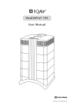
1
TM
CleanZone H13
CleanZone 230/50 Neutral 3302
Clean Air Hood / Particle Extraction Hood
(Dual-Function Filtration System)
Instruction Manual
Swiss Made
Contents
INTRODUCTION
Important Safety Instructions
Disclaimer
Summary of the Key Features
Page
3
3
4
ASSEMBLING THE CLEANZONE
1. 1
Unpacking the CleanZone
1. 2
Description of the Components
1. 3
Selecting the Required Setup
1. 4
Securing the CleanZone to the Hood
1. 5
Fitting the Control Panel
5
5
6
7
8
USING THE CONTROL PANEL
2. 1
Description of Control Panel Elements
2. 2
Fan Speed and Air Delivery
2. 3
Using the Menu Functions
2. 4
Programming the Timer Functions
2. 5
Programming the Filter Load Index
2. 6
The Filter Life Menu
2. 7
Resetting the Filter Life LED
2. 8
Setting the Display Language
9
11
12
14
18
21
22
23
REPLACING FILTERS
3. 1
Location of the Filter Elements
3. 2
Ordering Replacement Filters
3. 3
Replacing the Pre-Filter
3. 4
Replacing the HEPA Filter
24
25
25
27
CARING FOR YOUR CLEANZONE
4. 1
Cleaning the Housing
4. 2
Monitoring Filter Replacement
4. 3
Maintenance-Free Fan
29
29
29
IMPORTANT INFORMATION & TECHNICAL SPECIFICATIONS
5. 1
Using the CleanZone in Critical Environments
5. 2
Technical Specifications
5. 3
EC Declaration of Conformity
30
31
32
WARRANTY & SERVICE INFORMATION
6. 1
Technical Support
6. 2
How to Register your CleanZone
6. 3
Warranty Conditions
33
33
34
The IQAir Group reserves the right to change specifications contained in this document at any time and without prior notice.
© 2002 IQAir Group. All rights reserved. IQAir and HyperHEPA are the registered trademarks of the IQAir Group. CleanZone and PreMax are trademarks of the IQAir
Group. CleanZone filters are protected under U.S. patents 6 001145 and 6 159 260.
Other U.S., European and Asian patents pending.
Introduction
Congratulations on the purchase of the CleanZone high-performance air filtration system. This
system will provide you with many years of exceptional air cleaning performance. For your
safety please study this manual carefully. Knowing about the CleanZone’s functions and
features will also enable you to achieve the best results with the system. Keep this manual for
future reference.
Important Safety Instructions
•
•
•
•
•
•
•
•
•
•
•
•
Read these instructions before using the appliance.
Do not immerse the system in water or other liquids.
Always disconnect the system from power before servicing, opening or cleaning.
Do not operate the system if it has a damaged cord or plug, if the motor fan
fails to rotate, if it is not working properly, if it has been dropped or damaged, or come into
contact with water. Contact your point of purchase for service or repair.
Only use this appliance for its intented purpose.
Do not use this appliance in areas with very high concentrations of dust or powder to prevent
the danger of dust explosions.
Do not use this appliance near explosives.
Do not use accessories or filters not recommended by the manufacturer.
Do not use outdoors.
Do not obstruct the air inlet and air outlet of the system.
Only use this appliance in an upright position.
Keep the power cord away from heated surfaces.
Disclaimer
While this CleanZone air cleaning system has been individually tested and certified at the production
stage, the manufacturer recommends that the system is re-tested and certified before use for critical
applications. This will help to ensure the proper functioning of all component parts after transport
and installation.
Although CleanZone systems may be advertised and sold to be suitable for the use in specific
environments and to deal with specific contaminants, the manufacturer and distributors make no
claim as to the specific air cleaning results that are achieved under the user’s individual operating
conditions. The filtration efficiencies that can be realised with this air filtration system (as with any air
filtration system) will depend to a significant degree on circumstantial factors which are out of
control of the manufacturer and distributors. Important factors which will influence air filtration
results include:
-
the type of air pollutants present and their concentration,
the intensity of the pollutant source(s),
the operating speed of the system,
the temperature and humidity and
the saturation state of the filters in the system.
Consult a qualified specialist to determine an effective and comprehensive contamination control
strategy.
3
Introduction
Summary of Key Features
State-of-the-art filtration technology
Your CleanZone H13 air filtration system utilises advanced air filtration technology to remove
solid and liquid contaminants such as dust, aerosols, bacteria, viruses and smoke particles.
The CleanZone H13 features the following air filtration technologies:
• High-capacity pre-filtration for coarse and fine dust particles
• Cleanroom grade HEPA (high-efficiency particulate air) filtration for ultra-fine particles
Advanced control panel features
To provide you with important information about your air cleaner’s performance and to allow you
to take advantage of advanced operational features, your CleanZone is equipped with a state-ofthe-art control panel with a 2x16 character LCD display. The unique features include:
• A display that informs you about the air flow rate at different fan speed settings
• Electronic controls that monitor the remaining life of the system’s individual filter elements
and prompt filter replacement
• A daily and weekly timer to automatically switch the CleanZone on and off at a preset time
• A countdown timer to allow the CleanZone to run for a set number of hours before
automatic switch-off
Easy filter replacement
To ensure convenient filter replacement, your CleanZone features a revolutionary housing
design. By releasing the latches on the front and back of the system, immediate access is gained
to the filter elements. This enables the quick and simple replacement of the filters without tools.
Environmentally friendly design
The CleanZone’s filter elements have been designed to ensure maximum performance, while
creating minimum waste. This is achieved by employing light-weight framing and large surface
long life filter media.
Low energy consumption
Due to a high-performance centrifugal fan system, the CleanZone consumes little energy in
relation to the amount of filtered air it produces. Unlike many other air cleaners, the energy
consumption of the CleanZone decreases proportionally when set on lower fan speeds, thanks to
a special electrical speed control set-up.
4
Chapter 1
Assembling the CleanZone
1.1 Unpacking the CleanZone
Your CleanZone is supplied in 2 boxes. The smaller box contains the air filtration system with its
accessories and the larger box contains the acrylic hood. To unpack your CleanZone, remove the
small box containing the power cord and the control panel. Then remove the square styrofoam
pad and carefully lift the system out of the box. Remove the plastic bag and foam belt.
To unpack the acrylic hood, open the top of the larger box and remove the inner box. Open the
inner box and carefully lift the hood out. Remove the plastic bag.
Keep the packaging for future transport and service needs.
1.2 Description of the components
CleanZone
air filtration system
Power cord
Acrylic hood
Instruction manual
Control panel
touchpad, housing
and screws
5
Certificate of performance
Chapter 1 - Assembling the CleanZone
1.3 Selecting the Required Setup
IMPORTANT NOTE: The CleanZone H13 is a dual-function filtration system and can be
used in two different ways. Carefully select the appropriate function for your application.
Fitting the System the wrong way may result in pollution exposure.
A) Particle Extraction Hood
If the CleanZone is set up with the arrows on front label pointing up, dirty air from the hood is
drawn into the system, filtered and released to the room air.
2
1
1
Dirty air from the acrylic hood is drawn into the CleanZone. A large-surface pre-filter
removes coarse and fine pollution particles.
2
In the second filtration stage, the CleanZone’s tightly pleated HEPA filter removes even
sub-micron particulates before the air is released to the room air.
or
B) Clean Air Hood
If the CleanZone is set up with the arrows on front label pointing down, dirty room air is drawn
into the system, filtered and released into the hood.
1
2
1
Dirty room air is drawn into the CleanZone. A large-surface pre-filter removes coarse and
fine pollution particles.
2
In the second filtration stage, the CleanZone’s tightly pleated HEPA filter removes even
sub-micron particulates before the air is released into the acrylic hood.
6
Chapter 1 - Assembling the CleanZone
1.4 Securing the CleanZone to the Hood
IMPORTANT NOTE:
Carefully select which way around the CleanZone is to be used for your application
purposes. Fitting the system the wrong way may result in pollution exposure.
Once the appropriate setup has been selected, the CleanZone can be fitted to the acrylic hood.
Decide on a suitable location and place the hood onto the surface where the CleanZone system
is to be used.
1) Lift the CleanZone system on top of the
acrylic hood and place it carefully within the
placement tabs at the top edge of the hood.
2) Screw the supplied wing screws through
the pre-drilled holes on both sides of the
hood into the metal frame.
3) The CleanZone is now securely fixed to the
hood. Note: To relocate the CleanZone, it is
adviseable to remove the system from the
hood.
7
Chapter 1 - Assembling your CleanZone
1.5 Fitting the Control Panel
Once the CleanZone has been secured to the hood, the control panel can be fitted.
1) Take the flat-band cable on the front of the
system and slide it trough the gap of the
control panel housing.
2) Ensure that the curved edge of the panel
housing faces down. Secure the housing with
the supplied wing screws.
3) Plug the red clip attached to the flat-band
cable into the red socked on the side of the
touchpad.
4) Ensure that the cable is securely attached.
5) Snap the touchpad onto the control panel
housing.
6) You can now connect the CleanZone to
mains power with the supplied power cable.
8
Chapter 2
Using the Control Panel
Your CleanZone is operated and controlled via the electronic control panel which is located on
top of the front locking arm.
The electronic control panel allows you to:
- control the fan speed and corresponding air delivery rate
- check the remaining filter life of the individual filters
- set the daily, weekly and countdown timers
- reset the filter life counter after replacing a filter
2.1 Description of Control Panel Elements
™
CleanZone
Filter Life Monitor
Liquid crystal
display (LCD)
F
4
F
3
LED= Light Emitting
Diode
Filter Life LED:
Filter 4 (HEPA Filter)
Fan Speed LEDs
▲
Timer LED
MENU
ENTER
F
2
F
1
Filter Life LED:
Filter 1 (Pre-Filter)
High-Performance Air Filtration Module
Swiss Made
Power
Key
Arrow
Key
Menu
Key
Enter
Key
Note: Filter positions 2+3 are
not allocated in this model
LCD Display
The 2-line LCD displays important information about the
system’s operational status.
On standby, the first line shows the current day and time. If the
timer is turned on, the set start and stop times will be displayed
on the second line.
If the system is on, the first line displays the current speed
setting and the second line displays the corresponding air
delivery rate of the unit.
By pressing the Menu key, eight different menu functions may
be accessed.
9
Main window: standby mode
Main window: running mode
Filter Life Menu Window
Chapter 2 - Using the Control Panel
Power Key
The Power key turns your system on and off. When your CleanZone is turned off, the fan stops to
run, but the system will remain connected to the power supply (standby mode). The standby
mode allows for automatic timer start-up. In the standby mode, you can also access the different
menu functions.
Arrow Key
When the air cleaner is switched on, the ▲ key allows you to adjust the fan speed. In the enter
mode, indicated by the appearance of a black flashing cursor (see “Enter Key” below), you may
also use the ▲ key to modify the selected setting in the display window.
▲
Menu Key
The Menu key allows you to access any one of eight menus. Press the Menu key once to reach the
first menu function. Press the Menu key twice to reach the second menu function, and so on.
Menu
Enter Key
The Enter key, if pressed for 3 seconds, allows you to modify a setting.The enter mode is indicated
by a flashing cursor on the modifiable setting. Pressing the Enter key again will save any entry
and move the cursor to the next modifiable item in the display window.When the last modifiable
choice in a window is confirmed with the Enter key, the enter mode is automatically terminated.
Enter
Locking Function
The control panel can be locked to avoid tempering with the control settings. To lock or unlock
the control panel, the Menu and the Enter key have to be pressed down simultaneously for 3
seconds. The activated locking function is indicated with a star symbol in the control panel
display. The locking function is also cancelled by disrupting the power supply.
Menu
Enter
Filter Life LEDs
Whenever the air cleaner is running, the colour of the filter life LEDs (light emitting diodes)
indicates the state of the individual filters in the unit.
The filter life indicator LEDs signal four possible stages in the life of the filter:
Green:
The filter is still within 80% of its estimated life span.
Orange:
The filter is approaching the last 20% of its estimated life span.
Red:
The filter has reached the end of its estimated life span.
Red blinking: The filter has passed its estimated life span and should be replaced immediately.
The air cleaner’s effectiveness is likely to have been reduced dramatically, either
due to a reduction in air flow (particle filters are clogged) or a reduction in filter
efficiency (carbon filter is saturated).
Fan Speed LEDs
These LEDs simulate the fan speed through the frequency of their rotation.The faster the rotation
of the fan speed LEDs, the faster the actual fan speed of the unit.
10
Chapter 2 - Using the Control Panel
2.2 Fan Speed and Air Delivery
Your CleanZone can be set to run at five fan speeds which correspond to five different air flow
rates. Speed 1 is the lowest, speed 5 the highest fan speed.The higher the air flow, the more room
air will be filtered by the unit.
To allow better evaluation of the performance of your air cleaner at different fan speeds, the
standard display window shows in addition to the fan speed also the air delivery rate (air flow).
The displayed air flow is factory preset and is not measured by the air cleaner itself.
Regulating Fan Speed
1. When the CleanZone is turned off (standby
mode), the first line of the LCD display shows the
current day and time. To switch the unit on, press the
Power key on the far left of the control panel.
2. The LCD now displays the fan speed and the
corresponding air flow rate. Note: the system
starts at the fan speed at which it was running
when it was last used.
3. To change the fan speed, press the ▲ key.
Pressing the ▲ key repeatedly will increase the
fan speed until the maximum fan speed is reached,
then starting off at the lowest speed again.
N.B. The air delivery readings (air flow)
displayed in this manual are examples only
and will vary according to model.
Changing the Air Volume Units
1. You can change the air volume units which are displayed from metric to imperial, i.e. from cubic meters
per hour (m2/h) to cubic feet per minute (cfm), and
vice versa, by pressing the Enter key for three
seconds either when the unit is turned on or off.
2. When the first character of the air volume units
starts to flash, press the ▲ key to change the units.
3. Press the Enter key to confirm the air volume unit
change. Until modified again, the air flow rate will
now be displayed in the newly selected units.
11
Chapter 2 - Using the Control Panel
2.3 Using the Menu Functions
Your CleanZone’s control panel lets you choose from a number of menu options which allow you
to take advantage of the additional features.There are eight menu windows that can be accessed
with the Menu key.
Press the Menu key once to reach the first menu window. Press the Menu key twice to reach the
second menu window, and so on.The menus can be accessed both in standby and running mode.
Menu Overview
Pressing the Menu key accesses the menus in the following order:
1. Time & Day Menu
Allows you to view and change the current time
and day setting.
2. Daily Timer Menu
Allows you to view and enter a start and stop time at
which the unit will automatically switch on and off.
It also allows you to activate/deactivate the timer
without changing the start and stop times.
3. Weekly Timer Menu
Allows you to set the daily timer for certain days
of the week.
4. Countdown Timer Menu
Allows you to program the unit to run for a fixed
period (1-72 hours) before switching off
automatically.
5. Filter Load Index Menu
Allows you to view and modify the air pollution
index, which allows the unit to calculate the air
pollution load in the filter elements and the resulting
filter life.
12
Chapter 2 - Using the Control Panel
6. Filter Life Menu
Allows you to view the remaining filter life of the
individual filter elements.
7. New Filter Menu
Allows you to reset the remaining filter life after
changing a filter element.
8. Display Language Menu
Allows you to change the display language.
Description of Key Functions in Relation to Menus
Menu Key
The Menu key allows you to access one of eight
menus. Press the Menu key once to reach the first
menu window. Press the Menu key twice to reach
the second menu window, and so on. If no key is
pressed for eight seconds in a menu window, the
display will revert to the main display window.
Power
Key
▲
Menu
Enter
Arrow
Key
Menu
Key
Enter
Key
Note: If you are in a menu window and would like to
remain in the window for more than eight seconds,
keep pressing the ▲ key.
Enter Key
When you are in a menu window, the Enter key, if pressed for three seconds, allows you to modify
a menu setting.The enter mode is signalised by a flashing cursor in the display. Pressing the Enter
key again will save the entry and move the flashing cursor to the next modifiable item in the
menu window. When the last modifiable choice in a menu has been confirmed with the Enter
key, the enter mode is automatically terminated. The LCD will then display the current menu
settings for another eight seconds before returning to the main window display.
Power Key
When you are in a menu window, the Power key serves as a quick exit key to return to the main
display window.
Arrow Key
When you are in the enter mode (cursor flashing) in a menu window, the ▲ key allows you to
modify the flashing item.
13
Chapter 2 - Using the Control Panel
2.4 Programming the Timer Functions
Daily Timer Menu
The Daily Timer Menu allows you to set one start and one stop time at which the system will
automatically switch itself on and off.The CleanZone will start up in the fan speed it was in, when
it was last used. The timer status field indicates whether the timer is enabled or disabled. The
timer status field allows you to quickly enable/disable the daily timer without erasing the set start
and stop times. The Weekly Timer Menu lets you disable the timer on certain days of the week.
timer status field
1. To reach the Daily Timer Menu from the main
display window, press the Menu key twice.
start time
2. Press the Enter key until the cursor starts to flash.
3. Press the ▲ key once to enable the timer.
Note: If the start time and the stop time are
identical, the timer cannot be enabled.
4. Press the Enter key to save the timer status setting
and to proceed to the start time.
5. Set the desired start hour by pressing the ▲ key.
6. Press the Enter key to save the start hour and
to proceed to the minute setting.
7. Enter the desired start minute setting by pressing
the ▲ key. Note: The minute settings can only be
set in five minute increments.
8. Press the Enter key to save the start time and to
proceed to the stop time setting.
14
stop time
Chapter 2 - Using the Control Panel
9. Enter the desired stop hour by pressing the ▲ key.
10. Press the Enter key to save the stop hour and
to proceed to the minute setting.
11. Enter the desired minute setting by pressing
the ▲ key.
12. Press the Enter key to save the minute setting
and to exit the enter mode.
Weekly Timer Menu
The weekly timer allows you to deactivate the daily timer on certain days of the week. In its
default setting the daily timer is enabled on all seven days of the week. This is indicated by stars
below the abbreviations of the days.
Note: At least one day of the week must be enabled with a star to be able to run the daily timer
(auto timer). If the timer is disabled on all days of the week, the timer status field in the Daily Timer
Menu will switch to “OFF” and the timer will be disabled.
1. To reach the Weekly Timer Menu from the main
window, press the Menu key three times.
2. Press and hold down the Enter key until the cursor
appears.
3. Press the ▲ key to activate (star) or deactivate (no
star) the daily time on a particular day. Press the
Enter key to proceed to the next day.
4. Repeat the same procedure until the timer has been
enabled/disabled on the desired days. The final Enter
command exits you from the enter mode.
15
Chapter 2 - Using the Control Panel
Timer Information in the Control Panel
The CleanZone’s control panel keeps you informed about the timer status without the need to
use the Daily & Weekly Timer Menus. When the timer is enabled, the second line of the display’s
main window shows the timer’s current start and the stop times. In addition, the timer LED
indicates with a green light whether the timer is enabled.
Display’s Main Window
1. - Timer is disabled
- Unit is turned off (standby)
2. - Timer is disabled
- Unit is running
Timer LED
Timer Disabled
When the timer is disabled (default
setting), no timer information will be
displayed in the main window.
red
When the unit is turned off (1), the
timer status LED is red.
When the unit is running (2), the timer
status LED will turn off.
off
Timer Enabled
3. - Timer is enabled
- Unit is turned off (standby)
green
4. - Timer is enabled
- Unit is running
green
5. - Timer is enabled
- Unit is running
green
6. - Timer is enabled
- Unit was turned on outside
normal timer period
green
16
When the timer is enabled, the second
line of the display shows the day and
the time when the unit will next switch
on (3) or when it actually switched on
(4). This is followed by the time when
the system will switch off.
If the start time is before 00:00 hours
and the stop time after 00:00 hours, i.e.
the stop time is on the next day, the day
is displayed in front of the start and the
stop times (5).
If the system is switched on manually
outside the timer period, it will run until
the next programmed stop time. The
second line of the main display window
will show only the time when the
system will switch off automatically (6).
Chapter 2 - Using the Control Panel
Countdown Timer Menu
The Countdown Timer Menu allows you to set a period from 1 to 72 hours for which the
CleanZone will run and then switch off automatically.
Note: Should the daily timer also be enabled, the countdown timer will take priority until the
countdown period has elapsed.
1. To reach the Countdown Timer Menu from the main
display window, press the Menu key four times.
2. Press down the Enter key until the black cursor
appears.
3. Press the ▲ key to enter the desired countdown
period (1 to 72 hours).
4. Press the Enter key to confirm the chosen
countdown period and to exit the enter mode.
5. The remaining countdown time now appears on the
second line of the main display window.
Note:
The countdown timer can be cancelled at any time by
switching the system off with the Power key.
17
Chapter 2 - Using the Control Panel
Chapter 2 Understanding the Control Panel
2. 5 Programming the Filter Load Index
The filter load indexes serve as information input to the filter life monitor about the room air
pollution and the resulting pollution load on the unit’s different filter elements. The filter load
indexes are used by the filter life monitor for a more accurate calculation of the remaining filter
life.
The Filter Load Index Menu allows you to view and modify two filter load indexes. The two
indexes are based on air pollutant groups that have particular impact on the life of the filters.
Large Dust Index
Fine Dust Index
LARGE DUST INDEX: This index is based on the group of coarse or heavy dust. This dust can
contain fibers with several millimeters in length down to particles a mere 0.003 mm in size. This
type of dust will generally settle within an hour after generation or agitation on top of surfaces.
It consists of fibers, pollen, spores, dander, wood dust, etc.
FINE DUST INDEX: This index is based on the group of fine dust particles. This type of dust is
smaller than 0.003 mm (3 µm) in size and will remain airborne for longer periods of time.This dust
group is made up of small combustion particles as well as allergens, tobacco smoke particles and
microorganisms.
Determining and Modifying the Filter Load Index
The setting for each of the three filter load indexes can range from 1 and 9. Index setting 1
corresponds to the lowest, and 9 to the highest anticipated filter load.Your CleanZone is supplied
with the following default filter load index settings.:
Large Dust Index:
Fine Dust Index:
4
4
There are a number of factors that may make a modification of the default index settings
necessary in order to ensure the most accurate filter life display possible.
18
Chapter 2 - Using the Control Panel
Dusty Environments
Environments with a high dust content may shorten the life of the pre-filter. If there is a frequently
high dust content in your environment, add the following values to your index setting:
Dust Presence
Large Dust Index Fine Dust Index
Above average
+2
+1
High
+3
+2
Very high
+4
+3
Limitations of Filter Load Indexes
The concept of filter load indexes allows for a more precise calculation of the remaining filter life
than with regular filter life counters. Yet, the determination of filter load indexes underlies in its
definition some natural limitations. This is why it is important, especially if there is a noticable
decrease in filter performance, to change filters ahead of the indicated filter life. In such a case, it
may be necessary to adjust the appropriate filter load settings to a higher value.
We continuously collect laboratory and field information to make the regulation of the filter load
indexes even more accurate and simple. From time to time we may update our registered
customers with additional information in this regard.
19
Chapter 2 - Using the Control Panel
Modifying the Filter Load Indexes
The Filter Load Index Menu lets you adjust indexes to reflect more closely the situation in your
particular application environment.
1. Press the Menu key five times to reach the Filter
Load Index Menu.
2. Press and hold down the Enter key until the
cursor appears.
3. Press the ▲ key to modify the large dust index.
4. Press the Enter key to save the large dust index
setting and proceed to the fine dust index.
5. Press the ▲ key to modify the fine dust index.
6. Press the Enter key to save the fine dust index
setting.
20
Chapter 2 - Using the Control Panel
2.6 The Filter Life Menu
Your CleanZone is equipped with an electronic filter life monitor that calculates the remaining life
of the system’s filter elements. Thanks to the filter life monitor, you do not have to guess when
filters need to be replaced or replace them at fixed intervals (which seldomly correspond to the
actual amount of use). The filter life monitor keeps track of the most important factors affecting
the life of your filter elements.The Filter Life Menu displays at any given time the remaining life of
the individual filter elements as calculated by the filter life monitor.
1. To reach the Filter Life Menu from the main display
window, press the Menu key six times. The remaining
life of filter 1 will appear.
2. Press the ▲ key to view the remaining life of the other
filter element in the unit.The displayed life is based
upon the currently selected fan speed.
The assignment of filter numbers to actual filter elements is as follows:
Filter 1:
Filter 4:
Pre-filter element
HEPA filter element
Note: Filter positions 2 and 3 are not allocated in this CleanZone model.
The basis for the calculation of remaining filter life is the already elapsed operation time at the set
fan speeds and filter load indexes during that period. This input is compared with an internal
memory bank, which contains information about the different filters’ lives under different
conditions of use.
As the Filter Life Menu makes a prediction about the remaining filter life, it takes into account not
only past use of the air cleaner, but also likely future use. As reference for future use, the filter life
monitor uses the currently set fan speed and the currently set filter load indexes.
The relationship between the current fan speed, the current filter load indexes and the remaining
filter life displayed can be expressed as follows:
•
•
The higher the current fan speed setting, the shorter the displayed remaining filter life.
The higher the current filter load index setting, the shorter the remaining filter life displayed
for the affected filter.
21
Chapter 2 - Using the Control Panel
2.7 Resetting the Filter Life LED
The New Filter Menu allows you to reset the filter life counter for a newly replaced filter element.
As a result, the appropriate filter life LED on the control panel will be reset to green and the hour
count in the Filter Life Menu will be reset to the full life span of the new filter element.
Main display window
Resetting the filter life counter will also make the
“Replace Filter” warning disappear from the main
display window.
New Filter Menu window
1. To reach the New Filter Menu from the main display
window, press the Menu key seven times.
2. Press the Enter key until the flashing cursor appears.
The flashing number refers to the filter and its
position within the unit.
3. Press the ▲ key to select the number of the filter
that has been replaced.
4. Press the Enter key to confirm that the selected
filter was changed. To safeguard against
inadvertently resetting the life of the wrong filter,
you will be asked to reconfirm your selection. The filter
life LED for the appropriate filter is now flashing red.
Note: If the wrong filter has been selected, or if you
wish to exit the enter mode, simply press the Menu
key. This will leave the filter life controller unaffected.
5. To confirm the filter change and exit the New Filter
Menu, press the Enter key.
6. To check the life span of the newly installed filter
after having reset the controller, simply go to the
Filter Life Menu and select the appropriate filter
number.
22
™
CleanZone
▲
MENU
ENTER
High-Performance Air Filtration Module
Swiss Made
Filter Life Monitor
F
4
F
3
F
2
F
1
Chapter 2 - Using the Control Panel
2.8 The Display Language Menu
The Display Language Menu allows you to change the CleanZone’s display language. The
languages from which you can choose will depend on your CleanZone model and the country of
purchase.
1. To reach the Display Language Menu from the main
display window, press the Menu key eight times.
The current display language is displayed.
2. To change the display language, press the Enter key
until the the cursor starts to flash.
3. Use the ▲ key to scroll through the display language
options.
4. Press the Enter key to save the desired display
language and to exit the enter mode.
23
Chapter 3
Replacing Filters
CAUTION! Do not change filters without taking proper safety precautions. When replacing
filters after the filtration of potentially hazardous particles, the appropriate protective gear must
be worn (e.g. respiratory protection, protective goggles, gloves). If the filters have been exposed
to potentially hazardous particles, the filters may be classified as hazardous waste. Please check
local laws and regulations for the safe and proper disposal of used filters.
3.1 Locating the Used Filter
Depending on whether the CleanZone is used as a Clean Air-Hood or Particle Extraction Hood,
the Pre- and HEPA filters are to be found in different locations. Before opening the system for filter
replacement, ensure that the filter element you wish to replace is located at the top.You may have
to turn the system around to access the desired filter.
A) Particle Extraction Hood
Cleaned air
LED on Control Panel
4
Filter Position in
CleanZone
HEPA Filter
3
Dirty air
Pre-Filter
If this is the filter you have
to replace, turn the system
around
B) Clean Air Hood
Dirty Air
LED on Control Panel
4
Filter Position in
CleanZone
Pre-Filter
3
Cleaned Air
HEPA Filter
If this is the filter you have
to replace, turn the system
around
24
Chapter 3 - Replacing Filters
3.2 Ordering Replacement Filters
Please order your replacement filter elements by quoting the appropriate article numbers stated
below:
CleanZone H13
Pre-Filter F8 (S)
HEPA filter H13 (L)
Order No. 102 10 10 00
Order No. 102 16 13 00
3.3 Replacing the Pre-Filter
1) Disconnect the system from power.
2) Unscrew the wing screws and remove the
CleanZone system from the hood.
3) Ensure that the filter you need to replace is
located in the top section of the system.
Open the latches at the front and back.
4) Remove the grill and lift out the top filter
holder containing the pre-filter.
25
Chapter 3 - Replacing Filters
5) Turn the filter holder around and remove
the filter clips which hold the pre-filter in
place.
6) Turn the filter holder around and carefully
press down on the filter element with the
palm of your hand.
7) Lift the filter holder off the filter. Carefully
dispose of the used filter in accordance with
local regulations.
8) Turn the filter holder around and place the
new pre-filter into the holder. Ensure that the
arrows on the filter’s label point up.
9) Replace the filter clips and push each
down tightly. Turn the filter holder around
and place it on top of the system.
10) Replace the grill and close both latches.
IMPORTANT: Ensure that you replace the
system onto the hood the correct way
around for your application purposes.
Don’t forget to reset the filter life LED
(see Chapter 2.7).
26
Chapter 3 - Replacing Filters
3.4 Replacing the HEPA Filter
1) Disconnect the system from power.
2) Unscrew the wing screws and remove the
CleanZone system from the hood.
3) Ensure that the filter you need to replace is
located in the top section of the system.
Open the latches at the front and back.
4) Remove the grill and lift out the top filter
holder containing the HEPA-filter.
5) Turn the filter holder around and carefully
press down on the filter element with the
palm of your hand.
6) Lift the filter holder off the filter. Carefully
dispose of the used filter in accordance with
your local regulations.
27
Chapter 3 - Replacing Filters
7) Turn the filter holder around.
8) Place the new HEPA filter into the holder.
Ensure that the arrows on the filter’s label
point up.
9) Gently but firmly press the HEPA filter
down into the filter holder with the palm of
your hand.
10) Place the filter holder on top of the
system and replace the grill.
IMPORTANT: Ensure that you replace the
system onto the hood the correct way
around for your application purposes.
Don’t forget to reset the filter life LED
(see Chapter 2.7).
11) Close both latches. Don’t forget to reset
the filter life LED (see Chapter 2.7 )
28
Chapter 4
Caring for Your CleanZone
4.1 Cleaning the Housing and Hood
-
Unplug the system before attempting to clean it.
Use a soft and clean cloth for cleaning.
For water soluable stains, use a window cleaning fluid.
For the removal of tough, non water soluble stains, use a silicon spray.
Do not use any solvents or any organic cleaning fluids.
4.2 Monitoring Filter Replacement
The system is equipped with a filter life monitor, which is designed to assist you in determining
when a filter element needs to be replaced. If the pollution load is extremely high and the filter
load indexes are not set appropriately, there is a possibility that the filter elements may not be
effective throughout the displayed life time.
For this reason it is important to look out for the signs of used up filters. The main signs are:
- Increased operating noise
- Decreased air flow / suction power
- Clogged filter elements
4.3 Maintenance-Free Fan
Your air cleaner is equipped with a maintenance-free fan motor.
29
Chapter 5
Important Information
& Technical Specifications
5.1 Using the CleanZone in Critical Environments
The following guidelines relate to the use of air-cleaning devices for airborne infection and
contamination control purposes in health-care, research and production environments. These
guidelines must be followed whenever CleanZone systems are used for the filtration of
potentially harmful substances.
Due to the high performance of CleanZone systems, various models can be used in environments
where clean air is of critical importance to human health or production processes. Such
environments include health-care facilities, research laboratories and cleanrooms. Wherever
CleanZone systems are used for the filtration of particulate contaminants in such critical
environments, special care must be taken during the installation, operation and maintenance of
the systems. CleanZone systems are not designed to replace any safety precautions that may be
in place. Protective gear must always be worn when filtering potentially hazardous materials and
when replacing the filters.
Maintenance and Filter Replacement
To monitor the system performance, a scheduled maintenance routine must be devised. This
maintenance routine must be performed regularly and should include the following procedures:
Testing Filtration Efficiency
This test must be performed with appropriate laser particle counters (e.g. ParticleScan) after the
initial installation and every time a filter is replaced or when the system is relocated.The test must
be repeated every 6 months.
Monitoring Filter Life
Filter life must be monitored by periodically checking the filter life indicator LEDs and by
accessing the filter life monitor on the system’s control panel. A visual inspection of the filter
elements should also be made from time to time.
Safe Replacement of Filters
Although CleanZone systems are specially designed to prevent leakage of contaminated air and
to retain filtered particulates within the filter elements, inappropriate maintenance, handling,
replacement or disposal of the filters may lead to the dispersion of the filtered substances. For
general infection and contamination control purposes, special care must be taken to not jar or
drop the filter element during or after removal. To ensure that new filter elements are installed
correctly, the replacement instructions must be followed precisely.
Safe Disposal of Used Filters
All filter elements must be disposed of in accordance with the applicable local laws and
regulations. If potentially harmful or dangerous substances have been filtered, special disposal of
the filter elements may be neccessary.
30
Chapter 5 - Important Information & Technical Specifications
5.2
Technical Specifications: CleanZone™ H13
General
Number of selectable fan speeds
5
Air delivery (with new filters) per speed
1: 60 m3/h 2: 110 m3/h 3: 160 m3/h 4: 240 m3/h 5: 380 m3/h
System efficiency for particles
≥ 99.97% for particles ≥ 0.3µm
Power requirements
230V, 50Hz
Energy consumption per speed
1: 88w 2: 110w 3: 130w 4: 145w 5: 150w
Power cable
Grounded, detachable
Total dimension / weight
56 x 72 x 90 cm / 18.5 kg
System dimension / weight
42 x 37 x 45 cm / 12.8 kg
Hood dimension / weight
56 x 72 x 47 cm / 5.7 kg
Filters
Number of replaceable filters
1 pre-filter, 1 HEPA filter
Pre-filter efficiency
approx. 55% for particles ≥ 0.3µm
HEPA filter efficiency
≥ 99.97% for particles ≥ 0.3µm
Pre- / HEPA-filter surface area
2.3 m2 / 4.1 m2
Filter frame material
Expanded polystyrene (EPS), chlorofluorocarbon (CFC) -free
Housing
Housing material (system / hood)
ABS (UV-stabilized), powdercoated stainless steel / acrylic
Color (housing / hood)
Light grey, light blue / transparent
Air inlet / outlet
powdercoated stainless steel grill
Fan
Fan type
Centrifugal fan, backward curved, single inlet
Bearings
Maintenance-free steel ball bearings
Speed regulation
Voltage reduction via capacitor switching
Technical specifications may be changed without prior notice.
31
Chapter 5 - Important Information & Technical Specifications
EU/UE
KONFORMITÄTSERKLÄRUNG
DECLARATION OF CONFORMITY
DÉCLARATION DE CONFORMITÉ
Wir
We
Nous
INCEN AG
(Name des Anbieters) (supplier’s name) (nom du fournisseur)
Blumenfeldstrasse 15
CH-9403 Goldach
(Anschrift) (address) (adressse)
erklären in alleiniger Verantwortung, dass das Produkt
declare under our sole responsibility that the product
déclarons sous notre seule responsabilité que le produit
CleanZone Air Cleaning System
(Bezeichnung Typ oder Modell, Los-, Chargen- oder Seriennummer, möglichst Herkunft und Stückzahl)
(name, type or model, lot, batch or serial numer, possibly sources and numbers of items)
(nom, type ou modèle, no de lot, d’échantillon ou de série, éventuellement sources et nombre d’éxemplaires)
auf das sich diese Erklärung bezieht, mit der/den folgenden Norm(en) oder nomativen Dokument(en) übereinstimmt.
to which this declaration relates is in conformity with the following standard(s) or other normative document(s)
auquel se réfère cette déclaration est conforme à la (aux) norme(s) ou autre(s) document(s) normatif(s)
IEC 335-1:1991, EN 60 555-2: 1987
EN 55104:1995, EN 55014:1993
(Titel und/oder Nummer sowie Ausgabedatum der Norm(en) oder der anderen normativen Dokumente)
(title and/or number and date of issue of the standard(s) or other normative document(s)
(titre et/or no et date de publication de la (des) norme(s) ou autre(s) document(s) normatif(s)
Gemäss den Bestimmungen der Richtlinie(n); following the provisions of Directive(s); conformément aux
dispositions de(s) Directive(s)
73 / 23 / EWG + 89 / 336 / EWG
(falls zutreffend) (if applicable) (le cas échéant)
Goldach, 05.01. 1998
(Ort und Datum der Ausstellung)
(Place and date of issue)
(Lieu et date)
F. Hammes
(Name und Unterschrift oder gleichwertige Kennzeichnung des Befugten)
(name and signature or equivalent marking of autorized person)
(nom et signature du signataire autorisé)
32
Chapter 6
Warranty & Service Information
6.1 Technical Support
Should technical problems arise during or after the warranty period, please contact your point of purchase
or the manufacturer at:
INCEN AG
Phone: +41 71 844 0 844
Customer Service
Fax: +41 71 844 0 845
Blumenfeldstr. 15
E-mail: [email protected]
9403 Goldach
Switzerland
To expedite your service request, please give the following information when contacting us:
• Model, shell and serial number (found at the base of the unit)
• Your details (name, address, phone, e-mail)
• Point of purchase (name of dealer, city)
• Date of purchase
• Description of problem
6.2 How to Register your Air Cleaning System
Warranty Registration Card
(All information is treated confidentially and will not be supplied to third parties)
Article No:
1❑❑
❑❑❑ ❑❑❑
Serial No.:
❑❑❑.❑❑❑❑❑❑
Your name
Company
Address
City
Postcode
Dealer name
City
Postcode
Purchase date
The Air Cleaning System is used for:
If you would like to be notified about new products and promotions, please enter your e-mail address or
phone number here:
Please detach this card and send it to the address printed on the reverse side. Alternatively you can fax this
page to fax number listed at the top o this page.
33
✃
Please complete and return the below card soon after purchase. The information will allow us to
provide you with a swift service should service work become necessary. At your request we will also
keep you up-to-date with technical and promotional information relating to your air cleaning
system. (The shell and serial numbers are located at the base of the unit)
6.3 Warranty Conditions
We are proud to cover this air cleaning system with a two (2) year limited warranty. If within 2 years from the original
purchase date by the end-user from the authorised dealer this air cleaning system or any part thereof (with the exception
of filters) is proved to be defective by reason only of faulty workmanship or materials, the manufacturer will at their option
repair or replace the faulty system or part free of charge for labour and materials. The warranty for replaced parts and
service work will expire automatically with the termination of the original system’s warranty.
This warranty shall not apply to damage caused by misuse, wear and tear, neglect, unauthorised repair, damage caused by
installation, adaptation, modification or use in an improper manner or inconsistent with operating and maintenance
instructions, or to wear or deterioration resulting from environmental conditions or to damage sustained during transit.The
manufacturer will not be liable under this warranty for any fault or damage arising from defective workmanship, if the unit
has been serviced, repaired or modified by any person other than the manufacturer or if the system’s serial sticker has been
removed or tampered with.
The manufacturer will not refund shipping, handling or insurance costs for warranty repairs, unless the product is found to
be defective under the terms of this warranty. Obvious defects must be communicated to the authorised dealer within 10
days of the purchase date.
To secure your warranty rights and prevent transport damage, all products must be returned in original packaging. Please
keep the original packaging. Alternatively, original packaging can be ordered for a nominal fee from the manufacturer.
IMPORTANT NOTE: All products you wish to return for service or repair must be accompanied with
an Return Authorisation Number (RA Number). This number can be obtained by contacting the
manufacturer. The RA Number must be clearly visible on all external packaging. The manufacturer
reserves the right to refuse any shipment received without RA Number and to return the shipment
at the original sender’s cost.
✃
From:
Stamp
INCEN AG
Warranty Registration
Postfach
9403 Goldach
Switzerland