1
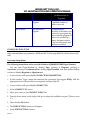
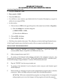
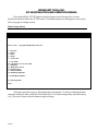
Installation and Operations Manual For the MC-16 Mega-Coupler 16 Copyright 1989 – 2004 by Broadcast Tools, Inc. All rights reserved. Except as permitted under the United States Copyright Act of 1976, no part of this document may be reproduced or distributed without permission All Specifications and features are subject to change without notice. Software Version 1.27 or above Manual update 02/23/2004 BROADCAST TOOLS, INC. MC-16 INSTALLATION AND OPERATION MANUAL INTRODUCTION. Thank you for your purchase of a Broadcast Tools, Inc., MC-16, MEGA-COUPLER 16. We will refer to this unit as the MC-16 thought out this manual. We’re confident that this product will give you many years of dependable service. This manual is intended to give you all the information needed to install and operate the unit. NOTE: This manual should be read thoroughly before installation and operation. SAFETY INFORMATION Only qualified personnel should install broadcast Tools products. Incorrect or inappropriate use and/or installation could result in a hazardous condition. CAUTION: Broadcast Tools products, as with any electronic device, can fail without warning. Do not use this product in applications where a life threatening condition could result due to failure. WHO TO CONTACT FOR HELP If you have any questions regarding this product, or you need assistance, please contact your distributor from whom you purchased this equipment or contact us directly. If you would like more information about Broadcast Tools, Inc., products, you may reach us at: Broadcast Tools, Inc. 131 State Street Sedro Woolley, WA 98284-1503 USA Voice Fax 360 . 854 . 9559 360 . 854 . 9479 Internet Home Page www.broadcasttools.com E-mail [email protected] Thank you for choosing Broadcast Tools! PAGE 2 BROADCAST TOOLS, INC. MC-16 INSTALLATION AND OPERATION MANUAL WARRANTY. LIMITED WARRANTY The term “Buyer” as used in this document refers to and includes both (but only) (a) any person or entity who acquires such an item for the purpose of resale to others (i.e., a dealer or distributor of an item), and (b) the first person or entity who acquires such an item for such person’s or entity’s own use. Broadcast Tools warrants to each Buyer of any item manufactured by Broadcast Tools that the item will be free from defects in materials and workmanship at the time its is shipped by Broadcast Tools if the item is properly installed, used and maintained. EXCLUSIVE REMEDIES If Broadcast Tools is notified of in writing of a failure of any item manufactured by Broadcast Tools to conform to the foregoing Limited Warranty within one (1) year following the date of the Buyer’s acquisition of the item, and if the item is returned in to Broadcast Tools in accordance with Broadcast Tools’ instructions for confirmation by inspection of the defect (which at Broadcast Tools’ election may include, without limitation, a requirement that the Buyer first obtain a Return Authorization number from Broadcast Tools, that the Buyer furnish proof of purchase in the form of an invoice and/or receipt, and that the Buyer prepay all freight charges associated with any return of the item to Broadcast Tools using such freight service as Broadcast Tools reasonably may specify), Broadcast Tools will repair or replace the defective item, or will refund the purchase price paid by the Buyer for the item. Broadcast Tools shall have the exclusive right to choose between these alternative remedies. NO OTHER WARRANTIES OR REMEDIES TO THE MAXIMUM EXTENT PERMITTED BY APPLICABLE LAW, BROADCAST TOOLS AND ITS SUPPLIERS DISCLAIM ALL OTHER WARRANTIES, EITHER EXPRESS OR IMPLIED, INCLUDING BUT NOT LIMITED TO IMPLIED WARRANTIES OF MERCHANTABILITY OR FITNESS FOR A PARTICULAR PURPOSE; AND THE FOREGOING ALTERNATIVE REMEDIES SHALL BE EXCLUSIVE OF ALL OTHER REMEDIES. THIS LIMITED WARRANTY GIVES YOU SPECIFIC LEGAL RIGHTS. YOU MAY HAVE OTHER RIGHTS, WHICH VARY FROM STATE/JURISDICTION TO STATE/JURISDICTION. NO LIABILITY FOR CONSEQUENTIAL DAMAGES TO THE MAXIMUM EXTENT PERMITTED BY APPLICABLE LAW, NEITHER BROADCAST TOOLS NOR ANY OF ITS SUPPLIERS SHALL HAVE ANY LIABILITY FOR ANY SPECIAL, INCIDENTAL, INDIRECT, CONSEQUENTIAL OR PUNITIVE DAMAGES WHATSOEVER (INCLUDING, WITHOUT LIMITATION, ANY DAMAGES FOR LOST PROFITS, BUSINESS INTERRUPTION, LOSS OF DATA OR INFORMATION, COST OF CAPITAL, CLAIMS OF CUSTOMERS, OR ANY OTHER PECUNIARY LOSS) ARISING OUT OF THE USE OF OR THE INABILITY TO USE ANY ITEM SUPPLIED BY BROADCAST TOOLS), EVEN IF BROADCAST TOOLS HAS BEEN ADVISED OF THE POSSIBILITY OF SUCH DAMAGES HAVE ANY LIABILITY FOR ANY SPECIAL, INCIDENTAL, CONSEQUENTIAL, EXEMPLARY OR PUNITIVE DAMAGES. THIS LIMITATION OF LIABILITY APPLIES WHETHER A CLAIM IS ONE ALLEGING BREACH OF A CONTRACT OR WARRANTY, NEGLIGENCE OR OTHER TORT, FOR THE VIOLATION OF ANY STATUTORY DUTY, THE FAILURE OF ANY LIMITED OR EXCLUSIVE REMEDY TO ACHIEVE ITS ESSENTIAL PURPOSE, OR ANY OTHER CLAIM OF ANY NATURE. BECAUSE SOME STATES AND JURISDICTIONS DO NOT ALLOW THE EXCLUSION OR LIMITATION OF LIABILITY FOR INCIDENTAL OR CONSEQUENTIAL DAMAGES, THIS LIMITATION MAY NOT APPLY TO YOU. Broadcast Tools, Inc. 131 State Street Sedro Woolley, WA 98284-1503 USA Voice Fax Internet Home Page E-mail 360 . 854 . 9559 360 . 854 . 9479 www.broadcasttools.com [email protected] PAGE 3 BROADCAST TOOLS, INC. MC-16 INSTALLATION AND OPERATION MANUAL NOTICE TO THE USERS. PAGE 4 • This device may not be used on telco-operated coin phone lines. Party lines and privately owned coin-phones, which are subject to local State regulatory policies, and possible additional State special requirements. • The telephone utility company has the right to make changes to their network, which may affect the operation of your equipment, provided you are given adequate advance written notice to permit correct operation. • In case of operational problems, disconnect your unit by removing the modular plug from the telco jack. If your regular phone (or other device or system) still works properly, your MC-16 has a problem and must remain disconnected and officially serviced or returned for repairs. If upon the above disconnection your regular service still has problems, notify your telephone utility company that they may have a problem. Request prompt service, at not cost to you the user. If a problem is found in premises wiring not telco-installed, you are subject to a service charge. If a fault is in telco installed wiring, you may not be subject to a service charge. • Unless otherwise noted in the User’s Manual (e.g.: fuses, etc.), user may not under any circumstances (in or out of warranty) attempt any service, adjustments or repairs on this unit (NO USER SERVICEABLE PARTS). It must be returned to Broadcast Tools, Inc. for all such work. Broadcast Tools, Inc. address and phone information is listed in this manual. • Special rules apply to equipment connected behind a PBX or KTS. BROADCAST TOOLS, INC. MC-16 INSTALLATION AND OPERATION MANUAL AUDIO SPECIFICATIONS. Table 1 Input Levels: Adjustable, Max + 24dbu, balanced bridging (Send to telephone line and (Aux to DTMF receiver). Output Levels: Adjustable, Off to + 4 dbu, @ 100 Ω, balanced output (Receive audio from telephone line). Logic: Microprocessor, EEprom user programming memory and high performance DTMF transceiver. Relays/OC: Sealed relays, utilizing 2 – form C on relays 1 & 2, 1 – form C on relays 3 through 16 and access. Contacts 30 vdc @ 500 ma. Open collector, @ 24 vdc @ 60 ma. NOTE: For safety, do NOT connect 120 Volt circuits to the relays. Busy: Compatible with 5 volt CMOS/TTL, open collector or contact closures. Max logic voltage 5 vdc. Connectors: I/O - Removable screw terminals, mates supplied Phone - Modular, RJ-11C phone line, cable supplied. Serial - Female DB-9, D-Sub, cable supplied Ringer equivalence: 0.2A (AC) / 3.0 (DC). Power Requirements: 16 to 18 Vac, @ 600 ma. 120 Vac wall transformer. Supplied Size: 19" X 1.75" X 4.50" (WHD) Weight: 3.0 lb. Shipping weight: 4.0 lb. PAGE 5 BROADCAST TOOLS, INC. MC-16 INSTALLATION AND OPERATION MANUAL Resource Specifications. Table 2 RESOURCE SPECIFICATIONS SPDT Relays, except K1 & 2 which are 2PDT Programs Maximum Commands per Program Macros Maximum Commands per Macro Number of Strings Maximum Characters per String Maximum Characters per Program Access Code Maximum Macro Depth (Macro calling Macro calling, Macro…) 17 32 30 64 64 64 32 4 5 PRODUCT DESCRIPTION . Front Panel The MC-16 is a 1-rack unit device (19”w x 1.75”h x 4.5”d). The front panel supports two selection switches, 4 LED indicators, Telco send and receive level controls, Auxiliary input level control and telephone line hybrid null control. Rear Panel Installation is simplified with pluggable screw terminal connectors. The MC-16 may be pre-wired and installed in minutes. The rear panel consists of one 9-pin D-Sub RS-232 connector, Telephone line modular connector, 2.1mm coaxial power connector and the removable screw connectors. Switches The front panel of the MC-16 contains a “SETUP” push-push switch used to put the MC-16 into (Set-up) configuration mode. The second push-push switch is used to seize the telephone line when the MC-16 is used to initialize a phone call. PAGE 6 BROADCAST TOOLS, INC. MC-16 INSTALLATION AND OPERATION MANUAL LED Indicators The MC-16’s front panel LED indicators provide operational display of the following information: The “RING” LED indicator will flash each time a ring is received. The “TONE” LED indicator will illuminate each time a valid DTMF tone is decoded. The “HOOK” LED indicator will light when the MC-16 picks up a call. The “POWER” LED indicator will light when power is applied to the MC-16 Audio Inputs Each of the 2 monaural inputs are balanced bridging (20KΩ) at a nominal line level of +4dBu. Single turn level controls are provided for each input. Audio Outputs The MC-16 provides a single balanced monaural output. The output is set at +4dBu @ 100 Ω and may be adjusted from off to + 4 dBu. Note: With –9dbm at the receive end of the telephone line. Relay Outputs The MC-16 contains 15 spdt and 2 dpst relays. Sixteen of the relays may be latched on, latched off or momentarily. The default pulse length is one hundred milliseconds. Note: Relay 17 will close when a valid access is entered. User Programming The MC-16 programming is stored in non-volatile memory. Configurations are programmed with selection dipswitches and computer commands. INSTALLATION. Supplied Items Please examine your MC-16 carefully for any damage that may have been sustained during shipping. If any is noted, please notify the shipper immediately. Retain the packaging for inspection by the shipper. The package contains the MC-16, 16.5 vac @ 600 ma power transformer, Installation manual, modular telephone cable and serial cable. Mounting The MC-16 is designed to be rack mounted in a standard 19” rack. It should be mounted in an area that is accessible from the rear and preferably away from sources of heat. We recommend before permanently installing the MC-16, you bench test and become familiar with the operation of the unit. PAGE 7 BROADCAST TOOLS, INC. MC-16 INSTALLATION AND OPERATION MANUAL Power supply connection The MC-16 requires 16 - 18 VAC @ 600 ma power. Plug the supplied wall transformer into a convenient 120 VAC power outlet. Plug the 2.1 mm coaxial power connector into the socket at the rear of the MC-16 labeled “Power”. Connecting the Audio Inputs, Outputs, Status inputs and OC/Relays The MC-16 interfaces to your equipment through depluggable rear panel screw terminals. Follow the legends for the desired audio, relay and control connections, which appear on the rear side of the printed circuit board. Remove each screw terminal, strip each conductor, and insert the conductor into the terminal and screw down the capture screw. The terminals accommodate wire sizes from 16 - 28 AWG solid or stranded wire. Connections may be made to the + and – audio inputs for balanced operation, or to the + input while grounding the - side for unbalanced input operation. Connections can be made to the + and – audio outputs for balanced operation, or to the + output and ground for unbalanced output operation. CAUTION: In no case should either the + or - outputs be connected to ground. CAUTION: Installation of the MC-16 in high RF environments should be performed with care. Shielded cable is suggested for all control, audio inputs and outputs. All shields should be tied to the “CH GND” terminal on each channel. The station ground should be connected to the chassis ground screw (CH1) located next to J1 as viewed from the rear. It is recommended that all cables connected to the MC-16 be looped through ferrite cores to suppress RF. Surge protection with RF filtering such as the Tripp Lite “ISOTEL 4 Ultra” or equivalent is also suggested for the power transformer and telephone line. The purchase of an inexpensive uninterruptible power supply (UPS) will provide back up in case of power outages. Serial Interface The Serial Interface is RS-232 with a female DB-9 connector. Only use the supplied serial cable to connect the MC-16 to your computer. Serial Control The MC-16 may operate at baud rates of 2400, 9600, 19200 and 38400 baud. The unit is shipped set for 9600 baud, with 8 data bits, no parity and one stop bit. 2400 9600 Default 19,200 38,400 PAGE 8 BROADCAST TOOLS, INC. MC-16 INSTALLATION AND OPERATION MANUAL MC-16 Operation. Explanation of Setup Items Programs The MC-16 supports 32 “programs.” Each program provides up to 30 commands, which may be activated by a remote user over the telephone interface. For example, a command might be “pulse relay 2 and send serial string 3.” The user would issue this command by pushing a key(s) on the telephone. Each command is issued by pressing a key(s) on the telephone. Keys 0-9, A-D, #, and “*” may be used, although few telephones have the “A-D” keys. Program Startup A user activates a program by dialing the MC-16’s phone number, waiting for the acknowledgement signal, then entering an asterisk (*), the program number (01 - 32), and then the access code (if any) for that program. If a mistake is made in entering the program number or access code, a single asterisk key (*) entry should be made, and the entire sequence restarted. At that time the program will generate another acknowledgement signal. At this time any program digit(s) may be entered to cause the appropriate action. The following example sequence accesses the program (including an error and its recovery) ΕEXAMPLE: Program: 02 Access Code: 1234 • • • • • • • • User dials the MC-16 phone number. MC-16 answers and then gives an acknowledgement signal User enters *02124 User realizes he has made a mistake, so press the asterisk key (*) to restart, and then start the sequence again: *021234 MC-16 responds with an acknowledgement signal User enters first command, in this case command 2 – by pressing key 2. The MC16 does the commanded function and sends the acknowledgement tone is enabled. (see below for commands). User continues to press command keys as required for various functions. Program Termination PAGE 9 BROADCAST TOOLS, INC. MC-16 INSTALLATION AND OPERATION MANUAL The program is terminated and the telephone disconnected when: • The user enters two “pound” (#) keys in sequence. • Or, if the unit is operating in CPC mode, when the CPC disconnect pulse is received by the MC-16 from your local telephone company. • Or, if the unit is not operating in CPC mode, when a specified time (see below) has elapsed with no commands being given. Program Operations As long as the program is operating, the user may activate any command by pressing the appropriate key(s) on the telephone. Macros It is often desirable to have more than one action occur when a single program command is given. A “macro” facility is provided to enable this. A macro is simply a list of commands. When the macro is invoked (started), either by a program command or by another macro, it executes the commands in the list one at a time until it has finished the list. ΕEXAMPLE: For example, we might want one command to pulse relay 4 and send serial string 6. The following illustrates an example macro to achieve this: Macro 3 Macro Step 1 2 MC-16 Action Pulse relay 4 Send string 6 NOTE: Notice that a macro can also call another macro if needed. That macro can call yet another. The maximum depth of these calls is 5 including the call from the program. There may be a maximum of 64 macros defined. PAGE 10 BROADCAST TOOLS, INC. MC-16 INSTALLATION AND OPERATION MANUAL Program and Macro Operations Programs can directly, or indirectly through macros, perform a number of operations on command. This following table defines those operations. Operation Relay Close Operation Action in Program Action in Macro (if different than in Program) Closes or pulses the specified relay. Specific action of relay is configured in the Relay Configuration menu. Action in Program Action in Macro (if different than in Program) Relay Open Opens or pulses the specified relay as determined by the relay configuration Send String Sends the specified string out the serial port Set Phone Audio On Sends audio from the TELCO Send input to the telephone Line. Set Phone Audio Off Stops sending audio to the telephone line. Hang Up Hangs up the telephone line. Do Nothing Disables associated Not Allowed in Macro command key Invoke Macro Executes the specified Executes the specified macro macro. When that macro completes, continues to the next operation in this macro. PAGE 11 BROADCAST TOOLS, INC. MC-16 INSTALLATION AND OPERATION MANUAL Operation Action in Program Delay Not Allowed in Program End of Macro Not Allowed in Program Action in Macro (if different than in Program) Delay macro execution for a specified number of tenths of seconds Completes macro execution. If the macro was invoked by a program, the macro ends the program. If macro was invoked by a macro, the macro returns to the invoking macro and continues execution. CONFIGURATION SETUP This section describes how to configure the MC-16, including programs, macros, strings, relays and miscellaneous parameters. While the MC-16 is in setup mode, it will not answer any calls. Accessing Setup Menus The following instructions are for use with Windows 95/98/ME/NT/2000 HyperTerminal. You can start HyperTerminal by clicking Start, pointing to Programs, pointing to Accessories, pointing to Communications, clicking HyperTerminal, and then double-clicking on the icon labeled Hypertrm or Hypertrm.exe. • A new window will open labeled CONNECTION DESCRIPTION. • In this window, Type a name that describes the connection (We suggest BTI96), click the appropriate icon, if desired this is not required, and then click OK. • A new window will open labeled CONNECT TO. • At the CONNECT TO screen, 1. Move your cursor to the CONNECT USING box 2. Press the down arrow on the right of the box to select the available com port (“Direct to com x”), 3. Then click the OK button. • The PORT SETTING window will appear. • At the PORT SETTING window, PAGE 12 BROADCAST TOOLS, INC. MC-16 INSTALLATION AND OPERATION MANUAL Accessing Setup Menus (cont) 1. Change the baud rate to 9600, 2. Flow control to NONE 3. Then click OK button. • You will have a new window open labeled with the Connection Description you typed in earlier (in our example, BTI96). • At this window 1. Click on the word FILE at the upper left portion of the menu bar and click on Properties. i) Click the Settings tab, and then change the (1) EMULATION to ANSI, (2) Then click the OK button. 2. Click on FILE, click Save. 3. Click on FILE, click Exit. • Click Yes, when asked to disconnect. This will place you back at the HyperTerminal screen At the HyperTerminal screen, find the Icon and/or file you named and double click on it. SERIAL PORT TROUBLESHOOTING A Build a loop-back “TESTER” by purchasing a “FEMALE” 9 pin D-sub solder cup connector (Radio Shack, CompUSA, Local Electronic Store, etc). B Solder a jumper between pins 2 & 3. C Try typing on the keyboard with nothing connected to the computer’s com port. You shouldn’t see any characters. If you do, the “ECHO typed characters locally” is checked (ON)” in the ASCII settings in HyperTerminal. Turn this OFF (Uncheck) and retest. D Plug the “TESTER” into the com port under test E Try typing on the keyboard, if you’re using the correct com port, each character typed will be displayed. F If this test fails, try changing com ports on the communication program until you find the correct port. When a working com port is found, follow the instructions below. Tool Tip: With some communication programs, any change made to the program settings requires you to save the changes, exit the program and restart the program. PAGE 13 BROADCAST TOOLS, INC. MC-16 INSTALLATION AND OPERATION MANUAL Press and hold the SETUP button on the front panel, press the space bar on your keyboard, and then release the SETUP button. The initial setup menu will appear on the screen. (See next page for sample screen). Master Setup Menu Menu MC-16 - 01.27 Master Setup Menu Copyright 1999,Broadcast Tools, Inc 1 - Programs 2 - Macros 3 - Relays 4 - Strings 5 - Access Codes A - CPC Mode B - Call Timeout for Non-CPC Mode C - Baud Rate D - Rings Before Answer E - Response Mode F – Dump EEPROM R - Reinitialize EEPROM T - Enable Hybrid Balance Q - Exit Setup Mode Cmd: This menu provides access to all configuration information. To select an individual item, enter the number or letter to the left of the menu line. To exit from setup mode, enter the letter q or Q. The case of letters does not matter except in strings. PAGE 14 BROADCAST TOOLS, INC. MC-16 INSTALLATION AND OPERATION MANUAL Initial Setup Menu Details Table 5 1 2 3 4 5 A B C D E F R T Q Description of Item Selected Programs (01 to 32) – the programs define the telephone key (DTMF) commands. Each program contains one operation or macro invocation per DTMF key(s). Macros – each macro contains a series of operations to be performed by the MC-16. Maximum 64. Relays – each relay can operate in one of four modes. This selection selects the modes. Strings – each string is a group of ASCII and/or 7-bit binary characters, which may be sent out the serial port as a program or macro operation. Maximum 32 Access Codes – each program has an access code required to access it. (Maximum 4 digits) CPC Mode – in CPC mode the MC-16 automatically hangs up when it detects a disconnect pulse from your local telephone company. This occurs (if the telephone company provides the service) when an incoming call is disconnected. If CPC mode is off, the MC-16 hangs up after a set period of time without any commands being issues. This selection allows CPC mode to be turned on or off. Call Timeout for non-CPC mode. This allows the hang-up timer to be set to a specified number of minutes. Maximum 20 minutes. Baud Rate – the serial interface may operate at any of four serial speeds. This entry selects the speed. This speed applies both to the sending of serial strings, and future setup sessions. Rings Before Answer – the MC-16 will wait a set number of rings before answering the telephone. This entry sets that number. Maximum 20 rings. Response mode – Enable or disable the acknowledgment (beep) tone per program Dump EEPROM – The MC-16 downloads all configuration information in the Electrical Erasable PROM to a connected PC. Reinitialize EEPROM – The MC-16 stores all configuration information in an Electrical Erasable PROM. This entry resets the configuration to factory defaults or allows a configuration upload from a connected PC. Hybrid Balance Tone – the MC-16 can generate a single or multiple tones to be used while balancing the telephone interface hybrid. This entry activates and allows control of that tone. Exit Setup Mode – entering Q or q will erase the screen and terminate setup mode. If the serial speed was changed during this setup session, the new speed will now be activated. Program Setup Menus PAGE 15 BROADCAST TOOLS, INC. MC-16 INSTALLATION AND OPERATION MANUAL After the Program is selected, the following menu is displayed: Example Program Setup Menu MC-16 - 01.27 Table 6 Copyright 1999,Broadcast Tools, Inc Pgm Setup ---01--0-AUD ON 1-C01 2-C02 3-C03 4-C04 5-O01 6-O02 7-O03 8-O04 9-O04 A-C05 B-S11 C-S12 D-C01 *#0- ---02--0-C01 1-O01 2-C02 3-M02 456789AB-M01 CD*-C01 #0- ---03--0123456789ABCD*#0- ---04--0123456789ABCD*#0- ---05--0123456789ABCD*#0- ---06--0123456789ABCD*#0- ---07--0123456789ABCD*#0- Enter: + for next page, - for prev page, Item Num: This menu displays the first 7 programs. To display other programs, press the Plus (+) or Minus (-) key. Each program is shown in a separate column. The key corresponding to the command is on the left, then a “-“, then the operation code itself. See the Operations Decode Table For Macros and Programs to see how to decode the operation codes. PAGE 16 BROADCAST TOOLS, INC. MC-16 INSTALLATION AND OPERATION MANUAL Examples from the menu displayed above: Example Program Operation Entries Program Number 01 Command Key * Displayed 02 3 3-M02 *-S01 Table 7 Meaning Send string 01 when the asterisk (*) key is pressed on the telephone. Execute Macro 02. To modify or create a specific program, enter it’s number (such as “02”). To go back to the previous menu, press the Enter key. When a program has been selected, a screen like the following is displayed. It shows only the program selected, and allows commands in that program to be edited. Example Program Edit Screen MC-16 - 01.27 Table 8 Copyright 1999,Broadcast Tools, Inc Pgm 01 - Edit Screen 0-AUD ON #11-C01 #22-C02 #33-C03 #44-C04 #55-O01 #66-O02 #77-O03 #88-O04 #99-O04 #AA-C05 #BB-S11 #CC-S12 #DD-C01 #*-S01 *#0Enter Key (0-9A-D* or #+key), or X to erase: • • • To erase all commands in the program, press X. To return to the previous menu, press Q or Enter. To edit or enter a command, enter the command key(s) (0-9,A-D, #, ∗) to display the Command Edit Dialog (See next page). PAGE 17 BROADCAST TOOLS, INC. MC-16 INSTALLATION AND OPERATION MANUAL Example Command Edit Dialog Table 9 Enter Key (0-9A-D * or # + key), or X to erase: Edit Cell 8 => 8-O04 D - Do Nothing H - Hang Up M - Invoke Macro P - Set Phone Audio R - Set Relay S - Send String Q - Quit Edit Cmd? The above screen allows modification of a command. In this instance, it allows the command (cell) 8 to be modified. Some of the selections will result in additional dialogues being displayed. When a cell modification is complete, this dialog is displayed for the next cell. Actions allowed: PAGE 18 • Set command to do nothing at all – press D. This will prevent the associated key from doing anything. • Set command to hang up the phone – press H. • Set command to invoke a macro – press M. You will be prompted to enter the macro number. • Set command to control audio-to-telephone link – press P. You will be prompted to enter Y if the command is to turn on the audio link, or N to turn it off. • Set command to control a relay – press R. You will be prompted as follows: • Relay Num (01-16): (enter the relay number – two digits) • Relay Close (C) or Relay Open(O) (C/O)? (Enter the appropriate letter) • Set command to send a string – press S. You will be prompted for the string number. • Return to previous menu – press Q or ESC. BROADCAST TOOLS, INC. MC-16 INSTALLATION AND OPERATION MANUAL Macro Setup Menus The Macro Setup Menus provide the capability to examine and set up Macros. A macro is a list of commands which, when invoked by a command, executes until it is complete. Macros allow all program commands, and also the additional Delay command, which causes the macro to pause for a specific period of time. Example Macro Setup Menu MC-16 - 01.27 Table 10 Copyright 1999,Broadcast Tools, Inc Macro Setup - Only First 16 Commands Shown ---01--- ---02--- ---03--- ---04--- ---05--- ---06--- ---07--01-S10 01-S12 0101-DLY:1.2 01010102-S01 02-DLY:2.0 0202-M01 02020203-M02 03-S13 0303-AUD ON 03030304-C03 040404-AUD OFF 04040405-DLY:1.0 050505-C01 05050506-S11 060606-O01 06060607070707-S01 07070708080808-HANG UP 0808080909090909090910101010101010111111111111111212121212121213131313131313141414141414141515151515151516161616161616Enter: + for next page, - for prev page, Item Num: The Macro Setup Menu shows the first group of macros and the first commands in that macro. You can: • To move to the next page of macros – press the plus (+) key. • To move to the previous page of macros – press the minus (-) key. • To display all commands in a macro, and enable editing of that macro - enter its two digit macro number. • To return to the previous menu -press Q or ESC. PAGE 19 BROADCAST TOOLS, INC. MC-16 INSTALLATION AND OPERATION MANUAL Once a macro has been selected by entering it’s two-digit macro number, a page is displayed to edit that macro. It displays all commands in the macro, and enables editing or erasing any cell (command) in the macro. Example Menu to Set Up One Macro MC-16 - 01.27 Table 11 Copyright 1999,Broadcast Tools, Inc MACRO - Edit Screen 01-S10 17-S17 334902-S01 18-S18 345003-M02 19-S19 355104-C03 20365205-DLY:1.0 21375306-S11 22385407233955082440560925415710264258112743591228446013294561143046621531476316324864Enter Cell Num(01-64), or X to erase: • • • • To erase the entire macro – press X. To redisplay the macro – press S. To return to the previous menu – press Q or ESC. To edit one cell of the macro – enter the two-digit cell number. The Edit Macro Cell dialog will be displayed. CAUTION: Do not leave blank in-between cells before the last one. The macro will stop executing at the first blank cell. In the example above, cells 17, 18 and 19 will never be executed. The macro will stop at cell 06. PAGE 20 BROADCAST TOOLS, INC. MC-16 INSTALLATION AND OPERATION MANUAL The edit macro cell dialog allows you to edit one cell of a macro. It displays the contents of that cell Example Edit Macro Cell Dialog Table 12 Edit MacroCell 06 => 06-S11 D - Delay E - End of Macro B - Emit Beep H - Hang Up M - Invoke Macro P - Set Phone Audio R - Set Relay S - Send String Q - Quit Edit Cmd? The cell can be set to: • Delay execution of the rest of the macro – press D. You will be prompted for the two digit number of tenths of seconds of that delay. Example: 10 = 1 second. • End execution of the macro – press E. Note that this is not necessary if there is no room to add it. Otherwise the cell immediately following this entry must be set to End execution. It will display as blank. • Set command to emit a confirmation “Beep” tone. Press B • Set command to hang up the phone – Press H. • Set command to invoke a macro – Press M. You will be prompted to enter the two digit macro number of another macro to be invoked. When it ends execution, the current macro will continue where it left off. • Set command to control the send audio-to-telephone line – press P. You will be prompted to enter Y if the command is to turn on the audio link, or N to turn it off. • Set command to control a relay – press R. You will be prompted as follows: • Relay Num (01-16) (enter the relay number – two digits) • Relay Close(C)or Relay Open(O) (C/O) (enter the appropriate letter) • Set command to send a string – Press S. You will be prompted for the string number. • To return to the previous menu – Press Q or ESC. PAGE 21 BROADCAST TOOLS, INC. MC-16 INSTALLATION AND OPERATION MANUAL Relay Setup Menu Relays on the MC-16 can be set to one of the following modes: MC-16 Relay Modes Table 13 Mode Meaning Hold (Latch) Close command: close relay and keep it closed. Open command: open relay and keep it opened. Interlock Relays operate in even-odd pairs. Thus, for an example, if relay 2 is set to interlock, relay 3 will also be interlocked with it. In an interlocked pair: Close command: close the specified relay and keep it closed. Open the other relay of the pair and keep it opened. If one receives the open command, it opens and stays open. The other relay will then close and stay closed. Momentary On When the close command is issued, the relay pulses for 100 Tone milliseconds as soon as the DTMF tone is detected. Momentary When the close command is issued, the relay pulses for 100 After Tone milliseconds as soon as the DTMF tone has ceased. The relay setup menu is displayed when option 3 is selected from the Master Setup Menu. The menu shows the current state (whether the relay is opened or closed) and current mode for each relay. Interlocked pairs consist of a relay in the left column and the relay on the same line in the right column. An example is: Example Relay Setup Menu Table 14 MC-16 - 01.27 Copyright 1999,Broadcast Tools, Inc Relays 01 - C 03 - O 05 - O 07 - O 09 - O 11 - O 13 - O 15 - O - Interlock Mom On Tone Hold Mode Hold Mode Hold Mode Hold Mode Hold Mode Hold Mode 02 - O - Interlock Secondary 04 - O - Mom After Tone 06 - O - Hold Mode 08 - O - Hold Mode 10 - O - Hold Mode 12 - O - Hold Mode 14 - O - Hold Mode 16 - O - Hold Mode Relay Num(01-16)? To set the mode of a relay, enter its two-digit number. If the mode will be Interlock, its paired relay will also be configured as Interlock. This will display the Relay Setup Dialog (see example below). PAGE 22 BROADCAST TOOLS, INC. MC-16 INSTALLATION AND OPERATION MANUAL To return to the previous menu, enter Q or ESC. Example Relay Setup Dialog Table 15 Relay 05 Setup A - Set Relay to Close When Last Character of Command Starts B - Set Relay to Close After Last Character of Command Done C - Set Relay to Hold State D - Set Relay to Interlock with Neighbor This example sets up relay number 05. • To set relay to close when last character of command starts – Press A. • To set relay to close when last character of command ends – Press B. • To set relay to hold mode – Press D. • To set relay to interlock mode – Press D. This will also set the paired relay to interlock mode. PAGE 23 BROADCAST TOOLS, INC. MC-16 INSTALLATION AND OPERATION MANUAL String Setup Menu The MC-16 can send ASCII strings from its serial port at the configured bit rate. The String Setup Menu is used to define those strings. The strings can contain both printable characters, and hexadecimal encoded binary characters. It is common to end a string with a ”carriage return”. This is encoded in hexadecimal (per the ASCII standard) as 0D (note: this starts with the number zero rather than the letter oh). See Appendix II - ASCII to HexaDecimal Conversion Table. Example String Setup Menu MC-16 - 01.27 Copyright 1999,Broadcast Tools, Inc String Setup 01:SP C,S,2\0D@AM C,0\0D 02: 03:SETAUDIO 1 S SR1 0\0D 04: 05:LOAD FILE,3456\0D 06: 07: 08: 09: 10: 11: 12: 13: 14: 15: 16: + for Next page, - for Prev page, String Num: The String Setup Menu shows the first group of macros and the first commands in that macro. You can: • To move to the next page of macros – press the plus (+) key. • To move to the previous page of macros – press the minus (-) key. • To display all commands in a macro, and enable editing of that macro - enter its two digit macro number. • To return to the previous menu -press Q or ESC.. PAGE 24 BROADCAST TOOLS, INC. MC-16 INSTALLATION AND OPERATION MANUAL Access Codes Setup Menu The Program Access Code Setup Menu provides the way to view, set or delete program access codes. NOTE: Programs do not require access codes. Example Program Access Code Setup Menu MC-16 - 01.27 Table 16 Copyright 1999,Broadcast Tools, Inc Pgm Access Code Setup 01 [0123] 17 [ ] 02 [ ] 18 [ ] 03 [ ] 19 [ ] 04 [ ] 20 [ ] 05 [ ] 21 [ ] 06 [ ] 22 [ ] 07 [ ] 23 [ ] 08 [ ] 24 [ ] 09 [ ] 25 [ ] 10 [ ] 26 [ ] 11 [ ] 27 [ ] 12 [ ] 28 [ ] 13 [ ] 29 [ ] 14 [ ] 30 [ ] 15 [ ] 31 [ ] 16 [ ] 32 [ ] Pgm Num? This example shows a system where only program 01 has an access code. The other programs do not require an access code. The program one access code is 0123. To run program 01, call the unit on the phone, wait for the acknowledgement tone, and then enter “*010123”. To run program 02, call the unit on the phone, wait for the acknowledgement tone, and then enter “*02”. To set or delete an access code, enter the two-digit program number. You will be prompted with: Enter Access Code. Press ENTER when done: To set the access code, type the string (use only those keys on the telephone pad – 0-9, * and, if a 16 button phone is to be used, A-D. If you type fewer than four characters, you will need to press ENTER to complete the access code entry. To delete the access code, press ENTER at the prompt.To return to the previous menu, press Q or ESC. PAGE 25 BROADCAST TOOLS, INC. MC-16 INSTALLATION AND OPERATION MANUAL Setting CPC Mode The “CPC” mode determines whether the unit will automatically hang-up after a caller disconnects (CPC Mode On), or will require a manual hang-up command or timeout CPC Mode Off). To change the CPC mode, enter A from the main menu. You will be prompted with: CPC Mode is Now ON CPC Mode On (Y/N)? Notice that the current status of the CPC mode is displayed. Enter Y to turn the mode on, or N to turn it off. Setting Call Timeout for Non-CPC Mode In non-CPC mode, if a caller disconnects without entering the hang-up command (##), the unit will remain off hook. In this case, the call timeout is needed to cause it to automatically hang up. The call time-out is the number of minutes after the last command before the unit will hang up automatically. To set the call timeout value, enter B on the main menu. You will be prompted with: • Current Timeout is 20 Minutes • Num of minutes for call timer (00-20)? Notice that the current value of the timer is displayed. Enter the two-digit number of minutes desired. Entering 00 will disable the time-out function. NOTE: Maximum time-out is 20 minutes. Setting Baud Rate The baud rate for the setup menu can be set to any of four speeds. The default is 9600 baud. To change the baud rate, enter C on the main menu. You will be prompted with: Baud Rate is 9600 1 - 2400 2 - 9600 Default 3 - 19200 4 - 38400 Speed (1-4)? Notice that the current baud rate is displayed. To change the baud rate, enter the corresponding number. PAGE 26 BROADCAST TOOLS, INC. MC-16 INSTALLATION AND OPERATION MANUAL Setting Number of Rings Before Answer To set the Number of Rings before answer, select D from on the main menu. You will be prompted with: Rings before Answer now:01 Rings (01-20)? Notice the current value is shown – in this case 01, which means answer on the first ring. To change this value, enter two digits 01 through 20. NOTE: Maximum number of rings is 20. Setting the Program Response Mode Each program may be programmed to give audible responses to commands, or not. To set the response mode, enter E on the main menu. You will be prompted with: Program Numbers (01-32)? Enter the two-digit program number. You will then be prompted with: Responses are on - Disable (Y/N)? Notice that the current response state of the program is shown. Enter Y to change the mode, N to leave it the same. Re-Initializing the MC-16 Configuration (EEPROM) All configuration information is stored in the MC-16’s non-volatile electrically erasable memory (EEPROM). To restore configuration to factory defaults, enter R on the main menu. You will be prompted with: Factory Reset - Code? You must exactly enter in capital letters (upper case) the following BTI. This code is required to prevent inadvertent re-initialization. Once the I has been typed in, the unit will begin re-initializing with the output: Reset EEPROM:.......... As it is initializing, it will output dots to show it is still working. When it is complete, it will display the main menu. PAGE 27 BROADCAST TOOLS, INC. MC-16 INSTALLATION AND OPERATION MANUAL To Download an MC-16 Configuration to a connected PC 1) Connect the MC-16 to your PC and start HyperTerminal at 9600 baud 2) Hold down the SETUP button and press the PC’s space bar This will bring up the setup menu 3) Enter F (for Dump EEPROM) Unit will respond with "Prepare Capture” press the ENTER key. 4) At the Hyper terminal screen, 1-Click Transfer->Capture Text 2-Type in a file name (example: mc16.txt). 3-Click "Start" 4-Hit the ENTER key Unit will respond with a long stream of text. When it is done, it will display "End Capture, hit ENTER" 5) On Hyper terminal 1-Click Transfer->Capture Text->Stop 2-Hit the ENTER key At this point, the file (mc16.txt for example) will hold the configuration. To Set up an MC-16 from a downloaded configuration: 1) Connect to the MC-16 using HyperTerminal at 9600 baud 2) Hold down the SETUP button and press the terminal space bar. This brings up the setup menu 3) Type R to reset EEPROM. Unit will respond with "Factory Reset - Code?" 4) Type BTI (ALL CAPS) and then press enter. The MC-16 will response with Init EEPROM and then a string of spaces. When it is complete, it will display the menu again. 5) Type Q to exit the menu 6) Click Transfer->Send Text File 7) Click on the file name with the configuration desired (example:mc16.txt) 8) Click on "Open" 9) The file will be sent. A series of dots will display during transmission. When the setup is complete, the unit will respond with a Done message. CAUTION: If the letter "E" appears on the screen instead of one of the dots, it indicates a transmission error. This entire procedure, starting at step 1 should be repeated. If errors continue, reduce the baud rate. PAGE 28 BROADCAST TOOLS, INC. MC-16 INSTALLATION AND OPERATION MANUAL Balancing the Hybrid The telephone hybrid in the MC-16 may need to be balanced in order to match your telephone line. The MC-16 can generate a hybrid balance tone for that purpose. The hybrid balance procedure is: 1. Enter T on the main menu. You will be prompted with: Next call will be for hybrid setup - press ENTER: 2. Press ENTER to continue. 3. You will now see the main menu. Press Q to exit setup mode. 4. Dial the unit’s telephone number. The unit will answer on the first ring. After it’s normal greeting tone, it will start sending the hybrid balance tone (approx 1000 Hz). The unit will stay on line and will continue generating the tone until either: If it is in CPC mode, you hang up; or If it’s not in CPC mode, after one minute. 5. Balance the hybrid by connecting an audio voltmeter or headset to the audio output. You will want to slowly adjust the “NULL” control for the lowest possible reading or tone. 6. Hang up the phone when done. On subsequent calls the unit will behave as normal. Exiting Setup Mode To exit setup mode, you must return to the main menu if any other menus are showing (except in cases noted, this can be done by pressing the ENTER key until the main menu is displayed. Then press Q and the unit will return to normal operation. PAGE 29 BROADCAST TOOLS, INC. MC-16 INSTALLATION AND OPERATION MANUAL Connecting the MC-16 to external equipment NOTE: All connections are labeled on the rear edge of the printed circuit board. • Relay connections for relays 1 through 16 and the “ACCESS” relay. Removable screw terminals are provided. • RS-232 port: A female DB-9 D-Sub connector and straight- through serial cable are provide for connection to a PC. Default: 9600 8 N 1, Flow control = NONE and emulation set to ANSI. • Telephone line: A modular jack is provided for connection to a telephone line. The line cord is provided. • Power: A 2.1mm “barrel” connector is provided for 16 to 18 V AC ONLY @ 600ma power. The wall transformer is supplied. • Open collector transistor outputs are supplied for “RING” and “TONE” status. These outputs go low whenever a ring or tone is detected. Removable screw terminals are provided. • The remote seize input is labeled “SEIZE”. A low on this input causes the MC-16 to seize the telephone line. Removable screw terminals are provided. • The remote busy input is labeled “BUSY”. A low on this input forces an Off-Hook condition. Removable screw terminals are provided. • The balanced audio input feed to the phone line is labeled “TEL IN”. The level is adjustable from the front panel. Removable screw terminals are provided. • The balanced audio input feed to the DTMF decoder is labeled “AUX”. The level is adjustable from the front panel. Removable screw terminals are provided. • The balanced audio output feed from the telephone line is labeled “TEL OUT”. The level is adjustable from the front panel. Removable screw terminals are provided PAGE 30 BROADCAST TOOLS, INC. MC-16 INSTALLATION AND OPERATION MANUAL Appendix I - Operations Decode Table for Macros and Programs Operations Decode Table For Macros and Programs Code Allowed in Meaning Example Program DLY:x.x N Delay S.S x.x seconds. DLY:1.2 M:xx Y Invoke Macro number xx. M01 AUD ON Y Send Audio Input to Telephone Interface AUD OFF Y Stop Sending Audio Input to Telephone Interface Cxx Y Close or Pulse Relay xx C01 Oxx Y Open or Pulse Relay xx O01 Sxx Y Send String xx S01 HANG UP Y Hang Up Telephone and End Program Session Meaning Delay 1.2 Secs Invoke Macro number 01 Close or Pulse Relay 01 Open or Pulse Relay 01 Send String number 01 Appendix II - ASCII to HexaDecimal Conversion Table Hexadecimal Code 07 08 09 0A 0C 0D 1B 7F Meaning BELL – on an ASCII terminal, make a beep. Backspace – erase the previous character Horizontal Tab – tab key. Line Feed. Form Feed – end of a page. Carriage Return – the Enter key. ESC – The ESC key. DEL – The DEL key. PAGE 31