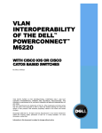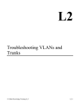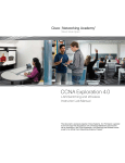
1
INC
®
Installation and Operation Manual
USC-16/SG
Universal Satellite Channel Controller
StarGuide II / III Upgrade Guide
Firmware Version 1.8
Manual Update: 04/04/04
SG, Virtex “StarGuide II or III“ are ™ of StarGuide Digital Networks, Inc.
Wegener “Unity 4000” is ™ of Wegener Communications.
“Premiere” is a ™ of Premiere Radio Networks.
“WW1” is a ™ of Westwood One Radio Networks
“ABC” is ™ of ABC Radio Networks
Due to the dynamic nature of product design, the information contained in this
document is subject to change without notice. Broadcast Tools, Inc., assumes no
responsibility for errors and/or omissions contained in this document. Revisions
of this information or new editions may be issued to incorporate such changes.
Broadcast Tools® is a registered trademark of Broadcast Tools, Inc.
Copyright, 1989 - 2006 by Broadcast Tools, Inc. All rights reserved.
No part of this document may be reproduced or distributed without permission.
Visit www.broadcasttools.com for important product update information.
USC-16/SG Installation and Operation Manual
INTRODUCTION
Thank you for your purchase of a Broadcast Tools® USC-16/SG. We're confident that this product will give you many years of dependable service. This manual is intended to give you all the information needed to install and operate the unit.
SAFETY INFORMATION
Only qualified personnel should install Broadcast Tools® products. Incorrect or
inappropriate use and/or installation could result in a hazardous condition.
Broadcast Tools, Inc., is unable to support NON-Broadcast Tools software, hardware or
NON-Broadcast Tools computer/hardware/software problems. If you experience these
problems, please research your hardware/software instruction manuals or contact the manufacturers technical support department.
WHO TO CONTACT FOR HELP
CAUTION!
Broadcast Tools®
Products, as with any
electronic device, can
fail without warning.
Do not use this product
in applications where a
life threatening condition
could result due to failure.
NOTE:
This manual should be
read thoroughly before
installation and operation.
If you have any questions regarding your product or you need assistance, please contact your distributor from whom you purchased this equipment.
If you would like more information about Broadcast Tools® products, you may
reach us at:
Broadcast Tools, Inc.
131 State Street
Sedro-Woolley, WA 98284-1540 USA
Voice: 360 . 854 . 9559
Fax: 360 . 854 . 9479
WEBSITE:
Visit our web site for
product updates and
additional information.
Internet Home Page: www.broadcasttools.com
E-mail:
[email protected]
THANK YOU FOR CHOOSING
BROADCAST TOOLS® BRAND PRODUCTS!
SECTION TITLE
e-mail: [email protected] v o i c e : 360.854.9559 fax: 360.854.9479
2
USC-16/SG Installation and Operation Manual
PRODUCT DESCRIPTION
The USC-16/SG is an upgrade for the USC-16, Universal Satellite Channel
Controller. After the upgrade has been installed, the USC-16 will be referred to as
the USC-16/SG. The USC-16/SG is completely programmed with services of most
StarGuide affiliates. The USC-16/SG is field programmable to switch audio ports,
audio port channel swapping, services, providers and carriers on the StarGuide II and
III satellite receivers. The USC-16/SG, when operated with contact closures or serial control, will provide sixteen, 31 - character string selections for the StarGuide II or
III receivers. Programming of the USC-16/SG is straightforward. Using a NONDEDICATED computer along with the communication program (HyperTerminal)
included with the Windows 95/98/ME/2000/NT operating system. After the desired
locations have been programmed, the USC-16/SG may be unplugged and installed.
The program information is stored in non-volatile memory.
UNPACKING AND HANDLING
Please examine your USC-16/SG for any damage that may have been sustained during shipping. If any is noted, please notify the shipper immediately. Retain the
packaging for inspection by the shipper. The package should contain the USC16/SG upgrade chip, 1 - modular cable /w 9 pin male D-sub “SG-9” serial adapter
and this manual.
UPGRADE PROCEDURE
Please follow these steps:
1 Remove power and ALL connections from the USC-16.
2 Remove the cover.
3 Be sure to follow proper “STATIC SENSISTIVE DEVICE” procedures with
the IC in position U3.
4 Locate U3 and carefully remove.
*NOTE: Use an IC puller or small (Greenie) screwdriver to pry out U3.
5 Carefully insert the USC-16/SG upgrade IC into U3.
*NOTE: Be sure to observe the correct pin orientation.
6 Replace the cover and reattach all cabling.
7 Remove JP-3, if installed
8 Follow the procedure below.
WEBSITE:
Visit our web site for
product updates and
additional information.
PRODUCT DESCRIPTION
e-mail: [email protected] v o i c e : 360.854.9559 fax: 360.854.9479
3
USC-16/SG Installation and Operation Manual
COMPILING THE NEEDED INFORMATION TO PROGRAM THE
USC-16/SG
1 Have your receiver installed and authorized. Be sure you can manually
select the program(s) from the receiver’s front panel keyboard and have an
audio monitor attached to the correct audio port.
2 Request the provider number(s) for the program(s) you will be receiving.
3 Request the service number(s) for the program(s) you will be receiving.
4 Determine what audio port(s) you plan to use.
5 Record this information for later use.
TESTING YOUR STARGUIDE RECEIVER WITH YOUR
COMPUTER’S SERIAL (COM) PORT
• A new window will open labeled CONNECTION DESCRIPTION.
• In this window, Type a name that describes the connection (We suggest BTI96),
click the appropriate icon, if desired this is not required, and then click OK.
• A new window will open labeled CONNECT TO.
• At the CONNECT TO screen,
1. Move your cursor to the CONNECT USING box
2. Press the down arrow on the right of the box to select the available com port
(“Direct to com x”),
3. Then click the OK button.
• The PORT SETTING window will appear.
• At the PORT SETTING window,
1. Change the baud rate to 9600,
2. Flow control to NONE
3. Then click OK button.
You will have a new window open labeled with the Connection Description you
typed in earlier (in our example, BTI96).
• At this window
1. Click on the word FILE at the upper left portion of the menu bar and click on
Properties.
i) Click the Settings tab, and then change the
(1)
EMULATION to ANSI,
(2)
Then click the OK button.
2. Click on FILE, click Save.
3. Click on FILE, click Exit.
4. Click Yes, when asked to disconnect. This will place you back at the
HyperTerminal screen
• At the HyperTerminal screen, find the Icon and/or file you named and double click
on it.
! TIP
Take advantage of your program provider and receiver
manual. They are great
resources!
This step is required to confirm that the communication
program and StarGuide II /
III receiver are configured
properly. The following
instructions are for use with
Windows 95/98/ME/NT/2000
HyperTerminal. You can
start HyperTerminal by
clicking Start, pointing to
Programs, pointing to
Accessories, pointing to
Communications, clicking
HyperTerminal, and then
double-clicking on the icon
labeled Hypertrm or
Hypertrm.exe.
PRODUCT DESCRIPTION
e-mail: [email protected] v o i c e : 360.854.9559 fax: 360.854.9479
4
USC-16/SG Installation and Operation Manual
TESTING THE STARGUIDE II or III RECEIVER
1 Set your receivers M & C serial port for 9600,8,N,1 via the receivers front panel
keyboard.
2 Connect a Male - Female, DB-9 straight-through serial cable between the M & C
port on the receiver and your computers com port.
* NOTE: Do not use the cables supplied by us!
CAUTION!
Broadcast Tools
products, as any electronic device, can fail
...
3 On your computer keyboard, type the following command: VER and press the
ENTER key.
4 If the two are communicating, the details of the current receiver’s software and
other information will be displayed.
5 If your test was successful, remove the Male - Female, DB-9 straight through serial cable from the computer and receiver; proceed to the section labeled “Connecting
the USC-16/SG to your computers serial port”. If your test failed, follow the troubleshooting steps A through G that follows.
TROUBLESHOOTING
A. Build a loop-back “TESTER” by purchasing a “FEMALE” 9 pin D-sub solder
cup connector (Radio
Shack, CompUSA, Local Electronic Store, etc).
B. Solder a jumper between pins 2 & 3.
C. Try typing on the keyboard with nothing connected to the computer’s com port.
You shouldn’t see any characters. If you do, the “ECHO typed characters locally”
is checked (ON)” in the ASCII settings in HyperTerminal. Turn this OFF
(Uncheck) and retest Step C.
NOTE:
If you find that a failure
is traced to the receiver
and ALL receiver troubleshooting has failed.
contact the receiver
manufacture.
! TIP
With some communication programs, any
change made to the program settings requires
you to save the changes,
exit the program and
restart the program.
D. Plug the “TESTER” into the com port under test
E. Try typing on the keyboard, if you’re using the correct com port, each character
typed will be displayed.
F. If this test fails, try changing com ports on the communication program until you
find the correct port. When a working com port is found, repeat the above test starting at step 1.
TESTING
e-mail: [email protected] v o i c e : 360.854.9559 fax: 360.854.9479
5
USC-16/SG Installation and Operation Manual
CONNECTING THE USC-16/SG TO YOUR COMPUTER’S
SERIAL (COM) PORT
The pin-out of the adapters is shown below.
Modular Jack,
Pin Numbers
RJ-11
Adapter Pin
4
3
2
“S-9 or S”
Female
Adapter
“Computer”
“SG-9”
Male
Adapter
“RCVR”
USC-16/SG
(Point of view)
3, Yellow
2, Green
5, Red
2, Yellow
3, Green
5, Red
RS-232 Receive
RS-232 Transmit
Ground
Locate the originally provided modular (Telephone) cord (only use the modular cord
that was supplied with the USC-16 or a replacement that reverses, such as Radio
Shack Cat No. 279?422) and the “S-9 or S”, 9 pin female D-Sub adapter. Connect
one end of the modular cord into the “COMPUTER” (J-5) jack on the USC-16/SG.
Connect the other end of the modular cord into the “S or S9” adapter. Plug the “S
or S9” adapter into the TESTED com port. The communication program should
still be active. Press the space bar p ONCE, then type the ID number. NOTE: If
the ID is 0, no number is entered. The display menu should look like the menu
below.
Broadcast Tools, Inc
USC-16/SG - Satellite Controller V1.8 (c) 2000
WEBSITE:
Visit our web site for
product updates and
additional information.
Unit ID: 0
1 - Modify Satellite Command Strings
2 - Set Unit ID
3 - Re-initialize all settings to defaults
Enter desired function number, or Q to quit:
CONNECTING
e-mail: [email protected] v o i c e : 360.854.9559 fax: 360.854.9479
6
USC-16/SG Installation and Operation Manual
PROGRAMMING
To program the StarGuide II/III command strings. Select 1. The screen below will
be displayed. To program location 01, type 01. Follow the prompts for entering
character strings. The USC-16/SG has been completely programmed with the most
current services. The USC-16/SG may be field programmed to switch audio ports,
audio channel swapping, services, providers, carriers, data rates, etc, on the
StarGuide II and/or III satellite receivers.
We have provided a list of the programming below. This sample data may be
changed and your own data inserted.
Memorize Variable Strings for Recvr Port 1
01. "SP C,S,2[13]AM C,0[13]"
02. "SP C,S,3[13]AM C,0[13]"
03. "SP C,S,4[13]AM C,0[13]"
04. "SP C,S,5[13]AM C,0[13]"
05. "SP C,S,6[13]AM C,0[13]"
06. "SP C,S,11[13]AM C,0[13]"
07. "SP C,S,12[13]AM C,0[13]"
08. "SP C,S,14[13]AM C,0[13]"
09. "SP C,S,15[13]AM C,0[13]"
10. "SP C,S,16[13]AM C,0[13]"
11. "SP C,S,17[13]AM C,0[13]"
12. "SP A,S,5[13]"
13. "SP A,S,8[13]"
14. "SP A,S,16[13]"
15. "SP C,S,3[13]AM C,3[13]"
16. "SP C,S,5[13]AM C,3[13]"
Enter 2 digit String Number to Change, or Q:
PROGRAMMING
e-mail: [email protected] v o i c e : 360.854.9559 fax: 360.854.9479
7
USC-16/SG Installation and Operation Manual
STARGUIDE II / III COMMAND DESCRIPTION
Memorize Variable Strings for Rcvr Port
01
SP
C
S
2
[13]
AM
C
0
[13]
Carriage Return
Audio mode number
Audio port A through F
Audio Mode command
Carriage Return
Service or Provider code
Service or Provider command
Audio port A through F
Setting Port configuration command
Memory Location
STARGUIDE II / III PROGRAMMING EXAMPLES
"SP A,P,3[13] SP A,S,8[13] AM A,0[13]"
*NOTE: This string has the port, provider, service and audio mode
command examples.
"SP C,S,18[13]AM C,0[13]"
*NOTE: This string has the port, service and audio mode command examples.
"SP A,S,5[13]"
*NOTE: This string has the port and service command examples.
"SCM 1103700,7680000[13]"
*NOTE: This string has the frequency and data rate command example
WEBSITE:
Visit our web site for
product updates and
additional information.
*NOTE: The carriage return is entered by typing a backslash (\) followed by
the enter key. The carriage return will appear as [13] on screen. You need to
press the enter key a second time to complete the command.
PROGRAMMING
e-mail: [email protected] v o i c e : 360.854.9559 fax: 360.854.9479
8
USC-16/SG Installation and Operation Manual
CONNECTING THE USC-16/SG TO YOUR RECEIVER
Cables were supplied with the original USC-16. Simply connect one end of the modular cable to the modular jack on the USC-16 labeled J4 “RCVR” and the other end
to the modular 9 pin male D-sub “SG-9” adapter (supplied with the upgrade) that is
plugged into the “M&C” connector on the StarGuide II/III receiver. Refer to your
StarGuide II and/or III users manual for the proper setting of the M & C port to
9600,8,N,1. If you plan on using contact closures to remote control the USC-16,
these functions are available on the connector labeled J1 “CONTROL” 25 pin D-sub
male connector (mate, supplied).
*Note: The inputs on J1 are pulled high to Vcc. To select any location, the
desired pin must be pulsed low (> 200ms).
*NOTE: Pins 17 – 21 & 25 are not used
*Note:
Remove JP-3 if installed
J-1 “CONTROL” PIN-OUT, and INFORMATION
USC-16
/SG J-1:
USC-16/SG
Memory
Location:
Pin 1
01
Pin 2
02
Pin 3
03
Pin 4
04
Pin 5
05
Pin 6
06
Pin 7
07
Pin 8
08
Pin 9
09
Pin 10
10
Pin 11
11
Pin 12
12
Pin 13
13
Pin 14
14
Pin 15
15
Pin 16
16
Pins 22,23,24 Ground
Service:
Service
Number:
DATS 00 / 01
DATS 09.0 / 09.1
DATS 06.1 / 09.1
DATS 14 / 15
CNBC / MISC
CNN-E / NEWSLINK
CNN-W / NEWSLINK
DATS 07 / 08
MBS-E/NEWSEVENTS
MBS-W / NEWSEVENTS
NBC-E / NEWSEVENTS
PREMIERE TWO
PREMIERE ONE
PREMIERE SIX
DATS 09.1 / 09.0
DATS 15 / 14
2
3
4
5
6
11
12
14
15
16
17
5
8
16
3
5
Audio Mode:
DUAL, 0
DUAL, 0
DUAL, 0
DUAL, 0
DUAL, 0
DUAL, 0
DUAL, 0
DUAL, 0
DUAL, 0
DUAL, 0
DUAL, 0
MONO
MONO
MONO
SWAP, 3
SWAP, 3
Provider:
WW1/SG II
WW1/SG II
WW1/SG II
WW1/SG II
WW1/SG II
WW1/SG II
WW1/SG II
WW1/SG II
WW1/SG II
WW1/SG II
WW1/SG II
Premiere/SG III
Premiere/SG III
Premiere/SG III
WW1/SG II
WW1/SG II
*NOTE:
SG II refers to the StarGuide II receiver
SG III refers to the StarGuide III receiver
WW1 refers to the Westwood One Network
Premiere refers to The Premiere Network
ABC refers to ABC Radio Network
PROGRAMMING
e-mail: [email protected] v o i c e : 360.854.9559 fax: 360.854.9479
9
USC-16/SG Installation and Operation Manual
COMPUTER BURST MODE COMMANDS
Burst mode allows a computer or ASCII terminal to control the unit. This section
defines all burst mode commands. Each burst mode commands starts with an asterisk (“*”). Next is a single decimal digit that corresponds to the unit (ID) address 17 (¯ NOTE: Not required when the ID is 0). Following that are one or more ASCII
characters specifying the command. A carriage-return is required to terminate the
command. Unsuccessful commands are responded to with “ERROR”. The syntax
of each command is given below. The syntax shows the command exactly as it
should be sent, except that lower case characters represent values that should be substituted:
GLOSSARY OF COMMAND NOTATION
Character String
U
Meaning
Unit ID
cc
Xxxxx
Memory Number
String
Allowable Values
1 – 7,
NOTE: Not required
with ID = 0
01-16
COMMANDS
*uU<cr>
Send units model and version number
*uPxxxxxxxxxxxxxxxx…
(Pass-through) Send this string to the receiver
*ucc<cr>
USC-16/SG Memory location
Example:
*01<cr>
Commands the USC-16/SG with a ID of 0 to send the
ASCII string stored in Location 01 to the Receiver
*101<cr>
Commands the USC-16/SG with a ID of 1 to send the
ASCII string stored in Location 01 to the Receiver
PROGRAMMING
e-mail: [email protected] v o i c e : 360.854.9559 fax: 360.854.9479
10
USC-16/SG Installation and Operation Manual
CONNECTING TWO – USC-16/SG’s TO A SINGLE COMPUTERS COM PORT
Multiple USC-16/SG’s may be cascaded serially to operate from the same serial
port. The first step is to assign ID’s to each USC-16/SG. One suggestion is to
assign ID 1 to the first unit and ID 2 to the second. The second step is to parallel the
serial ports of the USC-16/SG’s. Plug the male end of the duplex modular adapter
into the supplied female “S-9 or S” DB-9 to RJ-11 adapter, then attach the supplied
modular line cords into each of the duplex modular adapter receptacles and the other
ends into each USC-16/SG “COMPUTER” modular receptacles. See the diagram
below. NOTE: Three or more USC-16/SG’s may be daisy chained by using the
above description and a Radio Shack 279-410UK 5-jack modular adapter.
To USC16/SG #1
To USC16/SG #2
Broadcast Tools also manufactures the SDD-8 which allows up to 8 - additional RS232 devices to be controlled and monitored from one com port.
WEBSITE:
Visit our web site for
product updates and
additional information.
PROGRAMMING
e-mail: [email protected] v o i c e : 360.854.9559 fax: 360.854.9479
11
USC-16/SG Installation and Operation Manual
Network Program, Provider and Service codes as of 05/25/01
NOTE: Check our web site for current codes.
ABC Services Available on StarGuide III on
GE-8 (Satcom C-5) as of 05/25/01
Carrier Name: ABC RADIO NEW YORK / Frequency = 1103700 / Data
Rate = 7680000 / VIT= 2/3
Provider (ID#)
ABC Radio (4)
ABC Radio (4)
ABC Radio (4)
ABC Radio (4)
ABC Radio (4)
ABC Radio (4)
ABC Radio (4)
ABC Radio (4)
ABC Radio (4)
ABC News (2)
ABC News (2)
ABC News (2)
ABC News (2)
ABC News (2)
ABC News (2)
ABC News (2)
ABC News (2)
ABC News (2)
ABC News (2)
ABC News (2)
ABC News (2)
ABC NY (1)
ABC NY (1)
ABC NY (1)
ABC NY (1)
ABC NY (1)
ABC NY (1)
ABC NY (1)
ABC NY (1)
ABC NY (1)
ABC NY (1)
ABC NY (1)
ABC NY (1)
ABC NY (1)
ABC NY (1)
ABC NY (1)
ABC NY (1)
ABC NY (1)
ABC NY (1)
ABC NY (1)
ABC NY (1)
ABC NY (1)
ABC Radio New York
Classic Rock
Rejoice!
Hot AC
Memories
Touch
Classic R&B
Tom Joyner
Doug Banks
S&F
News NET1E/SATQ
News NET1C/SATQ
News NET1P/SATQ
News NET2E/3E
News NET2C/3C
News NET2P/3P
ESPN East
ESPN West
ABC 50/ABC 52
ABC 51/ABC 53
ABC98/ABC99
NETCUE/DATA
WOR1/WOR2
TALK 1/TALK2
ABC STEREO 00
SBLINE/SALEM
DGNNET/RAMSEY
TALKAM1/TALKAM2
RETRO ROCK
SAT SRVS 01 L/R
SAT SRVS 02 L/R
SAT SRVS 03 L/R
SAT SRVS 04 L/R
AM ONE/BTR
PGA TR/SS 06R
MRN/SAT SVS 07R
WSJ/SAT SRVS 08R
THE BEST
SAT SRVS 11 L/R
SAT SRVS 12 L/R
RADIOA/TRN1
SAT SRVS 14 L/R
SAT SRVS 15 L/R
Service ID#
4
5
6
12
9
8
7
27
10
11
13
14
15
16
17
18
26
20
21
45
36
19
22
23
24
25
28
29
30
31
32
33
34
35
37
38
39
40
41
42
43
44
SEDAT or DATS Equiv.
T23
T23
T23
T23
T23
T23
T23
T23
T23
T23
T23
T23
T23
T23
T23
T19
T23
T15
T19
T23
SEDAT 01/Voice Cue 19-00
SEDAT 02/Voice Cue 19-00
SEDAT 03/Voice Cue 19-00
SEDAT 04/T23 SEDAT 07
SEDAT 05/ T23 SEDAT 08
SEDAT 06/ T23 SEDAT 09
SEDAT 00/ T23 SEDAT 19
SEDAT 24/ T23 SEDAT 19
SEDAT 50/ T23 SEDAT 52
SEDAT 51/ T23 SEDAT 53
VARIOUS/T23 VARIOUS
DATA 19-08
SEDAT 21/T19 SEDAT 18
SEDAT 54/T23 SEDAT 20
SEDAT 48/T23 SEDAT 49
DAT S 17/T23 SEDAT 22
VARIOUS/T23 VARIOUS
DATS 16-0/T15 DATS 17-1
DATS 00/T19 DATS 01
SEDAT 26/T23 SEDAT 27
T23 SEDAT 23/TBA
T23 SEDAT 32/T15 DATS 11-0
T19 DATS 16 / T19 DATS 18
T23 SEDAT 56 / TBA
N/A
N/A
PROGRAMMING
e-mail: [email protected] v o i c e : 360.854.9559 fax: 360.854.9479
12
USC-16/SG Installation and Operation Manual
WW1 Network Program and Service Codes:
Programs
FOXTALK / WFAN
CBS 36 / CBS 39
CBS 37 / CBS 39
CBS 38 / CBS 39
DATS 00 / DATS 01
NBC-E / NEWS EVENTS
NBC-W / NEWS EVENTS
CNN-W / ATOM
MBS-E / NEWS EVENTS
MBS-W / NEWS EVENTS
CNN HEADLINE / NEWSLINK
DATS 06-1 / TALK 10
DATS 07 / DATS 08
DATS 09-0 / TALK 10
CNN-E / ATOM
FOX RADIO NET / MISC 2
DATS 14 / DATS 15
MARKETWATCH / MISC
TALK 7 / TALK 8
CBS 40 / CBS VC
CBS 41 / CBS 43
CBS 42 / CBS 44
CBS 45 / CBS 46
SPORTS 1 / SPORTS 2
TRNET / TALK 1
SPECIAL 1 / 2
Service
23
24
25
26
2
17
18
12
15
16
20
4
14
3
11
21
5
6
7
27
8
22
19
9
28
29
Code / ID #
SP C,S,23\#AM C,0\##
SP C,S,24\#AM C,0\##
SP C,S,25\#AM C,0\##
SP C,S,26\#AM C,0\##
SP C,S,2\#AM C,0\##
SP C,S,17\#AM C,0\##
SP C,S,18\#AM C,0\##
SP C,S,12\#AM C,0\##
SP C,S,15\#AM C,0\##
SP C,S,16\#AM C,0\##
SP C,S,20\#AM C,0\##
SP C,S,4\#AM C,0\##
SP C,S,14\#AM C,0\##
SP C,S,3\#AM C,0\##
SP C,S,11\#AM C,0\##
SP C,S,21\#AM C,0\##
SP C,S,5\#AM C,0\##
SP C,S,6\#AM C,0\##
SP C,S,7\#AM C,0\##
SP C,S,27\#AM C,0\##
SP C,S,8\#AM C,0\##
SP C,S,22\#AM C,0\##
SP C,S,19\#AM C,0\##
SP C,S,9\#AM C,0\##
SP C,S,28\#AM C,0\##
SP C,S,29\#AM C,0\##
Strings Comments
Bill O’Reilly is on Foxtalk
# Denotes pressing the enter key once ## Denotes pressing the enter key
twice
Use the “AM” Command to add audio flow control. Examples are given
below:
AM C,0## Leaves audio on Port C normal.
AM C,1## The Program on the “LEFT” Channel is routed to the left and
right channel of Port C
AM C,2## The Program on the “RIGHT” Channel is routed to the left
and right channel of Port C
AM C,3## Swaps the Left and Right Channels on Port C
WEBSITE:
Visit our web site for
product updates and
additional information.
Please check with your NETWORK to verify that they support the “AM”
(Audio Mode) command.
Note: We offer three handy solutions for wiring up the audio and relays on the
StarGuide II & III receivers: 1.) COP; 2.) COA-15, and 3.) COA-37. Please
check our website for more information at www.broadcasttools.com
PROGRAMMING
e-mail: [email protected] v o i c e : 360.854.9559 fax: 360.854.9479
13
USC-16/SG Installation and Operation Manual
Premiere / NSN Program, Provider and Service Codes:
Program
Provider
Code / ID #
Premiere One
3
Premiere Two
3
Premiere Three
3
Premiere Four
3
Premiere Five
3
Premiere Six
3
Premiere Seven
3
Premiere Eight
3
Premiere Nine
3
Premiere Ten
3
NSN 4 /
Equity 1
NSN 5 & 6
NSN 8
NSN 10 / Nubian
Comedy 1 / 2
Fisher / Jason
1
1
1
1
1
1
Service
Code / ID #
8
5
19
21
20
16
27
14
18
31
Audio Mode
28
2
24
30
26
29
Mono
Mono
Mono
Mono
Mono
Mono
Mono
Mono
Mono
Mono
String
SP x,S,8\##
SP x,S,5\##
SP x,S,19\##
SP x,S,21\##
SP x,S,20\##
SP x,S,16\##
SP x,S,27\##
SP x,S,14\##
SP x,S,18\##
SP x,S,31\##
x = Port A through F
Left/Right
# Denotes pressing the enter key once
## Denotes pressing the enter key twice
PROGRAMMING
e-mail: [email protected] v o i c e : 360.854.9559 fax: 360.854.9479
14
USC-16/SG Installation and Operation Manual
LIMITED WARRANTY
The term “Buyer” as used in this document refers to and includes both (but only) (a) any person or entity who acquires such an item for
the purpose of resale to others (i.e., a dealer or distributor of an item), and (b) the first person or entity who acquires such an item for
such person’s or entity’s own use.
Broadcast Tools warrants to each Buyer of any item manufactured by Broadcast Tools that the item will be free from defects in materials and workmanship at the time it is shipped by Broadcast Tools if the item is properly installed, used and maintained.
EXCLUSIVE REMEDIES
If Broadcast Tools is notified, in writing, of a failure of any item manufactured by Broadcast Tools to conform to the foregoing Limited
Warranty within one (1) year following the date of the Buyer’s acquisition of the item, and if the item is returned to Broadcast Tools in
accordance with Broadcast Tools’ instructions for confirmation by inspection of the defect (which at Broadcast Tools’ election may
include, without limitation, a requirement that the Buyer first obtain a Return Authorization number from Broadcast Tools, that the Buyer
furnish proof of purchase in the form of an invoice and/or receipt, and that the Buyer prepay all freight charges associated with any return
of the item to Broadcast Tools using such freight service as Broadcast Tools reasonably may specify), Broadcast Tools will repair or
replace the defective item, or will refund the purchase price paid by the Buyer for the item. Broadcast Tools shall have the exclusive
right to choose between these alternative remedies.
NO OTHER WARRANTIES OR REMEDIES
TO THE MAXIMUM EXTENT PERMITTED BY APPLICABLE LAW, BROADCAST TOOLS AND ITS SUPPLIERS DISCLAIM ALL OTHER
WARRANTIES, EITHER EXPRESS OR IMPLIED, INCLUDING BUT NOT LIMITED TO IMPLIED WARRANTIES OF MERCHANTABILITY OR FITNESS FOR A PARTICULAR PURPOSE; AND THE FOREGOING ALTERNATIVE REMEDIES SHALL BE EXCLUSIVE OF
ALL OTHER REMEDIES. THIS LIMITED WARRANTY GIVES YOU SPECIFIC LEGAL RIGHTS. YOU MAY HAVE OTHER RIGHTS,
WHICH VARY FROM STATE/JURISDICTION TO STATE/JURISDICTION.
N O L I A B I L I T Y FOR CONSEQUENTIAL D A M A G E S
TO THE MAXIMUM EXTENT PERMITTED BY APPLICABLE LAW, NEITHER BROADCAST TOOLS NOR ANY OF ITS SUPPLIERS
SHALL HAVE ANY LIABILITY FOR ANY SPECIAL, INCIDENTAL, INDIRECT, CONSEQUENTIAL OR PUNITIVE DAMAGES WHATSOEVER (INCLUDING, WITHOUT LIMITATION, ANY DAMAGES FOR LOST PROFITS, BUSINESS INTERRUPTION, LOSS OF DATA OR
INFORMATION, COST OF CAPITAL, CLAIMS OF CUSTOMERS, OR ANY OTHER PECUNIARY LOSS) ARISING OUT OF THE USE
OF OR THE INABILITY TO USE ANY ITEM SUPPLIED BY BROADCAST TOOLS, EVEN IF BROADCAST TOOLS HAS BEEN
ADVISED OF THE POSSIBILITY OF SUCH DAMAGES HAVE ANY LIABILITY FOR ANY SPECIAL, INCIDENTAL, CONSEQUENTIAL,
EXEMPLARY OR PUNITIVE DAMAGES. THIS LIMITATION OF LIABILITY APPLIES WHETHER A CLAIM IS ONE ALLEGING
BREACH OF A CONTRACT OR WARRANTY, NEGLIGENCE OR OTHER TORT, FOR THE VIOLATION OF ANY STATUTORY DUTY,
THE FAILURE OF ANY LIMITED OR EXCLUSIVE REMEDY TO ACHIEVE ITS ESSENTIAL PURPOSE, OR ANY OTHER CLAIM OF
ANY NATURE. BECAUSE SOME STATES AND JURISDICTIONS DO NOT ALLOW THE EXCLUSION OR LIMITATION OF LIABILITY
FOR INCIDENTAL OR CONSEQUENTIAL DAMAGES, THIS LIMITATION MAY NOT APPLY TO YOU.
Broadcast Tools, Inc.
131 State Street
Sedro-Woolley, WA 98284 • USA
360.854.9559 voice • 360.854.9479 fax
[email protected] e-mail
www.broadcasttools.com website
LIMITED WARRANTY
e-mail: [email protected] v o i c e : 360.854.9559 fax: 360.854.9479
15