1
BLUE P INT OF QUALITY
USER MANUAL
Last revision: 03-2011
CONTENTS
1.Introduction
1.1 Intended use
1.2Measurement principle
1.3User Interfaces
1.3.1Overview of instrument
1.3.2Connectors
1.4Icons and abbreviation
2.Installation
2.1 Unpacking
2.2Setting up the instrument
3.Routine operation overview
3.1 Ready to measure status
3.2Measurement
3.3Patient identification
3.4Colour and clarity
3.5Comments
3.6Cleaning
4.Menu structure
4.1 Menu overview
4.2Main menu
4.2.1Timing modes
4.2.2Calibration
4.2.3Memory
4.2.4QC test
4.2.5Settings
4.3Parameter Settings
4.3.1Printing order
4.3.2Unit settings
4.3.3Parameter table
4.4User Interface
4.5Date / Time setting
4.6Customisation menu
4.7Powering by batteries
5.Service information
5.1 Trouble-shooting
5.2Service information
5.3Safety information
5.4Producer 5.5Ordering information
5.6Guarantee conditions
6.Technical parameters
7. Serial interface protocol
8.Short Instructions
9.Index
3
3
3
4
4
4
5
6
6
6
8
8
9
11
12
13
14
15
16
17
18
20
21
23
24
25
25
26
27
28
29
30
31
32
32
32
33
33
33
33
34
35
36
37
2
This manual contains the operation and maintenance instructions for the LAURA® Smart photometer.
1. Introduction
1.1 Intended use
The LAURA® Smart reader is a reflection photometer for semiquantitative urine analysis using test strips PHAN® LAURA.
The LAURA® Smart reader is designed for use in medical
laboratories and doctors offices.
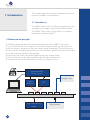
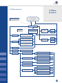
1.2 Measurement principle
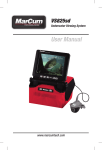
The following drawing shows the theoretical working function of the LAURA® Smart reader.
The strip is inserted into the urine sample then it has to be placed onto the strip holder tray. The
built-in strip detector recognizes the strip and starts the timing of incubation. The instrument moves
the strip under the measuring head and measures the reflectance. White LED makes the illumination
and a colour detector detects the reflected light.
The processing unit converts the reflected light intensity to the analytical value.
The result is presented on the display and printed by the built-in thermal printer.
The instrument moves out the strip holder tray and the user dispose the strip.
Microxcontroller
Processing unit
Reagent strip
Colour
detector
Strip holder driving
Motor
3
LED
Strip detector
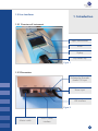
1.3 User Interfaces
1. Introduction
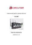
1.3.1 Overview of instrument
Paper release button
Printer
Display
Strip holder tray
Figure 1
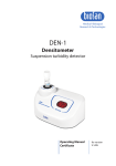
1.3.2 Connectors
Keyboard or Barcode
reader PS2 input
Power input
USB interface
Figure 2
Master switch
RS232 Serial
interface
4
1. Introduction
1.4 Icons and abbreviation
ID
- Patient identification code
(a figure or a text, max. 15 characters)
Seq.No
- Sequence number of the measurement
Sample
- Urine specimen to be measured
REM
- Remission value
BCR
- Barcode reader
Host
- Computer (Laboratory Information System)
Smart Timing® - Incubation timing method
5
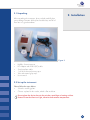
2.1 Unpacking
2. Installation
After unpacking the instrument, please check carefully that
your package contains all the parts listed below, and all of
them are in a good condition.
Figure 3
•
•
•
•
•
•
LAURA® Smart instrument
DC Adapter with 230 V (AC) cable
Serial interface cable
1 roll of the thermal printer paper
Tube with control grey strips
User manual
2.2 Set up the instrument
Please follow the steps below:
• Select the working place
• Choose a place for the reader, which is flat and clear
Do not place the device close to the window, centrifuge or heating surface.
Protect it from the direct sun light, vibration and extreme temperature.
6
2. Installation
• Connect the power and interfaces
Check if the master switch on the rear side is turned off!
Refer to Fig 2.
o Insert the serial cable and the keyboard or BCR to the
reader for the BCR use the PS2 input.
o Insert the adapter output plug to reader.
o Insert the adapter main cable into the net.
•
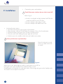
Inserting the printer paper
o Open the printer cover by pressing the release button!
o Place the paper roll into its holder and pull out approx. 10 cm of it in front direction.
o Check if the paper lies between the 2 metal ears of the printer.
o Close the cover while holding the paper tight with one hand.
o Push the cover in the middle or both sides until it clicks into its place.
Never push the cover asymmetrically!
ow the instrument is ready
N
to turn on; switch on the master switch!
Figure 4
After power on the display lights up and the reader carries out a Self Test.
During this test the optic and the built in calibration PAD is tested.
Completing the test successful, the reader prints out the OK message and goes into the Standby mode.
The reader is now ready for measurement.
7
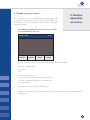
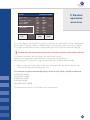
3.1 Ready to measure status
This is the status where the instrument after performing the Self
Test waits for user command. The instrument has a touch sensitive display. The user can control the instrument by pressing the
displayed buttons.
3. Routine
operation
overview
In the Ready to Measure status the following possibilities are available for the user:
INSERT STRIP!
12:23
Seq.No: 0001
PATIENT
SAMPLE
MENU
HOME
• Start a new measurement process, by placing a strip on the strip holder
• Enter patient information:
o Seq.No
o ID
•
Enter sample information:
o Select a sample colour from the predefined list
o Select a sample clarity from the predefined list
o Insert comment
• Enter the menu, by pressing the MENU icon.
• S
end the instrument to Stand by mode by pressing of button HOME or automatically after the
defined time.
8
3. Routine
operation
overview
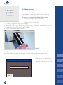
3.2 Measurement
The instrument LAURA® Smart begins the measurement automatically when a strip is placed on the strip holder tray.
To carry out a measurement do the following steps:
• Enter a new SeqNo or ID if necessary
• If you want to define the appearance of sample, select a
colour or clarity from the offer
• Deep the reagent strip into the urine sample
• Remove the excess urine from the strip (Push the edge of the strip to an absorbent paper, follow the Instruction of the strips PHAN® LAURA)
• Insert the strip into the strip holder tray
Figure 5
LAURA® Smart has a build in strip detector at the end of the insert area, under the tray. If the strip is
placed correctly this detector will recognize it and the incubation time countdown starts.
A progress bar displays the status:
MEASUREMENT
ESC
9
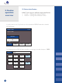
12:23
• After 55 sec the reader moves
the tray in, measures the strip,
displays and prints out the result.
RESULT:
Seq.No: 0023
ID:
03.10.2007 18:08
Colour: YELLOW
Clarity: CLEAR
COMMENTS:
ESC
DekaPHAN LAURA
BLD * LEU
BIL
UBG
KET
* GLU
PRO
pH
NIT
SG
SEND
NEG
75
NEG
NORM
NEG
50
NEG
6.5
NEG
1.025
Leu/ul
3. Routine
operation
overview
mg/dl
PRINT
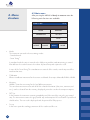
The result is displayed on the LCD. The positive parameters are marked with* and are displayed in
yellow colour. Pressing the PRINT or SEND button the result can be send or print any time again.
It is possible to add comment to the result by touching the screen inside the comment rectangle.
If a comment to this measurement already exists, the new comment will overwrite the old one!
The comment and all the other result parts are stored in the memory.
Placing a new strip into the holder will start the next measurement procedure.
After pushing the ESC button the, program jumps back to the Ready to Measure status.
• A
fter the strip was measured the reader moves the strip holder out, and the strip has to be
removed and disposed manually by the user.
The instrument recognizes automatically the type of the test strip, which is possible to measured:
DekaPHAN® LAURA
HeptaPHAN® LAURA
PentaPHAN® LAURA
DiaPHAN® LAURA
MicroalbuPHAN® LAURA
The instrument increases the Seq.No after every measurement.
10
3.3 Patient identification
3. Routine
operation
overview
LAURA® Smart supports 2 different sample identifications:
• Seq.No - working with Sequence Number
• Patient ID - working with Identification number
In order to enter a new Seq No the user has to touch the PATIENT button then select the SEQ.NO button.
INSERT STRIP!
12:23
Seq.No: 0001
SEQ.NO
ID
PATIENT
SAMPLE
MENU
HOME
The following numeric PAD will appear and the user can type a number between 1-9999.
Seq.No:
1234
1
2
3
4
5
6
7
8
9
0
11
ESC
OK
Selecting the ID button a similar edit field appears, where the
user can enter a max 15 characters long ID string. This ID could
also be entered with help of external keyboard or the barcode
reader in the Ready to Measure status as well.
ID:
3. Routine
operation
overview
ABCD1234abcd
_./
ABC
DEF
ESC
GHI
JKL
MNO
abc
PQR
TUV
WZXYZ
OK
-(#)
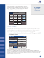
3.4 Colour and clarity
Before placing the strip to the way user can set the colour and clarity informations of the sample.
The colours and clarities are preddefined and can be modified by the user in the customisation
menu (see 4.6). There are four different colours and four different clarities available.
The colour and clarity information will be listed after pressing the following buttons SAMPLE
and COLOUR or CLARITY:
INSERT STRIP!
12:23
YELLOW
COMMENTS
RED
COLOUR
GREEN
CLARITY
BROWN
PATIENT
SAMPLE
MENU
HOME
Pressing the desired button will select the corresponding information.
It will appear on the display and will be added to the next measured sample. For deleting the
previously selected information, the user can go into the selection menu again but instead of selecting a value from the list the COLOUR or CLARITY button has to be pressed again. In this case the
program clears the previously set value.
12
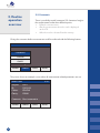
3.5 Comments
3. Routine
operation
overview
There is possibility to add comments (39 characters long) to
the measurements at the three different points:
• Before the measurement
• After the measurement when the result is displayed on the LCD
• When the result is selected from the memory
Giving the comments before measurement could be achieved with the following buttons:
INSERT STRIP!
12:23
COMMENTS
COLOUR
CLARITY
PATIENT
SAMPLE
MENU
HOME
This picture shows an example screen when all measurement related parameters are set:
INSERT STRIP!
Seq.No:
ID:
Colour:
Clarity:
12:23
0001
125X333
YELLOW
CLEAR
Comments: Short comment to …
PATIENT
13
SAMPLE
MENU
HOME
3.6 Cleaning
To keep the instrument clean and in the order to avoid crosscontamination, the strip holder tray must be cleaned. The strip
holder has to be clean periodically every day after the finishing
the work. The excess of urine has to be removed from the strip
before inserting it into the instrument.
For cleaning wipe off the tray use a soft textile or paper.
For cleaning with disinfections, use an alcohol disinfectant (max
85 %) such as ethanol, isopropanol, if necessary!
3. Routine
operation
overview
Never use acetone, petrol or other
aggressive solvents for the cleaning!
If necessary, the tray could be removed from
the reader by pulling it out manually. So it
could be cleaned or washed easier.
In this case pay attention not to damage or scratch or rub the white REF
plastic PAD!
This PAD could also be washed and wiped
with soft materials.
The strip holder is possible to remove
only it the instrument is switched off.
The instrument case and the touch screen
could also be wiped off with the above mentioned solvents.
The REF pad
WASTE DISPOSAL:
Used strip should be treated as potentially infectious and should be disposed in accordance with
local and national regulations relating to safe handling of such materials. Waste is to be recycled
or to be put to municipal waste.
14
4. Menu
structure
LAURA® Smart has a clear, well organized menu structure. The
user is guided trough the menu by the LCD. The menu functions
are represented by buttons or list controls.
Pressing the touch screen can activate the desired function.
The pressed buttons are highlighted by blue colour.
If no button is pressed TBD minute long the program jumps
back to Stand by status.
In this status the reader pulls in the strip holder tray, the buttons
disappear from the screen and the actual time is displayed.
T o leave this status and enter back to Ready to measure status
the screen has to be touched anywhere.
15
4.1 Menu overview
4. Menu
structure
Time out or pressing HOME
Stand by status or power ON
Ready to measure
Measurement
Strip
inserted
Mode
Display Result
ID
Seq.No
Sample
information
Comment
Colour
Clarity
Timing: Standard / Smart
Filter: All / ID / Seq.No /
Positive / Not printed
Memory
Patient
information
Day: All / Today / Date
Action: Display / Print /
Send / Delete
QC Test
Calibration
Setup
Calibration code/Default
Strip Parameter
Order: Deafult / New
Unit: CONV / SI / ARB
User Interface
Printer: On / Off
Interface: On / Off
Sound: On / Off
Language
EN, DE, FR, IT, PL, CZ, HU, RU
Date / Time
Customisation
Logo: On / Off
Header text: 1 / 2
Greetings text: 1 / 2
Colour text: 1 / 2 / 3 / 4
Clarity text: 1 / 2 / 3 / 4
16
4. Menu
structure
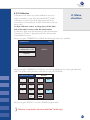
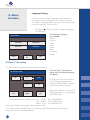
4.2 Main menu
After pressing the MENU in Ready to measure status the
following main functions are available:
INSERT STRIP!
12:23
MODE
MEMORY
CALIBRATION
QC TEST
SETUP
PATIENT
SAMPLE
MENU
HOME
•
Mode
The instrument can work in the two timing modes:
- Standard mode
- Smart Timing®
In standard mode the strip is inserted to the holder tray and the incubation timing is started.
After 60 sec the reader measures the colour of placed strip and reports the result.
In case of the Smart Timing® the incubation runs outside of the reader, max 4 strips could be
incubated at once.
• Calibration
Allows to calibrate instruments for the current used batch of test strips MicroalbuPHAN® LAURA.
• Memory
LAURA® Smart has a memory for the last 360 measurements.
The stored measurement results with all of their related information (date, time, comment, colour..), can be selected from the memory, displayed, printed or send to the computer anytime.
• QC Test
In this function the instrument measuring capability could be tested, by using the grey control
strip. The instrument measures the grey control strip and compares the result with the predefined
should values. The test result is displayed and also printed for QA purpose.
• Set up
In this menu point the working parameters of the reader could be set.
17
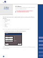
4.2.1 Timing modes
LAURA® Smart has two different timing modes:
Standard mode and Smart Timing®
4. Menu
structure
Standard mode
It is a linear workflow as is described in the routine
measurement chapter.
Working in this mode only 1 strip/minute measuring speed
could be achieved.
Smart Timing®
It is used to speed up the measurement with the LAURA® Smart.
In this working mode the throughput is increased due to incubating of the strips are outside of the reader.
The user places the measured strips outside of the reader and when the incubation time elapses, the
strip will be inserted into the reader only for the time of the measurement.
To support this process is offered an incubation plate with the four slots and the reader gives four
corresponding software timers.
The general workflow for using of the Smart Timing® mode is follows:
o Whenever a timer is available (green) insert a strip to the urine sample.
o Place the strip on the incubation plate, to the corresponding slot, and start the timer/the corresponding progress bar by pushing it. The green progress bar changes the colour to the yellow.
o Whenever a timer runs down, it beeps and the colour turns from yellow to red.
o Pick up the corresponding strip from the incubation plate and place it to the instruments strip
holder tray.
The following pictures help to understand the procedure.
18
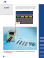
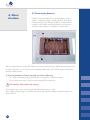
4. Menu
structure
The position 1 is available for the new strip. The incubation has
finished on the position 2 and the strip is inserted on the strip
holder. The incubations run on the positions 3 and 4 with the
strips/samples with Seq.num. 12 and 13.
MEASUREMENT
1
12:23
2
3
4
0012
0013
ESC
Keep the incubation plate clean, you prevent the possibility of cross-contamination among
the individual samples.
19
4.2.2 Calibration
4. Menu
Calibration mode allows to perform calibration on the currently used batches of test strips MicroalbuPHAN® LAURA.
structure
Calibration is performed for both diagnostic pads for the
determination of microalbumin and for determination of creatinine in urine.
Six-digit calibration code is an integral part of the label
and on the label is always under the batch number.
The first three digits are associated with a pad for determination
of creatinine, the other 3 digit with pad for the determination
of microalbumin in urine.
After pressing the CALIBRATION in MENU the following functions are available:
CALIBRATION
12:23
CALIBRATION CODE
435820
DEFAULT
After pressing the CALIBRATION CODE the numeric keypad appears for entering of calibration
code. The update setting becomes valid after pressing the OK button.
435820
CALIBRATION CODE
1
2
3
4
5
6
7
8
9
ESC
OK
0
After pressing the DEFAULT is set value 435820 (original value).
Calibration is intended for strips MicroalbuPHAN® LAURA only!
20
4.2.3 Memory
4. Menu
structure
The reader has a non-volatile memory, which automatically
stores the last 360 measurements.
The oldest result will be overwritten by the new
measurement without any warning.
When the actual measurement is ready the reader stores the result along with the following
parameters:
• Result of the strip
• Type of the strip
• Seq.No
• ID
• Date and time
• Colour
• Clarity
• Comment
The user can reach the memory from the Menu by selecting the Memory button.
For administration the Memory the following display appears:
MEMORY
FILTER
ALL
DAY
ALL
ACTION
ESC
DISPLAY
START
FILTER and DAY button serve to set the selection parameters, after then the START button activates
the selected action.
21
The desired measurement can be selected
in the following way:
4. Menu
structure
•
Select the FILTER criterion:
o All
- all stored result
o ID
- enter the desired ID
o Seq.No - enter the desired Seq.No
o Positive
- where at least 1 value was positive
o Not printed- results that where not printed yet
•
Select the DAY of the measurement:
o All
- regardless of date
o Today
- searching only among the today measured result
o Specific date- select the desired day
(The program offers only those days where there are results in memory.)
•
Choose an ACTION, what should happen with the selected results:
o Display - the selected measurements will be displayed
o Print
- the selected measurements will be printed
o Send - results will be sent to HOST, RS232 and USB
o Delete
- the measurements correspond with the selection criterion are deleted
When all three above mentioned parameters (Filter, Day and Action) have been defined, the
process can be activated by pressing the START button.
In case of DISPLAY was selected the found results are displayed in following form:
MEMORY: 1 / 3
DekaPHAN LAURA
Seq.No: 0023
BLD
ID:
*LEU
03.10.2008
18:08
Colour: YELLOW
UBG
Clarity: CLEAR
KET
*GLU
COMMENTS:
pH
NIT
SG
ESC
NEG
75
BIL
NORM
NEG
50
PRO
6.5
NEG
1.025
Leu/ul
NEG
mg/dl
NEG
PRINT
The latest measurement in the list will be displayed at first.
With help of the
buttons the user can step forward or backward in the list.
The actually displayed result could be printed and the new comment could be attached.
22
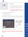
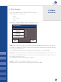
4.2.4 QC Test
4. Menu
structure
The purpose of this test measurement is to verify that the optical
measuring capability of the instrument works properly. Perform
this test once a week, or if you receive suspicious result in
normal use. For testing the instrument the grey control strips are
provided in the LAURA® Smart package.
Clean carefully the strip holder before using of QC
Test. You prevent the degradation of the grey control
strip with the rest of urine.
Take out one from the tube and follow the steps below:
• Select the QC Test button
• Place a grey strip on the strip holder tray
• The reader starts the measurement
• Wait for the measurement is complete.
After measurement the reader compares the obtained remission values to the predefined ranges,
stored in the instrument, in every greyscale and wavelength. Then displays and prints out the result.
When the measured values are in harmony with the predefined values the result of QC Test is OK.
The picture of the display after QC Test is following:
TEST MEASUREMENTS
1:
2:
3:
690
350
145
12:23
Print out the result of measurement:
700
354
130
Test: OK
ESC
Keep the print out for QC reference.
If the test fails, Test Error will be reported and the wrong result is displayed in red. In this case repeat the
test with another check strip. If it gives error again call the service.
Keep the grey strips always in its tube, do not touch the surfaces by hand, and handle
them with care. The strips are intended for repeated using. Refer to the label of the grey
strip tube!
23
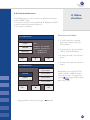
4.2.5 Settings
Under this menu point the instrument working parameters
could be set.
4. Menu
structure
The available settings are displayed
in the following format:
SETUP INSTRUMENT
PARAMETER
DATE / TIME
USER INT.
CUSTOMISATION
LANGUAGE
ESC
The several working parameters are organized in the following way:
• Parameter – strip and measurement related parameters could be set here, as:
ORDER of parameter at printing
UNIT of parameters
•
User interface – turning ON/OFF the following user interfaces:
PRINTER
INTERFACE (HOST)
SOUND
•
Language– selecting the language from the 8 defined languages:
EN – English
DE – German
FR – French
IT – Italian
CZ – Czech
PL – Polish
HU – Hungarian
RU – Russian
• Date / Time – set the date and time and the format of date
• Customisation– customizing the header text and logo, defining the colour and clarity texts
24
4. Menu
structure
4.3 Parameter Settings
This menu point is divided into two submenus:
• Printing order
• Unit settings
4.3.1 Printing order
The parameter printing order can be set in the following
menu point:
MEASUREMENT PARAMETERS
ORDER
DEFAULT
NEW
ESC
Pressing the DEFAULT button the printing order will correspond to the Parameter order of the strip
DekaPHAN® LAURA.
The instrument allows changing this order as the user like. In this case the NEW menu point should
be used. The program offers all the parameters and they should be touched after each other in the
desired order.
25
4.3.2 Unit settings
4. Menu
structure
Unit can be selected with help of the
following menu point:
MEASUREMENT PARAMETERS
ALL: CONV
UNIT
PAD TO PAD
ESC
OK
CONV, SI, and ARB
The ALL: button set the selected unit for all the 10 parameters.
If the user would like to set the unit individually for the parameters then the PAD TO PAD button can
be used. In this case the parameters are displayed in the header of the LCD and the desired unit
can be set individually.
BLD
CONV
CONV + ARB
SI
SI + ARB
ARB
ESC
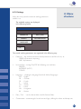
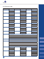
The following table summarizes the possible reported values in the entire of three units:
26
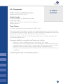
4.3.3 Parameter table
Parameter
BLD
LEU
BIL
UBG
KET
GLU
PRO
values
NEG
10
50
250
NEG
25
75
500
NEG
1
3
6
NORM
1
3
6
12
NEG
5,2
16
52
156
NORM
50
100
300
1000
NEG
30
100
500
CONV
unit
Ery/µl
Leu/µl
mg/dl
mg/dl
mg/dl
mg/dl
mg/dl
SI
values
NEG
10
50
250
NEG
25
75
500
NEG
17
51
103
NORM
17
51
102
203
NEG
0,5
1,5
5
15
NORM
2,8
5,5
17
55
NEG
0,3
1
5
pH
unit
Ery/µl
Leu/µl
µmol/l
µmol/l
mmol/l
mmol/l
g/l
5
6
6,5
7
8
9
NEG
POS
NIT
SG
1,000
1,005
1,010
1,015
1,020
1,025
1,030
CRE
MA
27
0,1
0,25
1
2
>3
10
30
80
150
300
1000
5000
g/l
mg/l
0,9
2,2
8,8
17,7
> 26,5
0,01
0,03
0,08
0,15
0,3
1
5
mmol/l
g/l
ARB
values
NEG
1+
2+
3+
NEG
1+
2+
3+
NEG
1+
2+
3+
NORM
1+
2+
3+
4+
NEG
±
1+
2+
3+
NORM
1+
2+
3+
4+
NEG
1+
2+
3+
4.4 User Interface
In this menu point the built in interfaces could be switched
ON or OFF. These interfaces are:
4. Menu
structure
- Printer
- Serial interface
- Sound
The factory setting for LAURA® Smart is all interfaces: ON.
USER INTERFACE
PRINTER
ON
INTERFACE
ON
SOUND
ON
ESC
OK
Printer ON /OFF means, that the results will be printed automatically after measurement, or not.
It is possible to switch off this feature, in this case the instrument will measure the strip and store it in
the memory, but it won’t print it.
The result can be printed at any time from the memory or when the result is displayed.
Interface ON /OFF means that the results will be send to Host automatically after measurement, or not.
It is possible to switch off this feature, in this case the instrument will measure the strip and store it in
the memory, but it won’t send it.
The result can be sent at any time from the memory.
Sound ON/OFF turns the button feedback beep on or off.
Warning beeps are always ON, this setting has no influence to them.
28
Language Setting
4. Menu
structure
Here the user can select the language of the instrument.
Pressing the corresponding button can make the selection.
The actual set language button is pressed. OK button must be
pressed to make the selection valid.
Pressing the button the next four available languages
are displayed.
LANGUAGE
ENGLISH
FRANCAIS
DEUTSCH
ITALIANO
ESC
The following languages
are available:
English
German
French
Italian
Czech
Polish
Hungarian
Russian
OK
4.5 Date / Time setting
The Time and the Date format can be set in this menu point.
Select the Date / Time button in
settings menu, the following display
will appear:
SET DATE & TIME
03
ESC
11
2007
11
49
FORM
OK
To change the date or time values
push the corresponding button!
A numeric PAD will appear and the
desired value can be entered.
When date and time are correct the
DATE format can be set, by pressing
the FORM button.
The following formats could be used: Year – Month – Day YYYY-MM-DD
Day – Month – Year DD-MM-YYYY
Month – Day – Year MM-DD-YYYY
Pressing the OK button the actual settings became valid.
The real time clock in LAURA® Smart is running from a built in lithium battery. This battery is
independent on the removable batteries.
29
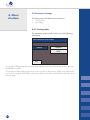
4.6 Customisation menu
Customisation menu serves to enter user defined texts into the
reader LAURA® Smart.
The text lines could be entered with help of alphanumeric PAD
or with a connected external keyboard:
These texts are as follows:
These texts are as follows:
CUSTOMISATION
LOGO
HEADER
GREETING
ON
Header 1. line 123456
Header 2. line labor na
1. greetings line
2. greetings line
ESC
OK
• 2 result header lines, appear
with each result print out, max
24 characters
• 2 greeting lines, are printed after
self test, max 24 characters
• 4 clarity text each, max 10 characters
• 4 colour text each, max 10 characters
CUSTOMISATION
Colour text 1
COLOUR
Colour text 2
CLARITY
Colour text 3
Colour text 4
ESC
4. Menu
structure
Paging could be done by pressing the
Beyond these, the Logo ON/OFF
switch could be reached from this
menu point. In case of Logo ON is
set, the
logo will be printed
with every results.
OK
buttons.
30
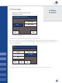
4. Menu
structure
4.7 Powering by batteries
LAURA® Smart could also be used with batteries power
supply. The battery holder is locating at the bottom of the
instrument. 6 pcs 1.5 V AA type batteries or accumulators
could be used. While inserting the batteries, please pay
attention to the polarity. It is indicated on the holder.
When using the batteries type LRG, 200 measurements with printing or 240 without printing could
be carried out with one set. The instrument displays a BAT icon on the LCD that gives information
about the battery status.
To increase the batteries lifetime generally consider the following:
• Turn off the automatic printing and print the result only if it is really necessary!
• If the measurement series has been done switch off the instrument.
The Stand by status needs also energy!
The instrument gives a beep warning in Stand by when battery is used.
If the adapter power plug is inserted the instrument will work from adapter and the batteries are
disconnected.
31
LAURA® Smart is a high sensitive and accurate optical measu
ring instrument. All optical components, and REF PAD are
adjusted with special tools during manufacturing.
5. Service
information
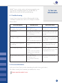
5.1 Trouble-shooting
In case of any error, please refer the following table. It helps
to identify the possible cause of the error and gives instruction
how to solve it.
Error description
Possible cause
Corrective action
The reader cannot be switched on.
The display remains dark.
Power supply is not
connected or wrong type.
Check the power supply and the
connections.
Self test failed.
Strip holder tray is missing or the
REF PAD dirty movement of the
tray is obstructing.
Check the strip holder tray it must
be clean and easy to move also
by hand.
The reader doesn’t print, or the
printing is not visible.
Paper cover is not closed.
Wrong paper is in (not thermal
paper).
Paper is inserted with wrong side up.
Check the printer visually, for any
damage or jam. Insert the right
type of paper correctly. Close the
printer cover.
The reader won’t recognize the
inserted strip.
The strip holder tray is in wrong
position.
Check if the round whole of the
tray is exactly above the strip
detector.
Host communication failed.
Serial cable is not attached or
wrong.
Interface mode is turned OFF, or
parameter doesn’t match with
HOST settings.
Check the cable!
Check that interface mode is ON
and parameters are correct.
Reader displays Measurement
Error.
Strip is placed wrong.
Wrong strip is used.
Dry or not fully inserted strip
is used.
Repeat the measurement with
correct strip.
5.2 Service information
In the case of error, first try to solve it according the trouble-shoot guide above.
If the failure remains, please contact your distributor for service.
Never open the reader’s case.
32
5. Service
information
5.3 Safety information
LAURA® Smart complies the with EMC directive 89/336/EEC
and low voltage directive 73/23/EEC.
LAURA® Smart instrument in combination with PHAN® LAURA test
strips complies with the requirements of IVD directive 98/79/EC.
5.4 Producer
Producer of the system LAURA® Smart and diagnostic strips PHAN® LAURA:
Erba Lachema s.r.o.
Karásek 1d, 621 33 Brno
Czech Republic
5.5 Ordering information
LAURA® Smart reader DekaPHAN® LAURA
HeptaPHAN® LAURA
PentaPHAN® LAURA
DiaPHAN® LAURA
MicroalbuPHAN® LAURA
-
-
-
-
-
-
cat. number:
50003508
10008297
10008298
10010239
10010238
10010262
Spare parts:
Strip holder tray for LAURA® Smart
Power supply for LAURA® Smart
Interface cable for LAURA® Smart
The grey control strips for LAURA® Smart
-
-
-
-
50003510
50003511
50003512
50003513
5.6 Guarantee conditions
The producer Erba Lachema s.r.o. guarantees the reader LAURA® Smart for 12 months after installation. The free service isn’t guarantea for spare parts from the list (see 5.5).
33
6. Technical
parameters
General
Dimension
Weight
Power source
Power consumption
max / standby
Battery
Battery life type LRG
230×127×110 mm
0.7 kg without batteries
External adapter
7.5 V DC / 6 A
90–230 V/ 50–60 Hz
20 W / 6 W
6×1.5 V AA
200 measurements with printing or 240
without printing
Measurement
Method
Throughput
Wavelength
AD resolution
Reflection photometry
max. 240 strips/hour
470, 540, 650 nm
10 bit
User Interface
Printer
LCD
58 mm graphical thermal printer, 24 char/line
320×240 colour TFT
Memory
Capacity
RTC
360 complete measurement results
Lithium battery kept real time clock
Interfaces
Host interface
RS232 Serial interface, 19 200 Bd 8N1
USB interface
Wedge type BCR with standard PS2
interface
BCR / PC AT keyboard
Recommended
operating
environment
Temperature
Humidity
Place
15–35 °C
Optimal range 20–25 °C
20–80 %
Horizontal surface
No shock or vibration
Not direct Sun shine
Storing / transport
Temperature
Humidity
-20–60 °C
20–90 %
34
The LAURA® Smart has an RS232 interface to HOST computer. If the communication is enabled (Interface: ON) the reader
sends out the result immediately after measurement. Stored
measurements can also be sent at any time from the memory.
7. Serial interface
protocol
The hardware parameters of the RS232 port are:
Baud rate: 19 200 Bd
Bit length
8
Parity:
No
Stop bit:
1
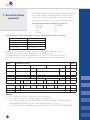
The interface has a DB9 mother type connector with the following PIN connection:
PIN number
Connected
2
TxD
3
RxD
5
GND
1, 4, 6, 7, 8, 9
- not connected
If USB host is connected, the reader sends the data trough the USB port as well.
The format of the data stream is identical to the serial (RS232) case.
The communication is unidirectional LAURA® Smart -> HOST, and is in ASCII text form.
The reader sends 1 result in 1 package. Every package has the same format, which is:
Name of
field
Frame start
Seq.No line
ID line
COLOR
CLARITY
Date line
1st. result line
10th. result line
Comment line
Frame end
CR, LF
# of
bytes
26
CR, LF
26
CR, LF
26
CR.LF
CR LF
CR, LF
CR, LF
21
21
26
26
Characters sent out
STX
Strip name
“Seq.No:”
7 char
“Pat.ID:”
7char
„COLOR:“
„CLARITY:“
YYYY.MM.DD
‘*’ or SP 3char par.
SP
name
‘*’ or
SP
{
ETX
SP
SP
SP
3×SP
SP
SP
9 space
4 char long Seq number, right justified,
filled with 0
14 char long ID
Color text 10 char
Clarity text 10 char
6×SP
HH:MM
5char result SP 6char unit
Conv or SI
3char par.
SP
5char result
name
Conv or SI
80 char long comment or space
SP
6char unit
SP
SP
2×SP
3×SP
5char ARB
result
5char ARB
result
CR, LF
26
}
82
1
Where:
• STX = 0×02, ETX= 0×03, CR=0×0d, LF=0×0a, SP=0×20
• The parameter order is the default regardless of printing order.
• In case of shorter strip (HeptaPHAN® LAURA, PentaPHAN® LAURA, DiaPHAN® LAURA,
MicroalbuPHAN® LAURA) only the measured parameter lines are sent
• The result and the unit is depending on the selected unit (SETTINGS/STRIP/PARAMETER)
35
8. Short
Instructions
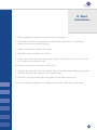
1. Check carefully if the instrument is complete and not damaged.
2. Connect the instrument to the plug with the relevant cable; check if there is a connection
between the instrument and external plug.
3. Switch on the instrument with the main switch.
4. Wait till the instrument performs the self-test.
5. Set the mode of the results (direct printing after analysis, printing after measurement of all samples, sending to the external net etc.).
6. Start the measurement in the mode Seq.No or ID.
7. C
omplete the measurements of urine samples; follow all recommendations during the operation,
which are included in the instruction of the diagnostic strips.
8. Perform the everyday cleaning after having finished your daily measurements.
9. Leave the instrument switched on in Standby mode or switch it off using the main switch.
36
9. Index
37
Adapter
6, 33
Battery
31, 35
Clarity
8, 12, 21, 30
Cleaning
14
Colour
8, 12, 21, 30
Comments
8, 10, 13, 22
Customisation
12, 24, 30
Date
17, 21, 22, 24, 29
Display
4, 8, 9, 13, 15, 21, 22, 24, 25
ID
5, 8, 9, 11, 12, 21, 22, 37
Installation
6, 7
Interface
6, 7, 24, 28, 32, 34, 35
Languages
24, 29
Logo
30
Measurement
3, 9, 13, 23, 32, 34
Memory
17, 18, 21, 34
Menu/MENU
8, 15, 16, 17, 18
Paper
6, 7
Parameter
26, 27
Principle of measurement
3
Printer
4, 24, 28, 34
QC Test
17, 23
Sample
5, 12, 36
Seq.n.
5, 8, 9, 11, 18, 21, 22, 36
Set up
6, 17, 22, 24, 26
Smart Timing®
5, 17, 18, 19
Sound
24, 28, 29
Standby mode
7, 31
Strip
3, 6, 8, 9, 10, 14, 21, 22, 23, 26, 29, 33
Strip holder
4, 10, 14, 23, 33
Technical parameters
35
Time
17, 18, 21, 24, 29
Units
24, 25, 26, 27
Unpacking
6
User interface
28