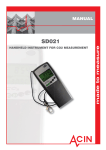
1
User Manual
SenseAir ®Alarm
Portable carbon dioxide sensor and alarm unit
for personal safety
with Real Time Clock
SenseAir Alarm
Included
General
The SenseAir portable sensor is a lightweight CO2 instrument with a digital display designed
to measure the carbon dioxide concentration in ambient air. Built-in data logging and alarm
functions with both audible alarm and LEDs make this portable pocket size instrument perfect
for personal safety applications. The display shows the current carbon dioxide concentration
and the past 8 hours TWA (Time Weighted Average) value. The gold-plated carbon dioxide
sensor measures the carbon dioxide concentration in %VOL. State-of-the-art non-dispersive
infrared technology and automatic calibration functions have resulted in great reliability,
accuracy and long-term stability of operation. The battery capacity is more than 12 hours.
EM_SenseAir_Alarm_RTC_Oct'05
Page 1 of 12
Function Description
Air outlet
Air inlet
The instrument is durable, but for extra safety the
instrument shall be secured by the safety strap on the top.
The measuring sensor is inside the unit. Several openings
in the housing make the air circulate through the unit.
These openings must be kept open!
Please note! Whenever you go from a cold environment
to a warm environment there is a risk of condensation
(anyone with glasses has noticed it). To avoid that this
influences the accuracy of the instrument it is important
to allow it to adjust to the environment for a few minutes
before usage
Figure 1. The flow through the unit.
The display shows the instantaneous CO2 value and the TWA-value. The instantaneous CO2
value is also easy overviewed with the front panel LEDs. When the CO2 concentration
reaches the lowest alarm level the second yellow LED is lit and an intermitted audio alarm is
triggered. If the concentration continues to rise the red LED is lit as the second alarm level is
reached and a continuous audio alarm is triggered.
On/OFF/Function Button
Push the button for ten seconds
to turn ON the sensor
Status Indicator
CO2 Concentration in % VOL
TWA value
in % VOL CO2
Battery Indicator
Red LED: Main Alarm
3,0 % VOL CO2
2nd Yellow LED: Pre Alarm
1,5 % VOL CO2
1st Green LED: Always activated
in On or Sleep Mode
2nd Green LED:
0,1 %VOL CO2
1st Yellow LED:
0,5 %VOL CO2
Figure 2. Front Panel
Note: If the status indicator is shown the readings are not reliable! The actions
to take are then always first to charge the battery, second to recalibrate the CO2
sensor zero point (put the unit in CALb Mode). If still the status indicator is
shown after these two actions, please contact your dealer!
EM_SenseAir_Alarm_RTC_Oct'05
Page 2 of 12
Default Push Button Functions
On Mode
• Normal operation
• Alarm enabled
• TWA logger active
• ABC algorithm disabled
Push the button until the display shows "tESt" (for ten seconds),
then release the button. The unit will then perform a full self-
test sequence showing the LEDs and buzzer response for
the alarm setpoints. After the test the unit is in On Mode.
Off Mode
Explanation
Push Button
"tESt"
Release Button
On Mode
Power Off
•
TWA logger data will be
reset.
From On Mode, push the button until all front panel leds are
turned off. While pushing the button the unit will pass through
the mode "CALb". If you accidentally release the button too
early, just push the button once to reach On Mode and try again.
On Mode
"CALb"
Off Mode
CALb Mode
• TWA logger on hold
• ABC algorithm enabled
From On Mode, push the button until the display shows CALb,
then release the button. This will activate the Automatic Baseline
Calibration ABC that requires 5 hours to complete one calibration
cycle. The instrument continues to execute calibrations every
four hours as long as it is left in CALb mode. Intended for
overnight charging in fresh air, with minor calibration adjustment
automatically performed.
To get back to On Mode, just push the button once.
On Mode
" CALb"
Back light & Application
Function Execution.
Acknowledge Alarm
Can be turned on temporary by pushing the button. The
backlight is turned off after 8-16 seconds. Application function for
"standard" default setting is just backlight.
In alarm and pre alarm states, pushing the button resets the
sounding buzzer for 5 minutes at a time.
EM_SenseAir_Alarm_RTC_Oct'05
Page 3 of 12
Instantaneous CO2 Concentration
The instantaneous CO2 concentration is shown in the upper part of the display and should
never exceed recommended short term exposure limit values. The instantaneous CO2
concentration is also indicated with the five LEDs below the display. Immediately leave the
area if the second yellow LED is lit and the buzzer sounds!
Alarm functions (factory settings):
LED
Green 1: always lit when the unit is on
Green 2: >0,1 % VOL (Recommended indoor max CO2 concentration level)
Yellow 1: >0,5 % VOL
Yellow 2: >1,5 % VOL, Buzzer (bip-bip-bip-…), pre alarm.
Red: >3,0 % VOL, Buzzer (biiiiiiiiiiii….), main alarm.
When the CO2 concentration exceeds 1,5 % VOL the second yellow LED is lit (pre alarm) and
the buzzer beeps intermittent. If the CO2 concentration rises above 3,0 % VOL the red LED is
lit and the buzzer sounds continuously. By pushing the button (alarm acknowledgement) the
buzzer temporarily will be turned off. The backlight is automatically turned on at pre and
main alarm and turned off 8-16 seconds after alarm acknowledgement. If the alarm condition
remains 5 minutes from alarm acknowledgement the buzzer becomes actuated again. When
the alarm condition has vanished the SenseAir Alarm returns to normal operation with the
buzzer silenced (- if not acknowledged the backlight will remain on).
The TWA Value
8 hours TWA (Time Weighted Average) value represents the average carbon dioxide level
exposure during a working day. In most European countries the CO2 hygienic limit value (8
hours/day or 40 hours/week) is set to 0,5 % VOL (5000 ppm). It is considered unhealthy longterm to be exposed to more than this value during an 8-hour working day.
The TWA value is shown in the lower part of the display. At power on the TWA-value starts
from 0,04% CO2 and accumulates current carbon dioxide levels averaged over time. Data
acquisition is done every 4th minute for the passed 4 minutes average exposure.
During continous operation the TWA value displayed by the SenseAir Alarm unit is an
average value of the latest 8 hours data recorded. To reset TWA, just switch the unit into Off
Mode and back on (without any battery charger connected). Senseair then starts up with the
default value 0,04 % VOL CO2.
In CALb, the current TWA-value is kept on hold. This is useful when you want to take a
pause in measuring, for example, if you are doing a worksite investigation and have to leave
the area for some time. When the unit is switched back into On Mode it will resume the
started TWA recording period.
Switching the unit into OFF Mode, with the battery charger connected until switched back
into ON Mode again, will also pause and resume the TWA calculations.
For the records, it is possible to download to a PC all logged data for the last 8 hours TWA
period. A special communication cable is required (included), plus the free software UIP-P
EM_SenseAir_Alarm_RTC_Oct'05
Page 4 of 12
(can be downloaded from www.senseair.com). This connection can be done in OFF Mode
during battery charging, as well as during normal operation in ON or CALb Modes, with or
without any battery charger connected.
Charging of the Battery
Charging of the battery can be done with the unit in Off-, CALb- or On Mode. The electronic
circuitry gets activated by charging also in Off Mode, but will return to initial off state when
disconnected. When the DC- adapter is connected the charging of the battery is indicated by
the rolling battery icon. When the battery is fully charged the battery icon is lit continuously.
The SenseAir unit automatically stops charging when the battery is fully charged.
The charging time for a completely discharged battery is 4±1 hours and the battery capacity is
more than 12 hours of operation.
DC-adapter
Calibration Gas Inlet
Communication Port
New sensors with A232R have red connection parts
and a red spot on the cable
Old sensors are the same colour as the housing
Figure 3. Connections
Self Diagnostics and Calibration
The SenseAir is basically maintenance free. The system contains a complete self-diagnostic
routine, which is executed automatically every time the power is turned on. The unit will then
perform a full self-test sequence showing the LEDs and buzzer response for the alarm
setpoints. SenseAir is working with continuous self-diagnostics during operation (On Mode).
If any error is detected the Status Indicator Segment will be lit.
The sensor has an automatic calibration function to secure long-term accuracy. It's called
Automatic Baseline Calibration (ABC), implemented to eliminate any zero point drift of the
infrared sensor. ABC calibration cycles are performed in 4 hours intervals. During some
minutes of that time fresh air (CO2 concentration between 380-420 ppm) has to be present.
ABC function is only active in "CALb Mode" (after one hour delay) and requires 1 to 5 hours
to perform one calibration adjustment. Each such adjustment is limited to a fine-tuning of
0,01% CO2. Several consecutive adjustments might be performed, if required, for each
additional 4 hours period stay in “CALb Mode”.
The CALb Mode is intended for overnight charging in an area with good ventilation, or close
to the fresh air inlet.
EM_SenseAir_Alarm_RTC_Oct'05
Page 5 of 12
User Interface Program UIP-P
Software Program
UIP-P is a PC software tool that can be free downloaded from http://www.senseair.com/.
Together with the included cable the SenseAir can be connected to a computer to:
1.
2.
3.
4.
5.
6.
Load measured samples from SenseAir Alarm into the computer.
Configure the trigger levels for the five LEDs.
Configure the alarm levels for the buzzer.
Customize display. Which parameters shall be visible for the user?
Save and load application and customized files.
Make CO2 sensor calibrations.
Sensors with serial number 18602163 or higher, which have a red connection part, must be
used together with a cable with red spot.
This computer communication can be done in all modes; on, off or CALb, with or without the
charger connected.
The File menu has sub menus; Load settings from file, Save settings to file, Load backup file,
Save backup file, Close.
Load settings from file
Save settings to file
Loads setting from a set file eg an application file.
Saves settings in a set file
The Sensor menu has sub menus; Read from sensor, Send to sensor, Calibrate.
Read from sensor
Use this button to load settings and samples from the sensor.
Send to sensor
Sends settings to the sensor.
The Help menu has sub menus; About (version number), Help
UIP-P has six folders
The folder General shows sensor data and current reading of CO2 and CO2 TWA.
The folder LED shows the selected values to turn on the LEDs. The values can be to desired
values. Enter the new values into the sensor by pushing the button Send to sensor.
Figure 4. The folder General in UIP-P shows
shows the sensor data and current readings
Figure 5. The folder LEDs in UIP-P shows the
concentrations to turn on the LEDs
EM_SenseAir_Alarm_RTC_Oct'05
Page 6 of 12
In the folder Display the two rows on the display are shown. Default is CO2 concentration
measured in % and the TWA value in %. If the default is not used the display may show other
parameters. Send the new settings to the sensor by pushing the button Send to sensor.
In the folder Buzzer the alarm limits are set.
Figure 6. The folder Display in UIP-P shows what Figure 7.In the folder Buzzer in UIP-P the alarm
Is shown on the display.
limits are set
In the folder CO2 History the sampled CO2 readings are shown. Readings can be saved in
files. See Sampling of CO2 readings. By pushing “Get data” a simple graph with data up to
the time the sampling counter is shown. Push the button ”Reset CO2 history” to clear the
sampled readings.
Figure 8. In the folder CO2 History in UIP-P the sampled readings are shown.
EM_SenseAir_Alarm_RTC_Oct'05
Page 7 of 12
In folder Logger the readings in real time are shown. Move the mouse over it and a box will
appear showing time and CO2 value as the pointer is moved on the X-axis. The desired
sampling interval can be set here. Push the button ”Reset logger” to clear the logger.
Figure 9. In the folder Logger in UIP-P the sampled readings are shown in real time.
Sampling CO2 readings
SenseAir Alarm continuously samples CO2 readings. The internal sample counter is active in
On mode and is reset if the sensor is turned off without the charger connected. All readings
sampled when the counter was active can be seen in User Interface Program UIP-P. All data
from UIP-P can be saved in a text file or an excel file for storage or further data processing.
Up to 580 readings can be stored in a FIFO memory (“first in first out”). If the sensor is in On
mode during longer time older data can be overwritten so that the latest de 580 samples are
stored. The sampling interval can be selected in folder ”Logger”. Preset value is 5 minutes /
two days measuring time. By selecting different sampling intervals the measuring time can be
longer or shorter. If the sampling interval has been changed the sensor must be restarted
after the change with the charger NOT connected. If the sensor is not restarted the
graph will not show the right data.
The sample counter is always active in On mode. Push the buttons ”Reset logger” and ”Reset
CO2 history” to clear the sample counter. In CALb mode the sampling is interrupted and
continues when the sensor is in On mode. This is useful if you want to take a break in the
measurements. If the sensor is turned Off with the charger connected the sampling is
interrupted and continues when the sensor is turned on.
It is recommended to start a sampling period with a fully charged battery and to try to avoid
charging during the sampling time. If the charger is connected to the sensor the battery will be
charged when needed. If the voltage falls below a certain level the sensor is automatically
turned off and the sample counter is cleared (the same if the sensor is turned off without the
charger connected). Old data remain until they are overwritten.
EM_SenseAir_Alarm_RTC_Oct'05
Page 8 of 12
Tips before a measurement
• If possibly do the measurements without the charger connected.
• Start the measurement with a fully charged battery.
• Select a sampling interval without overwriting samples.
Note!
• If the sensor is turned off without the charger connected the sample counter is
cleared. New measurements start from zero.
• If the voltage sinks below a certain level the sensor is automatically turned off
and the sample counter cleared. If the sensor is turned off with the charger
connected a break is done in the sampling. When restarted the sampling
continues where it was interrupted.
• If the sensor is in CALb mode only a break is done in the sampling. When
restarted the sampling continues where it was interrupted.
• If the sensor is cleared the sampled values remain until they are overwritten.
Calibration with computer and UIP-P
Back ground calibration Place the sensor in fresh outdoor air. Open the program and choose
File-Sensor- Calibrate-CO2 background. Check the graph to see when the sensor is stable.
Click the button and the sensor will be calibrated to 0.04 %.
Zero point calibration For the most accurate zero point calibration result - proceed as
follows:
Put the sensor in a small plastic bag and flow zero ppm CO2 gas (i.e. nitrogen) into the bag.
Click the button and use the graph that appears to decide when the readings have stabilized,
then click "next" and the sensor will be calibrated to zero.
Span point calibration For the most accurate span point calibration result - proceed as
follows:
Put the sensor in a small plastic bag and flow gas with carefully determined CO2
concentration into the bag. Click the button and use the graph that appears to decide when the
readings have stabilized. The program asks about carbon dioxide concentration ”Please enter
span gas concentration in %”.
Always zero calibrate before span calibration!
Save and load files
Load settings from file. Loads settings from a set file eg an application file. Select the file
you want to load into the sensor. If the file is zipped it must be unzipped before loading. New
settings is not sent to the sensor before you answer yes to the question ”Do you want to send
the new settings to the sensor now or pushes “Send to sensor”.
Save settings to file. Saves settings in a file. Individual settings of LEDs, display can be
saved in a file and later loaded into the sensor.
Load backup file Loads the complete memory content with individual calibration data from a
file to the sensor. New settings is not sent to the sensor before you answer yes to the question
EM_SenseAir_Alarm_RTC_Oct'05
Page 9 of 12
”Do you want to send the new settings to the sensor now or pushes “Send to sensor”. The file
can only be loaded if it was created from the same sensor. The unit serial number is used as a
locking parameter preventing the file to be loaded into any other monitor with a different
serial number!
Save backup file Saves the complete memory content with individual calibration data from
the sensor to a file.
Application files
An application file customizes the sensor to a specific application. Typically, the application
file adds to the default unit some mathematic algorithm that will be executed by the pushbutton when the unit is in On Mode. Also, the display options will be enhanced and include
the result of this extra function.
These files are free and are included in the UIP_P software package, which can be
downloaded from SenseAir's web site www.senseair.com. You are welcome to suggest new
and suitable applications for this library by contacting your distributor!
To load an application file from the library into the unit, proceed as follows:
•
•
•
•
•
•
Connect the cable and start the UIP_P software to establish the PC connection
You might want to save the existing unit configuration for future restoration. If so,
select main menu “File” / “Save settings to file” and select some appropriate file
name.
Select the main menu “File” / “Load settings from file” and select the application file
of interest
When the file has been loaded onto the PC screen you might want to edit the default
display configuration and select SI or English/US units – this is the time to do it!
When you have made your selections you must click on “Send to sensor”!!!
Exit the software when finished and turn off the sensor power (with no battery charger
connected).
After power up the unit has its new operation functionality! You are free to reconfigure back
and forth as much as you like, but to be sure of correct operation you must completely power
down the monitor before operating with a new application configuration!
EM_SenseAir_Alarm_RTC_Oct'05
Page 10 of 12
Technical specification for the portable SenseAir ® Alarm CO2
Measurement:
Operating Principle............................................................. Non-dispersive infrared (NDIR) with gold plated optical cell
Gas Sampling Mode................................................ ........ Diffusion
Response Time (1/e).......................................................... 2 min diffusion time & 15 sec at 0.2 litre/min gas flow
Measurement Range .......................................................... 0-3 % vol.
Extended Range ................................................................ 3-10 % vol. (accuracy not specified)
Accuracy at NTP (+25° C) ................................................ ± 3 % of reading or ± 0.02 % vol., whichever is greater
Pressure Dependence......................................................... + 1.6% reading increase per kPa deviation from normal pressure
Temperature Dependence.................................................. ≤ 0.005 % vol. / °C at zero gas level
≤ 0.015 % vol. / °C at 3 % vol. CO2
Time Weighted Average (TWA) calculation .................... 8 h time span (most recent) with 4 min sample period
Reset can be selected during unit turn-on sequence
Alarm / Measurement Interface:
LEDs................................................................................... 5 step “bar graph” green-green-yellow-yellow-red LEDs with trip
points defined by the present CO concentration and preset
2
comparator levels.
Numerical Liquid Crystal Display ..................................... Simultaneous display of
* the current CO2 concentration (in % vol.)
* the 8 h CO2 TWA value (in % vol.)
* battery status indication
* sensor status indication
Audible horn ...................................................................... Transducer with 2kHz resonance frequency,
sounding during alarm status until push-button acknowledgement is pressed
Push-button ........................................................................ a single multi-purpose push-button
Internal Data Logger with RTC......................................... The latest 8 hours’ TWA (Time Weighted Average) value of recorded CO2
concentration data is shown on the display. Logged samples
can be downloaded together with communication cable
(accessory) and free software UIP-P. Real Time Clock
Digital Interface ................................................................. USB cable with UART-RS232 com driver
PC software........................................................................ UIP-P Windows 95/98/NT/ME/2000/XP compatible software to
* transfer and save logger data
* configure Alarm Status and LED trip point levels
* define user preferences
* support sensor calibration
Electrical:
Battery Charger Input ........................................................ 6 VDC / 700 mAh, with NOKIA type miniature connector
Internal Battery.......................................................…….. 3,6 VDC / 1350 mAh Li-ion accumulator ( > 12 h. capacity)
Battery Current Consumption............................................ < 55 mA in normal mode
< 100 mA in alarm mode
General Performance:
Compliance with................................................................ EMC Directive 89/336/EEC
Storage Temperature Range .............................................. -20° to +70° C
Operating Temperature Range .......................................... 0° to +50° C
Operating Humidity Range................................................ 0 to 95 % RH (non Condensing)
Sensor Life Expectancy ..................................................... > 15 years
Battery Life Expectancy .................................................... > 3 years
Self-diagnostics.................................................................. complete power/sensor/ internal checks
Housing material................................................................ ABS/PC
Dimensions (L x B x D) .................................................... 125 x 52 x 32 mm
Accessories:
Included in original purchase: monitor with internal battery,
protective casing, communication cable, wall-plug battery charger
Optional accessories:
art.no.
PC communication cable ................................................... A232-0740
Battery charger for use in cars (12V) ................................ A-0741-charger
Extra wall-plug battery charger ......................................... A-0740-charger
Replacement battery .......................................................... 1PSC340848-1350
Extra protection casing ...................................................... 0741-bag
EM_SenseAir_Alarm_RTC_Oct'05
Page 11 of 12
WARRANTY AND LIMITATION OF LIABILITY
1. SenseAir warrants that for a period of twelve (12) months following receipt by Buyer the
Product supplied by SenseAir to Buyer will be, under normal use and care, free from defects
in workmanship or material and to be in material conformity with SenseAir's specifications.
Units returned to SenseAir for warranty repairs shall be shipped to SenseAir, at Buyer’s
expense, according to SenseAir's instruction. Within ninety (90) days of the receipt of
product, SenseAir shall replace or repair such units and shall ship them to Buyer’s designated
return destination freight pre paid.
2. Warranty Limitations. This warranty does not extend to any unit that has been
subject to misuse, neglect or accident; that has been damaged by causes external to the
unit; that has been used in violation of SenseAir's instructions; that has been affixed to any
non-standard Accessory attachment; or that has been modified, disassembled, or reassembled
by anyone other than SenseAir.
3. The retailer is not responsible for any consequential loss or damages, which may occur by
reason of purchase and use of this product. The warranty is, in any event, strictly limited to
the replacement/repair of the product.
This product is in accordance with the
EMC Directive 89/336/EEC and the
Low Voltage Directive 73/23/EEC
including amendments by the CE-marking
Directive 93/68/EEC
The product fulfils the following demands:
EN50081-1, EN55011(B)
EN50082-2, EN61000-4-2,-3,-4,-5, Level3
EM_SenseAir_Alarm_RTC_Oct'05
Page 12 of 12