1
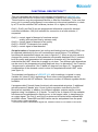
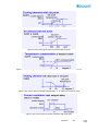
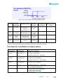
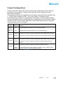
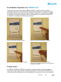
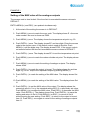
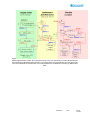
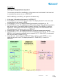
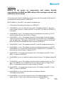
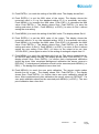
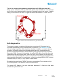
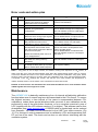
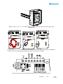
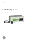
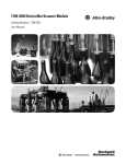
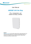
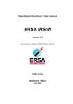
Gas and Air Sensors
User Manual
aSENSE VAV
CO2 / temperature sensor with built-in
general purpose controller
General
The IAQ-sensor product aSENSE VAV is used to measure indoor air carbon dioxide
concentration and temperature. It is a very flexible controller with programmable
outputs for both relay- and linear control of e.g. mixed air dampers, humidifier and
fans. The measured values are shown on the display.
The linear output functions are pre-programmed for different ventilation strategies for
stand-alone control. The units can alternatively be connected to common VAV
(Variable Air Volume) controllers, or Direct Digital Control (DDC). All functions can be
modified from a PC with the RS232 communication cable.
Figure 1 aSENSE VAV
Document
Rev
Page
1 (18)
FUNCTIONAL DESCRIPTION****
This part describes the function of the standard configuration of aSENSE VAV.
Please note that the four outputs may completely or partly have other functions.
These functions may be programmed before or after the installation. To be sure that
every unit is correctly programmed, in accordance to the actual application, a check
by a PC and the standard UIP software (version 4.3 or higher) is necessary.
Out(1), Out(2) and Out(3) are pre-programmed alternative outputs for demand
controlled ventilation. Out(4) is intended for connection to a heat activator, if
requested.
Out(1) = control signal of demand of coolness and air
quality (with reduced flow by extreme cold)
Out(2) = control signal of demand of air quality
Out(3) = ON/OFF of demand of air quality
Out(4) = control signal of heat demand
Set point values of temperature (air cooling and heating) and air quality (CO2) can
be adjusted individually by the unit’s maintenance push buttons. The different
functions with associated outputs are seen in figures 2-7. When a set point value is
changed the control curves of that parameter are parallel displaced! Out(1) controls
both air quality and temperature but temperature overrules so if the temperature
sinks below the LIMIT value the air supply is cut down. Two different gain alternatives
can be used in the temperature/cooling feed-back loop. In alternative 1 the P-band is
1 degree and in alternative 2 the P-band is 2 degrees (see figure 2). Temperature
compensation of the demand control is done for temperatures below LIMIT value
(see figure 4).
The standard configuration of aSENSE VAV, with its settings, is typical in many
Variable Air Volume (VAV) applications. Even other control parameters can be
programmed from the UIP software. There are a number of different regulator blocks
available:
6 programmable P-bands (linear functions) with associated set points, 2 additional
general purpose P-bands, plus 1 timer function regulator controlled by the DI1terminal are available. In addition, the different regulator outputs may be mixed
together using 3 multiplexer (4:1) blocks. To each of the 4 outputs 4 of the available
functions can be addressed so that the sum, or the largest value, is transformed to
an output signal. The Out(1) and Out(2) outputs can be limited within defined MIN
and MAX values. These MIN and MAX values can be set/updated from the push
button menu under operation.
*** Functional description in detailed block diagram form, installation manuals etc, are available on the Internet!
Document
Rev
Page
2 (18)
Figure 2 The control signal of the cooling demand with set point
Figure 3 The control signal of the air demand with set point
Figure 4 The control signal of the temperature compensation with LIMIT = set point –5 oC
Figure 5 The control signal of heating demand with –3 oC dead zone to the set point
Figure 6 The control signal of forced ventilation with delay timer
Document
Rev
Page
3 (18)
Figure 7 The control signal of air demand with set point
Terminal
Standard
Standard settings*
configuration
Standard
function
Out(1)
0-10VDC
600-900 ppm CO2
o
23-24 C
o
Cut off 18-17 C
Air control
alt 1
Out(2)
0-10VDC
600-900 ppm CO2
Air control
alt 2
Relay
Closed
Open
>600 ppm CO2
< 500 ppm CO2
Air control
alt 3
Out(4)
0-10 VDC
20-18 C
o
Configuration of
this sensor
Settings of this
sensor
Heat control
Table I. Default configuration of aSENSE VAV.
Function description in details with all parameter settings is in a separate document.
Formulas for calculation of output values
Configuration
Output Range
Formula for calculation
0-10 VDC
0-2000 ppm CO2
CO2 value = Volt/10*2000
o
2-10 VDC
Temperature value in C = Volt/10*50
0-2000 ppm CO2
CO2 value = (Volt –2)/8*2000
o
4-20 mA
o
0-50 C
Temperature value in C = (Volt –2)/8*50
0-2000 ppm CO2
CO2 value = (mA-4)*2000/16
o
0-50 C
a-b
o
0-50 C
o
Temperature value in C = (mA-4)*50/16
c–d
Value = (reading-a)/(b-a)*(d-c)+c
a = lowest value of the configuration
b = highest value of the configuration
c = lowest value of the range
d = highest value of the range
Table II. Calculation of CO2 value and temperature value for aSENSE VAV
Document
Rev
Page
4 (18)
Output Configurations
A label on the inner side of the sensor lid shows the configuration of the outputs at
the time of product delivery. A label at the inner side of the top part shows the
terminals and jumpers.
The sensors/controllers are supplied from the factory (unless otherwise ordered) with
0...10VDC linear outputs for Out(1), 2 & 4 (see Table II). If different output
configurations are needed for the application, these have to be reconfigured before
the unit is powered up. Each jumper selection is independent from the others. Default
values are 0-10 V and 0-20 mA. Alternative measuring ranges and other start point
can be selected in the PC software.
Jumper
Jumper for
selection
of P-band
cool range
Position Function
o
alt1
Jumper top position provides 1 C as P-band cool range
alt2
Jumper bottom position provides 2 C as P-band cool range.
o
Current
Connection in position “Current” provides 0/4-20mA output range for Out(1).
Voltage
Connection in position “Voltage” provides 0/2-10VDC output range for Out(1)
Current
Connection in position “Current” provides 0/4-20mA output range for Out(2).
Voltage
Connection in position “Voltage” provides 0/2-10VDC output range for
Out(2).
Voltage
Connection in position “Voltage” provides 0-10VDC for Out(4).
Out(1)
Out(2)
Out(4)
Open
Connection in position “Open collector” provides an open collector output.
collector Max 0,5A, 55VDC / 40VAC (half-wave rectifier).
Table II. Configuration jumpers for aSENSE VAV
Document
Rev
Page
5 (18)
Push Button Operation for aSENSE VAV
This sensor has two push buttons, MENU and ESC, located on the front panel
behind the flip-down lid. The YELLOW LED will acknowledge a successful push by a
short flash. Wait until the LED is turned off before next push. The push button MENU
is available for selection of display value or maintenance commands, whereas ESC
is available to escape back from a selected level.
Figure 8 The sensor with push buttons
Figure 9 The push button MENU is pushed
Figure 10 The push button MENU is pushed
Figure 11 The ENTER command is done by
pushing buttons MENU and ESC at the same time
for about 14 seconds
Display modes
In DISPLAY MODE the DEFAULT operation is that the sensor alternates between
temperature and carbon dioxide readings presentation. The push button MENU(+) is
used to select the indicated value on the display to be the error code or the set points
Document
Rev
Page
6 (18)
of temperature and CO2. The display will always return to the Default display mode
after power up. If a permanent change of default values is requested the PC software
is to be used.
Function
Line
Display
Time
limit
Function description
0
Temperature /
CO2
no
DEFAULT - Normal operation
1
Exxx
yes
Error code. If no error has been detected the code E0 is shown. The
error code is reset with Entr(+-).
2
Present
temperature
and CO2.
set points
no
Toggle between display of temperature and CO2 set point with
MENU(+).
Table III. On the display without entering the maintenance menu
Maintenance level
A number of execution options are available from the MAINTENANCE MENU (see
Table IV). This level is accessed only from the display mode in the set points of
temperature and CO2 selection. A two buttons push and an access code restrict
access, intended for competent trained service personnel only. The Entr(+-)
command is done by PUSHING MENU AND ESC AT THE SAME TIME (hold down
for about 15 seconds). The access code has eight binary digits; one press at
MENU(+) equals 1 and one press at ESC(-) equals 0. The code value can be
changed for your personal choise from the software UIP 4.0. The menu diagram in
detail is shown in the appendix.
Always use the ESC button to return to the DEFAULT mode. Several pushes of the
ESC button may be needed to return to the DEFAULT mode. The Entr(+-) push
(MENU & ESC) eventually leads to execution of functions, which causes temporary
or permanently change of any parameter, that affects the system outputs!
Function
Line
Display
Time
limit
Function description
3
ECxx
yes
Access code to the service menu The default value of the code is
255 (=11111111, that is eight presses on MENU(+)). Press down
MENU(+) and let it scroll until it stops. The last two digits of the code
are shown. Then ENTER to accept the selected code.
4a
SPt
yes
For setting the temperature set point.
4b
The present
temperature
set point
yes
For increase / decrease of the temperature set point. The set
point is increased by stepping with MENU(+) button. Decreasing is
done by stepping with the ESC(-) button.
Document
Rev
Page
7 (18)
5a
SPc
yes
For setting the set point of the CO2 concentration
5b
The present
CO2 set point
yes
6a
AOUt
yes
For increase / decrease of the CO2-concentration set point The
set point is increased by stepping with MENU(+) button. Decreasing
is done by stepping with the ESC(-) button.
.
First step of adjusting the analogue outputs MAX and MIN values
6b
An xx
no
Select analogue output by stepping with MENU(+) button
6c1
SetL
no
Leads to adjustment of the MIN value.
6d1
The present
MIN value in
% of FS
no
Increase the MIN value by stepping with the MENU(+) button.
Decrease by stepping with the ESC(-) button. The output is set to
the MIN value and can be checked with a multimeter.
6e1
Sure
no
The adjustment is saved by pressing Entr(+-). Press ESC to return
without saving.
6c2
SetH
no
Leads to adjustment of the MAX value
6d2
The present
MAX value in
% of FS
no
Increase MAX value by stepping with the MENU(+) button. Decrease
by stepping with the ESC(-) button. The output is set to the MAX
value and can be checked with a multimeter.
6e2
Sure
no
The adjustment is saved by pressing Entr(+-). Press ESC to return
without saving.
7
CALb
yes
7a
Sure
yes
Background calibration = CO2-sensor calibration with fresh air.
An easy way to correct the zero point error. The sensor needs fresh
air (380-420 ppm CO2). The calibration must be confirmed by
pressing Entr(+-).
Confirm that a background calibration shall be done.
8
CAL
yes
Zero point calibration of the CO2 sensor. The sensor needs zero
gas. See the zero point calibration instruction. The calibration must
be confirmed by pressing Entr(+-).
8a
Sure
yes
Confirm that a zero point calibration shall be done.
Table IV. Maintenance functions available on aSENSE VAV to set output limits. Time limit refers to an
internal time-out that returns the LCD and maintenance function back to normal. ENTER is a
simultaneous pressing on MENU and ESC.
PLEASE NOTE! If a power failure happens when the sensor has Out(1)...4 locked to
min/max limits, then the sensor will have this output locked when the power returns.
It is necessary to enter this menu item and release the output manually!
Document
Rev
Page
8 (18)
EXAMPLE I:
Setting of the MAX value of the analogue outputs
The access code is time limited. If the time limit is exceeded the sensor returns to
DEFAULT.
ENTR =MENU(+) and ESC(-) are pushed simultaneously.
1. At the start of the setting the sensor is in DEFAULT.
2. Push MENU(+) once to reach the error code. The display shows E + the error
code number. No error is shown as E000.
3. Push MENU(+) once. The display shows the temperature set point e.g. 20.
4. Push ENTR(+-) once. The display shows EC and two digits. Enter the access
code to the service menu. If the default code is used do like this: Push
MENU(+) until the digits stop. The display shows EC55. If the correct code is
not entered before the time limit exceeds the sensor returns to DEFAULT.
5. Push ENTR(+-) once. The display shows SP t to set the temperature set point.
6. Push MENU(+) once to reach the carbon dioxide set point. The display shows
SP C.
7. Push MENU(+) once to reach the setting of analogue outputs. The display
shows AOUt.
8. Push ENTR(+-) to reach the output to be set. The display shows An and two
digits e.g. An 01. Step to the requested output by pushing MENU(+).
9. Push ENTR(+-) to reach the setting of the MIN value. The display shows Set
L.
10. Push MENU(+) to reach the setting of the MAX value. The display shows Set
H.
11. Push ENTR(+-) to set the MAX value of the output. The display shows the
numerical value in % e.g. the standard setting100.0 % or previously set value.
Push MENU(+) to increase the MAX value. Push ESC(-) to decrease the MAX
value. Push ENTR(+-). The display shows Sure. Push ENTR(+-) to save the
setting and return to Set H. Push MENU(+) or ESC(-) to return to Set H
without saving the new setting. Push ESC(-) to return to the output to be set,
item 12. Push ESC(-) once again to return to the setting of analogue outputs
item 11.
Document
Rev
Page
9 (18)
Figure 12 Maintenance functions available on aSENSE VAV to set output limits. Only flow shart for
setting High limits are shown, but Low limits are set in the very same way. Function blocks that are
time limited are indicated by blue boarders. Time limit refers to an internal time-out that returns the
LCD and maintenance function back to normal. ENTER is a simultaneous pressing on MENU and
ESC.
Document
Rev
Page
10 (18)
EXAMPLE II:
Setting of temperature set point
The access code and the recalibration of the sensor are time limited. If the time limit
is exceeded the sensor returns to DEFAULT.
ENTR =MENU(+) and ESC(-) are pushed simultaneously.
1. At the start of the setting the sensor is in DEFAULT.
2. Push MENU(+) once to reach the error code. The display shows E + the error code
number. No error is shown as E000.
3. Push MENU(+) once. The display shows the temperature set point e.g. 20.
4. Push ENTR(+-) once. The display shows EC and two digits. Enter the access code to
the service menu. If the default code is used do like this: Push MENU(+) until the
digits stop. The display shows EC55. If the correct code is not entered before the
time limit exceeds the sensor returns to DEFAULT.
5. Push ENTR(+-) once. The display shows SP t to set the temperature set point.
6. Push ENTR(+-) once. The display shows the temperature set point e.g. 20.0 oC. Push
MENU(+) to increase the set point value in steps of 0.2oC. Push ESC(-) to decrease
the set point value in steps of 0.2oC.
7. Leave the unit, which returns to DEFAULT after a delay or push ENTR(+-) once
when the set point is set. The display shows SP t. Push ESC(-) to return to
DEFAULT.
Figure 13 Push button selection for setting the temperature set point
Document
Rev
Page
11 (18)
EXAMPLE III:
Setting of set points for temperature and carbon dioxide
concentration, the MAX and MIN values of the analogue outputs and
calibration of the sensor
The access code and the recalibration of the sensor are time limited. If the time limit
is exceeded the sensor returns to DEFAULT.
ENTR =MENU(+) and ESC(-) are pushed simultaneously.
1. At the start of the setting the sensor is in DEFAULT.
2. Push MENU(+) once to reach the error code. The display shows E + the error
code number. No error is shown as E000. (Push ESC(-) to return to DEFAULT if
requested
3. Push MENU(+) once. The display shows the temperature set point e.g. 20.0 C
and the carbon dioxide set point e.g. 750ppm.
4. Push ENTR(+-) once. The display shows EC and two digits. Enter the access
code to the service menu. If the default code is used do like this: Push MENU(+)
until the digits stop. The display shows EC55. If the correct code is not entered
before the time limit exceeds the sensor returns to DEFAULT.
5. Push ENTR(+-) once. The display shows SP t to set the temperature set point.
6. Push ENTR(+-) once. The display shows the temperature set point e.g. 20.0 oC.
Push MENU(+) to increase the set point value in steps of 0.2oC. Push ESC(-) to
decrease the set point value in steps of 0.2oC.
7. Push ENTR(+-) once when the set point is set. The display shows SP t. Push
ESC(-) to return to DEFAULT.
8. Push MENU(+) once to reach the carbon dioxide set point. The display shows SP
C.
9. Push ENTR(+-) once. The display shows the carbon dioxide set point e.g. 750
ppm. Push MENU(+) to increase the set point value in steps of 50 ppm. Push
ESC(-) to decrease the set point value in steps of 50 ppm.
10. Push ENTR(+-) once when the set point is set. The display shows SP C. Push
ESC(-) to return to DEFAULT.
11. Push MENU(+) once to reach the setting of analogue outputs.
The display shows AOUt.
12. Push ENTR(+-) to reach the output to be set. The display shows An and two
digits e.g. An 01. Step to the requested output by pushing MENU(+).
Document
Rev
Page
12 (18)
13. Push ENTR(+-) to reach the setting of the MIN value. The display shows Set L.
14. Push ENTR(+-) to set the MIN value of the output. The display shows the
numerical value in % e.g. the standard setting 0.0 % or previously set value.
Push MENU(+) to increase the MIN value. Push ESC(-) to decrease the MIN
value. Push ENTR(+-). The display shows Sure. Push ENTR(+-) to save the
setting and return to Set L. Push MENU(+) or ESC(-) to return to Set L without
saving the new setting.
15. Push MENU(+) to reach the setting of the MAX value. The display shows Set H.
16. Push ENTR(+-) to set the MAX value of the output. The display shows the
numerical value in % e.g. the standard setting 100.0 % or previously set value.
Push MENU(+) to increase the MAX value. Push ESC(-) to decrease the MAX
value. Push ENTR(+-). The display shows Sure. Push ENTR(+-) to save the
setting and return to Set H. Push MENU(+) or ESC(-) to return to Set H without
saving the new setting. Push ESC(-) to return to the output to be set, item
12.Push ESC(-) once again to return to the setting of analogue outputs item 11.
17. Push MENU(+) to reach the calibration with fresh air. The sensor needs fresh air,
air with 400 ppm carbon dioxide. The display shows CALb. Push ENTR(+-). The
display shows Sure. Push ENTR(+-) to confirm that a background calibration
should be done. After completed background calibration the sensor returns to
DEFAULT. If a background calibration should not be executed push MENU(+) or
ESC(-). The background calibration has a time limit.
18. Push MENU(+) to reach the zero point calibration. The sensor needs carbon
dioxide free air or gas. . The display shows CAL. Push ENTR(+-). The display
shows Sure. Push ENTR(+-) to confirm that a zero point calibration should be
done. After completed zero point calibration the sensor returns to DEFAULT. If a
zero point calibration should not be executed push MENU(+) or ESC(-). The zero
point calibration has a time limit.
Document
Rev
Page
13 (18)
FUNCTIONAL TEST aSENSE VAV
Functional test
The unit has two LED’s - yellow and red - on the front panel (found under the front
lid). These LED’s indicate the status of the controller.
Figure 14 The aSENSE VAV with LEDs, push buttons and display
Yellow LED - ”Call for maintenance” is lit, if an error flag is set or the measurement is
out of range. This information is also shown on the display by the wrench icon. Any
push button press, or executed maintenance function, is acknowledged by emission
from this LED.
Red LED - ”Relay active” is lit, when the relay is activated (contact closed).
A simple and visual functional test can easily be performed. Take a breath and blow
the air from a distance of a few centimetres on the sensor. The sensor will detect a
rapid increase in the carbon dioxide concentration. The red LED is lit when the CO 2
concentration goes above the pre-set value. If the sensor is connected to a controller,
the flow of the ventilation system will eventually increase by change of the fan speed
or opening of a damper actuator (depending on the installation/application).
Test gas verification
If the measurement of a sensor is to be verified, a test gas with carefully determined
concentration of CO2 must be used. For zero calibration pure nitrogen or air that has
passed through a chemical absorber should be used. The Zero Calibration bag can
be used to produce carbon dioxide free air. Check the CO2 value of the display or the
voltage of the output with a multimeter when the value has stabilized.
Document
Rev
Page
14 (18)
This is for sensors with measuring ranges between 0-3000 ppm and 0-4%:
When a zero calibration shall be executed a plastic tube with 2.2 mm outer diameter
and 0,8 mm inner diameter shall be inserted in marked holes of the sensor. A plastic
tubing is connected to the tube. The gas flow should be between 0.3 and 1.0 l/min.
Gas inlet
Gas inlet
Figure 15 Part of the PCB with holes for gas inlets marked
Self-diagnostics
The system contains complete self-diagnostic procedures. A full system test is
executed automatically every time the power is turned on. For aSENSE VAV the
internal voltage regulators and outputs are checked. In addition, constantly during
operation, the sensor probes are checked against failure by checking the valid
dynamic measurement ranges. These different system checks return error bytes to
the system RAM. If any error is detected, the yellow LED will be lit until the error has
vanished and the error flag is reset. “Warm up” and “Out of Range” are the only bits
that are reset automatically after return to normal state. All other error bits have to be
reset manually after return to normal state – either by pushing MENU & ESC buttons
simultaneously for =Entr(+-) or by power off and restart.
By pushing the push button ”MENU” the error code number Exxx is shown on the
LCD. Descriptions of the different codes are listed below.
The yellow LED flashes if an error has been detected. If a fatal error has been
detected the yellow LED is lit.
Document
Rev
Page
15 (18)
Error code and action plan
Bit #
0
Error
code
N/A
1
2
2
4
3
8
4
16
5
32
6
64
7
128
Error description
Fatal Error
Yellow LED continuously flashes.
Push buttons are not operating.
Reserved
Algorithm Error.
Indicate wrong EEPROM
configuration.
Output Error
Detected errors during output signals
calculation and generation.
Self-Diagnostic Error.
May indicate the need of zero
calibration or sensor replacement.
Out of Range Error
Accompanies most of other errors.
Can also indicate overload or failures
of sensors and inputs.
Resets automatically after source of
error disappearance.
Memory Error
Non-fatal error during memory
operations.
Warm Up state
Is always set after power up or power
failure. Resets after restart sequence
Suggested action
Try to restart sensor by power OFF/ON.
Contact local distributor
Try to restart sensor by power OFF/ON.
Check detailed settings and configuration
with UIP software version 4.3 and higher.
Contact local distributor
Check connections and loads of outputs.
Check detailed status of outputs with UIP
software version 4.3 and higher.
Check detailed self-diagnostic status with
UIP software version 4.3 and higher.
Contact local distributor
Try sensor in fresh air.
Check connections of temperature and
relative humidity probe.
Check detailed status of measurements
with UIP software version 4.3 and higher.
See Note 1!
Check detailed settings and configuration
with UIP software version 4.3 and higher.
If it doesn’t disappear in half a minute,
check power stability.
Note 1. Any probe is out of range. Occurs, for instance, during over exposure of CO 2 sensor, in
which case the error code will automatically reset when the measurement values return to normal.
Could also indicate the need of zero point calibration. A background calibration using push button
function ”bCAL” will cure this error (a more exact zero calibration using ”CAL” may be performed later,
if required). If the CO2 readings are normal, and still the error code remains, the temperature or
relative humidity sensor can be defect or the connections to these are broken.
Remark: If several errors are detected at the same time the different error code numbers will be
added together into one single error code!
Maintenance
The aSENSE VAV is basically maintenance free. An internal self-adjusting calibration
function takes care of normal long term drift associated to the CO 2 sensor. To secure
the highest accuracy, a time interval of five years is recommended between CO 2
calibrations, unless some special situations have occurred. A zero calibration can be
performed by use of the push button functions, or for a complete overview by use of
a PC together with the UIP software version 4.3 (or higher). This software can be free
downloaded from www.senseair.com. A RS232-cable is needed and can be ordered
from SenseAir. The cable is to be connected to the UART port slide connector (Fig
15). For change of control parameters and re-calibration (CO2 and temperature) this
PC tool has to be used. The check can be done on site without interfering with the
ventilation system.
Document
Rev
Page
16 (18)
Figure 16 The aSENSE VAV for duct mounting . The temperature probe is the black body in the
sampling tube.
Figure 17 The aSENSE VAV printed circuit board with CO2 sensors for measuring ranges 0-3000ppm,
0-10% och 0-25%. PCBs with long temperature sensors are for duct mounting.
~
+
Figure 18 The connection terminal area of the aSENSE VAV printed circuit board.
Document
Rev
Page
17 (18)
WARRANTY AND LIMITATION OF LIABILITY
1. SenseAir warrants that for a period of twenty-four (24) months following receipt by
Buyer the Product supplied by SenseAir to Buyer will be, under normal use and care,
free from defects in workmanship or material and to be in material conformity with
SenseAir's specifications. Units returned to SenseAir for warranty repairs shall be
shipped to SenseAir, at Buyer’s expense, according to SenseAir's instruction. Within
ninety (90) days of the receipt of product, SenseAir shall replace or repair such units
and shall ship them to Buyer’s designated return destination freight pre-paid.
2. Warranty Limitations. This warranty does not extend to any unit that has been
subject to misuse, neglect or accident; that has been damaged by causes external to
the unit; that has been used in violation of SenseAir's instructions; that has been
affixed to any non-standard Accessory attachment; or that has been modified,
disassembled, or reassembled by anyone other than SenseAir.
3. The retailer is not responsible for any consequential loss or damages, which may
occur by reason of purchase and use of this product. The warranty is, in any event,
strictly limited to the replacement/repair of the product
This product is in accordance with the EMC 2004/108/EC, 92/31/EEG including
amendments by the CE-marking Directive 93/68/EEC
The product fulfils the following demands:
EN 61000-4-2 level 2, EN 61000-4-3 level 2,
EN 61000-4-4 level 4, EN 61000-4-6, EN 61000-4-8 level 4, EN 55022 class B
Document
Rev
Page
18 (18)