1
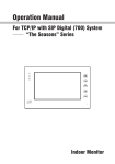
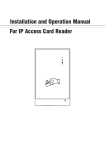
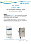
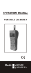
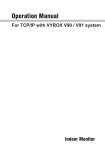
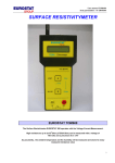
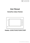
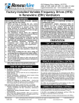
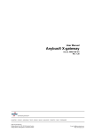
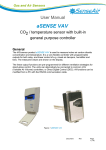
User Manual
tSENSE VAV No Disp
CO2-, temperature- and
relative humidity controller
General
tSENSE VAV No Disp for wall mounting measures indoor air carbon dioxide concentration,
temperature and relative humidity in rooms. The unit connects to Direct Digital Control (DDC).
Linear outputs are pre-programmed as CO2-, temperature- and relative humidity controller. Output
parameters can be modified from PC (Windows) software UIP (version 5 or higher) and USB
communication cable, alternative via Modbus or BACnet.
Table of contents
General ................................................................................................................................................... 1
Opening of housing............................................................................................................................... 3
Download of software UIP5 .................................................................................................................. 3
Output configurations ........................................................................................................................... 3
Out1/Out2/Out3 .................................................................................................................................... 4
Voltage range ................................................................................................................................... 5
Select source .................................................................................................................................... 5
Types ................................................................................................................................................ 5
Proportional-band settings ............................................................................................................... 5
Relay .................................................................................................................................................... 6
Communication settings ...................................................................................................................... 6
Address/Baudrate ................................................................................................................................ 6
Connection configurations ................................................................................................................... 8
Measured values.................................................................................................................................... 9
Temperature unit selection .................................................................................................................. 9
Meter information .................................................................................................................................. 9
Calibration options CO2 ........................................................................................................................ 9
Zero cal/Background/Target cal ........................................................................................................... 9
ABC .................................................................................................................................................... 10
Automatic system test ........................................................................................................................ 10
Error codes and action plans ............................................................................................................. 11
Maintenance ......................................................................................................................................... 11
Directives ............................................................................................................................................. 12
Document
UMA 192
Rev
1
Page
2 (12)
Opening of housing
Figure 1: Opening of housing
Download of software UIP5
senseair.se/products/software/uip-5/
Figure 2: Connection to PC via phone jack
Connect Interface cable USB – 3.5mm Art.no.:00-0-0070
Output configurations
Terminal
Default output
OUT(1)
CO2:
Temperature:
Relative Huminity:
0 - 10 VDC
OUT(2) CO2:
Default output range
Outputs of
this sensor
Output ranges of
this sensor
600 - 900ppm
o
22 - 23 C
75 - 85%
See label
See label
0 - 10 VDC
0 - 2000ppm
See label
See label
OUT(3) Temp:
0 - 10 VDC
0 - 50 C
o
See label
See label
Relay CO2:
0 - 10 VDC
900 - 1000ppm
See label
See label
Table 1. Default output configurations of tSENSE VAV No Disp
Document
UMA 192
Rev
1
Page
3 (12)
Figure 3: Screw Terminal
The sensor is supplied with 0 - 10VDC linear analogue outputs for Out(1), Out(2) and Out(3) (see
Table 1). Alternative output ranges can be configured via PC software UIP (version 5 or later). See
information at senseair.com.
Out1/Out2/Out3
e.g
Each output consists of four blocks. Each block has nine source options.
OUT1 (OUT2/ OUT3/(Relay)) is the largest (Max of a, b , c) demand from Proportional-bands.
UIP5
Out1_a: CO2 has a Proportional-band of 600-900ppm
Out1_b: Temp has a Proportional-band of 22-23°C
Out1_c: RH has a Proportional-band of 75-85%RH
Out1_d: Disabled
Out1_a
CO2 = 714ppm =>3V
Out1_b
Temp = 22.4°C =>4V
Out1_c
Humidity = 80%RH=>5V
Out1_d
Disabled
OUT1=Max of Out1_a/ Out1_b/ Out1_c minus (sub) Out1_d
5V (Out1_c) – 0V (Out1_d Disabled) = 5V => OUT1=5V
The (e.g.) VAV valve opens from minimum set-point position with full opened state at the maximum
set-point.
UOut = 0V
if space has the value:
UOut will be increased
if space has the value:
UOut = 10V
if space has the value:
CO2 ≤ 600ppm
and
Temp ≤ 22°C
and
RH ≤ 75%RH
(Out1_d = Disabled)
600ppm ≤ CO2 < 900ppm
or
22°C ≤ Temp < 23°C
or
75%RH ≤ RH < 85%RH
(Out1_d = Disabled)
CO2 > 900ppm
or
Temp > 23°C
or
RH > 85%
(Out1_d = Disabled)
e.g. Temp protection (Out1_d) Enabled
Out1_a
CO2: 1205ppm=> 10V
Out1_b
Temp: 16.4°C => 0V
Out1_c
Humidity: 80%RH=>5V
Out1_d
Temp: 16.4°C =>10V
NOTE! (sub)
(Temp protection)
OUT1 = 10V (Out1_a) – 10V (Out1_d) = 0V
Document
UMA 192
Rev
1
Page
4 (12)
Voltage range
Max (the same approach with “Min”)
UIP5
Select source
Each output consists of four blocks. Each block has nine source options.
UIP5
❶Source: CO2 selected
❷Save
Types
Analogue/Analogue Invert
(The same approach with “Digital/Digital Invert”)
UIP5
❶Invert ❷Save (Set)
Proportional-band settings
Low (the same approach with ”High”)
UIP5
Document
UMA 192
Rev
1
Page
5 (12)
Outputs
Relay
UIP5
Communication settings
Address/Baudrate
UIP5 Address
❶
❷
❸
❷
❸
UIP5 Baudrate
❶
NOTE!
UIP baudrate ≠ RS-485 baudrate if tSENSE VAV No Disp is connected via phone jack (see fig. 2).
UIP baudrate = RS-485 baudrate if tSENSE VAV No Disp is connected via screw terminal (see fig. 3).
To change settings via UIP requires Reset (Power OFF – Power ON) to execute them.
Document
UMA 192
Rev
1
Page
6 (12)
Connect meter
❶Connect meter
❷
❸Information
Document
UMA 192
Rev
1
Page
7 (12)
Check for updates
❶
❷New version available
❷No new version
❸
❹
Connection configurations
❶
❷ModBus ❸COM14-USB Serial Port ❹Save
❺Lower right corner of screen
❻
NOTE!
UIP baudrate ≠ RS-485 baudrate if tSENSE VAV No Disp is connected via phone jack (see fig. 2).
UIP baudrate = RS-485 baudrate if tSENSE VAV No Disp is connected via screw terminal (see fig. 3).
To change settings via UIP requires Reset (Power OFF – Power ON) to execute them.
Document
UMA 192
Rev
1
Page
8 (12)
Measured values
Temperature unit selection
❶UIP5 Misc
❷
Meter information
Calibration options CO2
Zero cal/Background/Target cal
UIP: If reference meter shows e.g. CO2-value
500ppm set Target to 500
Background calibration button
❶Press 15s, until…
❷Green LED blinks twice
Document
UMA 192
Rev
1
Page
9 (12)
ABC
Enable/Disable
UIP5
ABC period (ABC target / Altitude / Restore cal)
UIP5
Automatic system test
A full system test is executed automatically at every power-up. Sensor probes are checked constantly
during operation against failure by checking valid dynamic measurement ranges.
System checks returns error bytes to RAM. Error codes are available by connecting the sensors to a
PC with a special USB cable (art.no. 00-0-0070) connected (see fig. 2). Error codes are shown in
software UIP (version 5 or higher) at “Meter information - Error Flags””
Document
UMA 192
Rev
1
Page
10 (12)
Error codes and action plans
Bit #
0
Error code
CO2 sensor
Com. error
Error description
No ability to communicate
with CO2 sensor module.
1
CO2 sensor
CO2 measure error
CO2 measurement error.
2
T sensor
T measure error
RH/T sensor
com error
RH/T sensor
RH measure error
RH/T sensor
T measure error
Temp measurement error.
3
4
5
6
7
8
Output config. error
Suggested action
Try to restart sensor by power
OFF/ON.
Contact local distributor.
Try Background calibration (see fig. 4
and 5).
Contact local distributor.
See Note 1!
No ability to communicate
with RH/T sensor module.
RH measurement error.
Temp measurement error,
sensor will use CO2 sensor
temperature if RH/T
Temperature is unavailable.
S_Temp will be set to
NTC_Temp.
Error in output configuration.
Output is still updated,
i.e. can be 0-10V
Try to restart sensor by power
OFF/ON.
Contact local distributor.
Check connections and loads of
outputs.
Check detailed settings and
configuration with UIP software version
5 or later.
Contact local distributor.
Table 2: Error codes and action plans.
NOTE!
Occurs if probe is out of range, at very high CO2 values. Error code resets automatically when
measured values returns to normal. May also indicate need of zero point calibration. If CO 2 values are
normal and error code remains, the sensor can be defect or the connections to it are broken.
If several errors are detected at the same time, different error code numbers will be added together
into one single error code!
Sensor accuracy is defined at continuous operation (at least three (3) weeks after installation).
Maintenance
tSENSE VAV No Disp is maintenance free. Internal self-adjusting calibration function
takes care of normal long term drift. To secure highest accuracy, a time interval of
five years is recommended between CO2 calibrations, unless some special situations
have occurred.
Software can be downloaded free at www.senseair.com.
USB-cable and zero calibration kit can be ordered from SenseAir.
Check can be done on site without interfering with ventilation system.
Document
UMA 192
Rev
1
Page
11 (12)
Directives
This product is in accordance with the
EMC directive 2014/30/EC, 92/31/EEG, RoHS directive 2011/65/EU
including amendments by the CE-marking directive 93/68/EEC
The product fulfils the following demands:
EN 61326-1:2013, Class B equipment
Contact
®
®
®
SenseAir AB Europe
Box 96
Stationsgatan 12
SE- 82060 Delsbo
Sweden
SenseAir North America
29030 SW Town Center Loop East
Suite 202 #169
Wilsonville, OR 97070
USA
SenseAir Asia
®
SenseAir Chengdu Gas Sensors Ltd.
First floor of 8th of Xingke South Road
Jiniu High-Tech, Industrial Park
610036, Chengdu
China
Phone: +46 (0) 653 - 71 77 70
E-mail: [email protected]
Web: senseair.com
Phone: +1 (520) 349-7686
E-mail: [email protected]
Web: senseair.com
Phone: +86 - 028 875 928 85
E-mail: [email protected]
Web: senseair.asia
Document
UMA 192
Rev
1
Page
12 (12)