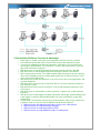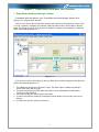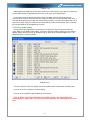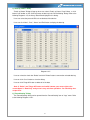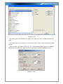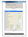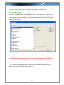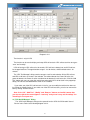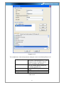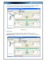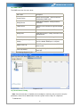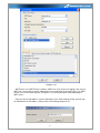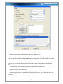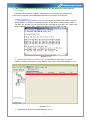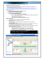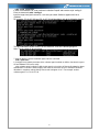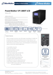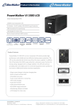
1
PowerWalker-WinPower
User Manual
1
Table of Contents
Chapter 1 PowerWalker-WinPower Introduction ................................................... 4
1. PowerWalker-WinPower profile .......................................................................... 4
2. PowerWalker-WinPower Structure ...................................................................... 4
3. PowerWalker-WinPower Application Range ....................................................... 5
4. PowerWalker-WinPower Functions & Advantages .............................................. 6
Chapter 2 PowerWalker-WinPower Installation, Start & Uninstall ....................... 7
1. System Requirements........................................................................................... 7
2. Platforms supported by PowerWalker-WinPower include the following............... 7
3. PowerWalker-WinPower Installation Steps .......................................................... 7
4. Start/Stop PowerWalker-WinPower ................................................................... 12
5. Uninstall PowerWalker-WinPower .................................................................... 15
Chapter 3 PowerWalker-WinPower User Interface ............................................ 18
1. "PowerWalker-WinPower Manager" window .................................................... 18
2. Menu and Dialog ............................................................................................... 19
1) Auto Search Device .................................................................................... 19
2) “Administrator” Dialog................................................................................. 21
3) "Administrator Password Settings" Dialog ............................................... 21
4) "Event log Viewer" Dialog .......................................................................... 22
5) "Data log Viewer" Dialog ............................................................................ 23
6) “Record Setting” Dialog .............................................................................. 23
7) "Device Control Parameters" Dialog ......................................................... 27
8) "Event Action" Dialog ................................................................................. 34
9) "Shutdown Settings" Dialog ....................................................................... 34
10) "UPS Self-Test Immediately" Dialog ....................................................... 37
11) "UPS Test Manager" Dialog .................................................................... 37
12) "UPS On/Off Manager" Dialog ................................................................ 38
13) "Schedule Viewer" Dialog ........................................................................ 39
14) "Broadcast Message Settings" Dialog .................................................... 40
15) "Email Settings" Dialog ............................................................................ 41
16) "SMS Setting" Dialog................................................................................ 43
17) "Monitor Remote Device" Dialog ............................................................. 44
18) Bottom image ............................................................................................ 45
19) Temp .......................................................................................................... 46
20) Date Format .............................................................................................. 46
21) Advance Settings ...................................................................................... 47
22) Language menu ........................................................................................ 48
23) "Communication Port Settings" Dialog ................................................... 49
24) "SNMP" Menu ........................................................................................... 50
25) "Search Device" Dialog ............................................................................ 50
26) Modify SNMP Device ............................................................................... 51
27) "Add Area" Dialog ..................................................................................... 52
28) "Modify Area" Dialog ................................................................................ 52
29) "SNMP Trap Receiving Port Setting" Dialog .......................................... 53
30) "SNMP Event Log" Dialog ....................................................................... 53
31) "Event Log Setting" Dialog....................................................................... 54
Chapter 4 How to do.............................................................................................. 55
1. How to realize the conversion of the appointed COM port ................................. 55
2. How to realize broadcasting message in LAN .................................................... 56
3. How to realize the schedule of adding/Removing UPS self-test .......................... 59
4. How to realize the schedule of adding/Removing UPS on/off ............................ 63
5. How to realize the network shutdown function ................................................... 67
6. How to realize Setting up shutdown parameter ................................................... 68
2
7. How to realize the modification of Device control parameter ............................. 70
8. How to realize system administrator operation and password modifying realize . 72
9. How to realize sending event message by email ................................................. 73
10. How to realize sending event messages by mobile phone ................................. 75
11. How to realize monitoring device remotely in LAN within the same network .. 77
12. How to realize remote control of any device in different network in LAN ........ 79
13. How to realize the Remote Control of any one of the device in Internet ........... 82
14. How to install software on VMware ESX 3.5/4.0/4.1 ....................................... 86
15. How to install software on Windows 2008 server core ..................................... 90
16. How to install software on VMware ESXi server. ............................................ 91
17. How to configure the computer powered by Multi-UPS shut down safely ...... 100
Appendix A—Glossary Explanation ..................................................................... 104
Appendix B---PowerWalker-WinPower Event Table .......................................... 105
Frequently Asked Questions ................................................................................. 107
3
Chapter 1 PowerWalker-WinPower Introduction
1. PowerWalker-WinPower profile
PowerWalker-WinPower is a device monitoring software, which supports individual computer and
computers connected with network (including LAN & WAN).
It is used to monitor the intelligent device to protect computer systems from being shut down
abnormally when power fails. User can monitor and configure the device on any computer in the
same LAN. With the software, a device can provide security protection for more than one computer
at the same time, including shutting down system in security, saving application data and shutting
down the UPS when power fails.
Note: the diagrams about communication between software and UPS shown in the following
chapters are just for reference. For different model UPS, the display could be different.
2. PowerWalker-WinPower Structure
PowerWalker-WinPower contains three components: Agent, Monitor and TrayIcon.
Note The concrete meaning of Agent refer to Appendix A — glossary explanation.
:
Agent is the key component of PowerWalker-WinPower and runs as a system service on
background. Agent communicates with the device, logs events, notifies users when UPS’s event
happens, arranges actions according to user's requirement and impending shutdown when
necessary. Furthermore, Agent can be managed by Monitor.
Monitor is the user interface application of PowerWalker-WinPower. Relying on Agent, it gathers
real-time information and status of the device, server information and allows user to set the control
parameters of the device. It can run on any computer (individual or connected with network).
TrayIcon is the management tool of PowerWalker-WinPower. It exists on Windows platform only.
It appears in the Status Area of System task bar. TrayIcon has two different icons to display the
current Agent status. The icons and the related status, please refer to the following table 1-2-1.
Indicate the Agent is Stopped.
Indicate the Agent is Running.
Table 1-2-1
When user right clicks the Manager icon, a shortcut menu will be shown. The menu items are
listed as below.
Diagram 1-2-1
The relationship between Agent and Monitor, please refer to the following Diagram 1-2-2.
4
Diagram 1-2-2
3. PowerWalker-WinPower Application Range
Application of individual computers refers to the following Diagram 1-3-1.
Diagram 1-3-1
Application in the LAN refers to the following Diagram 1-3-2.
Diagram 1-3-2
Application in the Internet refers to the following Diagram 1-3-3.
5
Diagram 1-3-3
4. PowerWalker-WinPower Functions & Advantages
When Agent is started, it will protect your equipment continuously in every moment.
Uninstalled easily and clearly with no trace. Never increase the spending of system.
You can have a detailed view about all information of the device, such as utility power,
device type, load and battery. The information is shown in the same window, so you can
take all the information in a glance.
With the function of searching automatically and monitoring any device in the LAN.
With the function of searching manually and monitoring any device in the Internet.
With security protect function. The software administrator password can be set to prevent
others from sabotaging. Only the software administrator has the right of full access, other
users only have the right of view.
With the function of data auto protection, it can close most of the running applications and
save the related files.
With the function of time turning on and off the device, it can give maximum protection to
your computer system.
With the function of time self-test of the UPS, it can provide maximum protection to your
UPS system.
With the function of shutting down system by network, it supplies your system maximum
protection.
With the function of data logging (including utility power, device type, load and battery) and
event logging, so that the software administrator can carry out the device system daily
maintenance.
Flexible means of information transfer let you know the device status at any moment and
anywhere, never miss any one even though the change of time and place.
With the function of broadcasting messages to every users in the network.
With the function of sending messages via pager.
With the function of sending messages by Email.
With the function of sending SMS messages via mobile phone.
6
Chapter 2 PowerWalker-WinPower Installation, Start & Uninstall
1. System Requirements
128 MB physical memory at least (256MB is recommended)
160 MB hard disk space at least
More than 256 colors and 800 * 600 resolutions or above display is recommended
The user is required to have the right as system administrator
On Linux or UNIX operating system, user must log in system with “root” account to carry
out the installation. After installation finished, system need to be reboot
TCP/IP protocol must be installed to support network management
An available communication port (RS-232 Serial Port or USB port) is needed while
connecting to device with a special communication cable.
2. Platforms supported by PowerWalker-WinPower include the following
Windows 98
Windows me
Windows 2000
Windows 2003
Windows 2008
Windows 2008 server core
Windows XP
Windows vista
Windows 7
Windows 8
Windows SBS 2011
Windows server 2012
Linux
Solaris/Sparc 2.6, 7, 8, 9,10
Solaris/Intel 2.6, 7, 8, 9 ,10
HP-UX 11.x, 11i.x (PARISC CPU)
AIX 4.3.3, 5.1, 5.2 , 5.3
Mac OS X
Compaq Tru64 Alpha
SCO UnixWare 7.1.1, 7.1.3
SCO Unix 8.0
FreeBSD x86
SGI Irix 6.5.x
VMware ESX 3.5, 4.0, 4.1
VMware ESXi 4.0, 4.1, 5.0, 5.1
Note: Telecom power only supports the windows platforms.
3. PowerWalker-WinPower Installation Steps
Note: The installation must be started with “root” account in Linux and UNIX systems! And
after installation you must restart the system!
Enter the right directory of the CD according the system platform type.
For GUI mode environment:
Insert the PowerWalker-WinPower CD, find out the operate system of your computer in the CD
directory, Refer to Diagram 2-3-1 as below.
7
Diagram 2-3-1
For Windows platform, enter \Windows directory, run setup.exe to start the installation. Refer to
the following diagram 2-3-2-1.
Diagram 2-3-2-1
Note: For windows vista, windows 7 and windows 2008, enter \Windows directory, you
should run setup.exe as an administrator. Right click on the setup icon, then select “Run as
administrator”, a “user account control” dialog will pop up, please select “Allow”. Refer to
the following diagram 2-3-2-2.
Diagram 2-3-2-2
For Mac OS X platform, enter \MacOSX directory, double click the setup to start the installation.
Refer to the following diagram 2-3-3.
Diagram 2-3-3
For other operating system, execute ./setup.bin or setup_console.bin, Refer to the following
diagram 2-3-4.
8
Diagram 2-3-4
Read the introduction. Refer to the following diagram 2-3-5.
Diagram2-3-5
Click “Next” and input the Serial Number, Refer to the following diagram 2-3-6.
9
Diagram 2-3-6
Click “Next” and choose install folder. Refer to the following diagram 2-3-7.
Diagram 2-3-7
Review the Pre-installation Summary. Refer to the following diagram 2-3-8.
10
Diagram 2-3-8
The installing process, refer to the following diagram 2-3-9.
Diagram 2-3-9
When the installation program is completed, click “Done”. Refer to the following diagram 2-3-10.
11
Diagram 2-3-10
If the software is installed successfully, PowerWalker-WinPower application can be found in the
Start menu\Programs\. Refer to the following diagram 2-3-11.
Diagram 2-3-11
For console mode environment:
1. Enter the directory according the system, run setup.bin or setup_console.bin to start the
installation program.
Note: For UnixWare platform, make sure JRE has been installed in your system,
then enter the /GenericUnix directory to start the setup.
2. Read the information provided, press ENTER to continue the installation.
3. When the installation program is completed, click “Done”.
4. Reboot the Linux and UNIX system after installation.
The installation will set environment variables for PowerWalker-WinPower in /etc/profile file. (For
details to see 'Set environment variable' below). Reboot the system in order to make the setting valid.
4. Start/Stop PowerWalker-WinPower
In Windows operating system
Start Agent:
Run the PowerWalker-WinPower from Start\Program\PowerWalker-WinPower will start the
TrayIcon and Agent. For windows7 operating system, you should restart computer after the first
installation.
Refer to the Diagram 2-4-1 as below.
12
Diagram 2-4-1
The Agent can be start by the following methods:
1) Run the PowerWalker-WinPower from Start\Program\PowerWalker-WinPower will start the
TrayIcon and Agent. Refer to diagram 2-4-1.
2) Right click the agent icon shown on the bottom right corner of the display and select the “Start
Agent” item. Refer to Diagram 2-4-2.
Diagram 2-4-2
3) On all Windows operating system, agent can be started automatically when the computer
reboots.
To start the Monitor, right click the TrayIcon, and select “Start Monitor”, or double click the icon.
Start Monitor:
Right click the TrayIcon and select the "Start Monitor" item. Refer to Diagram 2-4-3.
Diagram 2-4-3
Stop Agent:
Right click the TrayIcon and select the "Stop Agent" menu item. Refer to the following diagram 24-4
Diagram 2-4-4
Exit:
On Windows vista, Windows 2008 and Windows7, if you want to exit, right click the PowerWalkerWinPower Software tray icon, and select “Exit”. Once you exit it, you should restart the computer to
start it automatically. But if you have administrator privilege, you can start it again without restart
computer. There are two steps: the first to start the agent, open the “Services” from the “Start
menu” > “Control Panel” > “Administrative tools”, and find the service “UPSmonitor”, right click on it,
select “Start”. The second to start TrayIcon, click the PowerWalker-WinPower software from Start
menu > Program \ PowerWalker-WinPower.
13
For other windows OS, to exit, right click the PowerWalker-WinPower Software tray icon, and
select “Exit”. If you want to start TrayIcon, just click the PowerWalker-WinPower soft from Start
menu > Program \ PowerWalker-WinPower.
On Mac OS X
Set Agent to be auto started when System boots:
Open “System Preferences -> Accounts -> Login items”; click “+” icon to add the
“Applications/PowerWalker-WinPower/Agent” as Login auto start item. Refer to the following
diagram 2-4-5.
Diagram 2-4-5
Start Agent:
You can double click the agent link in "Applications/PowerWalker-WinPower" directory to start the
Agent.
You can also start it in terminal by enter install directory and execute command:
Enter “/opt/MonitorSoftware” directory and execute command: sudo ./agent start
Start Monitor:
Double click the executable monitor link in "Applications/PowerWalker-WinPower" directory to
start Monitor.
You can also start it in terminal by enter install directory and execute command: sudo ./monitor
Stop Agent:
Enter install directory and execute command:
sudo ./agent stop
On Linux and UNIX:
Start Agent:
Enter “/opt/MonitorSoftware” directory and execute command:
14
./agent start
Start Monitor:
Enter “/opt/MonitorSoftware” directory and execute command:
./monitor
Stop Agent:
Enter “/opt/MonitorSoftware” directory and execute command:
./agent stop
5. Uninstall PowerWalker-WinPower
On Windows operating system
There are two methods of uninstalling PowerWalker-WinPower
One is to click “Uninstall PowerWalker-WinPower” icon in “Start/Program/PowerWalkerWinPower” with left mouse button, refer to Diagram 2-5-1 as below.
Diagram 2-5-1
Note: On Windows Vista, Windows 2008 and Windows 7, make sure you have administrator
privilege, right click and select “Run as administrator”.
The other is to left click “Control Panel/”Add/Remove Program”/Change/Remove(C)” button,
refer to Diagram 2-5-2 as below.
Diagram 2-5-2
Note: Before uninstalling PowerWalker-WinPower, you must stop all PowerWalkerWinPower program first! Otherwise it can't be uninstalled completely.
15
After left click, the Uninstall Program will pop up a dialog shown on Diagram 2-5-3 as below.
Diagram 2-5-3
Click the “Uninstall” to begin to uninstall PowerWalker-WinPower software, refer to the following
diagram 2-5-4.
Diagram 2-5-4
16
Click “Done” and PowerWalker-WinPower has been uninstalled completely. Refer to the following
diagram 2-5-5.
Diagram 2-5-5
On Mac OS X:
Open the Terminal from “Applications/Utilities/Terminal”, execute commands:
cd /opt/MoniorSoftware
sudo ./Uninstall
Input the system account password when it prompts, and uninstall will be carried out with
administrator privilege. The software can be uninstalled completely.
If you only execute the command”./Uninstall”, maybe some files of the software can’t be
uninstalled.
On Linux and UNIX:
Open the Terminal, enter "/opt/MonitorSoftware" directory and execute command:./Uninstall
17
Chapter 3 PowerWalker-WinPower User Interface
1. "PowerWalker-WinPower Manager" window
PowerWalker-WinPower Monitor shows "PowerWalker-WinPower Manager" window, which
displays a list of agents within the LAN.
There is a tree view on the left side of the window, which displays a hierarchical list of items. Such
as “Root”, “networks”, the Agent, the COM port, USB port and the UPS or ATS models or telecom
power. By clicking an item for UPS, the user can expand or collapse the associated list of submenu.
Refer to the following diagram 3-1-1.
Diagram 3-1-1
If you select one of the UPS model from the List, details about it will be displayed on the right side,
Refer to the following diagram 3-1-2.
1. The middle area displays the UPS Status Figure. The Status Figure is different according to
various UPS status and UPS type.
2. The upper area displays the UPS Status Description and recommendation, and the Agent
system times with right align.
3. The lower area displays last two events information.
4. It is able to minimize the window by clicking the minimum button on the top right corner of the
window.
5. It is able to exit from the system by clicking “X”.
18
Diagram 3-1-2
Illustration of UPS Status information bar:
,
The UPS status figure contains five parts: AC LINE, UPS, BATTERY LOAD and BYPASS.
2. Menu and Dialog
1) Auto Search Device
When user select "Auto Search Device" item from "System" Menu, PowerWalker-WinPower will
start searching for the device connect to the computer’s serial port or USB port (for telecom power,
the USB driver must be installed; For ATS, A crossover RS232 cable will be needed that crosses
pins 2 and 3, so that pin 2 on one side is connected to pin 3 on the other.). See the following
diagram 3-2-1-1 and diagram 3-2-1-2. PowerWalker-WinPower can monitor not more than four COM
ports and one USB port in one computer. Only on Windows 98/2000/2003/XP/Vista, Mac OS X and
Linux (with kernel 2.6) can use the USB port. For UPS, no USB driver is needed. But telecom
power's USB communication only works with Windows 2000/XP/Vista and need install the USB
driver at directory USB driver.
19
Diagram 3-2-1-1
Diagram 3-2-1-2
By clicking the item in the tree view, user can get the information following, refer to the diagram 32-1-3.
1) All the computer running PowerWalker-WinPower Agent on the LAN.
2) Device COM Port or USB Port.
3) The model type of Device to which the Agent is connecting.
4) The Current Status of the Agent which user selected in the tree view.
20
Diagram 3-2-1-3
2) “Administrator” Dialog
"Administrator" dialog can be opened by clicking “Act as Administrator” in the “System” menu.
See the following diagram 3-2-2. Enter the administrator password in the edit box and then click
“OK” button. If the password is not correct, the system will pop up a message dialog to prompt users
that the user password is not correct. If the password is correct, users can get the administrator
access right and set up the Agent.
Note: The initial password is “Administrator”.
Diagram 3-2-2
3) "Administrator Password Settings" Dialog
“Administrator Password Settings” dialog can be opened from the “Modify Administrator
Password” menu item of “System” menu. Refer to the following diagram 3-2-3.
21
Diagram 3-2-3
Administrator password only can be set by super user in local machine. If you are not a super user
yet, the "Administrator" Dialog will pop up first for you to log on as an administrator.
User needs to enter a new password in the "New Password" text box and reenter the new
password in the "Confirm Password" text box. If the passwords are not consistent with each other, a
message dialog will pop up to notify the user that the password is not correct and request the user to
enter it once again. If the passwords are consistent with each other and the button "OK" is selected,
the new password will be accepted by the system.
4) "Event log Viewer" Dialog
"Event Log Viewer" Dialog will be shown when user selects the "Event Log" menu item from
"Logs" Menu or click buttons from toolbar, or click the “View log” button of event log in the “Record
Setting” dialog, then the “Event Log” dialog will pop up. Refer to the following Diagram 3-2-4. The
dialog displays a list of history events.
Diagram 3-2-4
User can select the check box “Delete” and click "Delete" button to remove the selected events.
User can click “Close” button to close the dialog.
User can click "Purge All" button to delete all of the events.
Note: If “Delete” and "Purge All" button are invalid, it means your access right to the
current Agent is “Read Only”, you can’t carry out the operation. You should log in as a super
user.
22
5) "Data log Viewer" Dialog
"Data Log Viewer" Dialog will pop up when user selects "Data Log" item of "Logs" Menu , or click
buttons from toolbar or click “View log” button of data log in the “Record Setting” dialog. Refer to the
following Diagram 3-2-5, the history data will be displayed in this dialog.
Users can select the port and UPS to show the data of that device.
Users can click “Next”, “Prev”, “Home” and “End” button to display the data log.
Diagram 3-2-5
User can select the check box “Delete” and click "Delete" button to remove the selected data log.
User can click “Close” button to close the dialog.
User can click "Purge All" button to delete all of the data.
Note: If “Delete” and "Purge All" button are invalid, it means your access right to the
current Agent is “Read Only” and you can’t carry out these operations. You should log in as
a super user.
6) “Record Setting” Dialog
The “Record Setting” dialog can be opened from the “Record Setting” item of “Logs” menu. Refer
to the following Diagram 3-2-6-1.
23
Diagram 3-2-6-1
The default value of the maximum file length of Event Log Viewer is 32KB (the maximum value is
1MB).
Click the “View Log” button of the event log in the “Record Setting” dialog (Refer to the following
diagram 3-2-6-2) to pop up the “Event Log Viewer” dialog (Refer to the following diagram 3-2-6-3)
Diagram 3-2-6-2
24
Diagram 3-2-6-3
Click the “Settings” button of the event log in the “Record Setting” dialog (Refer to the following
diagram 3-2-6-4) to pop up the “Event Action” dialog. Refer to the following diagram 3-2-6-5.
Diagram 3-2-6-4
25
Diagram 3-2-6-5
The default value of the “Maximum file length” in the “Data Log Viewer” is 32KB (the maximum is
1MB).
The default value of record interval in the “Data Log Viewer” is 60 second (the maximum is 3600
second).
Click the “View Log” button of data log in the “Record Setting” dialog (refer to the following
diagram 3-3-5-6) to pop up the “Data Log Viewer” dialog (refer to the following diagram 3-2-6-7).
Diagram 3-2-6-6
26
Diagram 3-2-6-7
Note: Click “Default” button and the parameters in this page will become default. If the
“OK” button is invalid, it means your access right to the current Agent is “Read Only”, and
you cannot setup the parameters. You should log in as a super user.
7) "Device Control Parameters" Dialog
The "Device Control Parameters" Dialog will pop up when user selects "Device Control
Parameters" item of “Device” menu.
For ON-LINE Device, refer to the following diagram 3-2-7-1.
27
Diagram 3-2-7-1
Refer to the following table 3-2-7-1:
28
Parameter
High limit of
input frequency
on bypass
Unit
Hz
-
Maximum
60.0 (for 50Hz
system)
70.0 (for 60Hz
system)
49.0 (for 50Hz
system)
59.0 (for 60Hz
system)
286 (for 1~3K
220V UPS)
132 (for 1~3K
110V UPS)
261 (for 6~20K
UPS)
219 (for 1~3K
220V UPS)
110 (for 1~3K
110V UPS)
209 (for 6~20K
UPS)
-
Minimum
51.0 (for 50Hz
system)
61.0 (for 60Hz
system)
40.0 (for 50Hz
system)
50.0 (for 60Hz
system)
221 (for 1~3K
220V UPS)
110(for 1~3K
110V UPS)
231 (for 6~20K
UPS)
80 (for 1~3K
220V UPS)
40 (for 1~3K
110V UPS)
140 (for 6~20K
UPS)
-
Default
54.0 (for 50Hz
system)
64.0 (for 60Hz
system)
46.0 (for 50Hz
system)
56.0 (for 60Hz
system)
264 (for 1~3K
220V UPS)
132 (for 1~3K
110V UPS)
261 (for 6~20K
UPS)
80 (for 1~3K
220V UPS)
50 (for 1~3K
110V UPS)
176 (for 6~20K
UPS)
Yes
Low limit of
input frequency
on bypass
Hz
High limit of
input voltage on
bypass
V
Low limit of
input voltage on
bypass
V
ON button can
control battery
mode audible
warning
OFF button can
control bypass
mode audible
warning
Do audible
warning when
on bypass
mode
Do audible
warning when
on battery
mode
Restore line
mode when AC
restored
Work on
bypass when
UPS turned off
-
-
-
-
-
-
Yes (for 1~3K
UPS)
No (for 6~20K
UPS)
Yes
-
-
-
Yes
-
-
-
Yes
-
-
-
No (for 1~3K
UPS)
Yes (for 6~20K
UPS)
Table 3-2-7-1
For regular LINE-INT UPS, user can enable/disable battery mode alarm audible though this dialog.
Refer to the following diagram 3-2-7-2:
29
Diagram 3-2-7-2
For special LINE-INT UPS, Refer to the following diagram 3-2-7-3.
Diagram 3-2-7-3
Refer to the following table 3-2-7-3
Parameter
Battery Mode Audible Warning
Value
Yes – Allow audible warning in battery mode
30
Energy Saving
Auto Reboot UPS When AC
Input Restored
Automatic Self-Test
Input Type
Output Voltage Rating
External battery module
number
Running mode enable(only for
vigor)
Frequency slew rate(only for
vigor
Bypass frequency range,
Bypass voltage range, ECO
frequency range, ECO voltage
range(only for vigor)
No – Keep silence in battery mode
Yes – If the load is light, Shut down UPS in 5 minutes
when AC Fail
No – UPS won’t be shut down until battery backup time
exhaust
Yes – Auto-restart enable
No – Auto-restart disable
Yes – Automatic self-test enable
No – Automatic self-test disable
Normal – Accept normal AC line range
Wide range – Accept wide AC line range
Generator – Accept generator’s output
Can be 110V,120V,127V,220V,230V,240V
Only long time discharged model has this option, the
number is from 00 to 10.
Economic mode – enable economic mode
Normal – disable economic mode
Can be 1,2,3
High loss limit and low loss limit
Table 3-2-7-3
For special LINE-INT UPS, Refer to the following diagram 3-2-7-4.
Diagram 3-2-7-4
31
Refer to the following table 3-2-7-4.
Parameter
Battery Mode Audible Warning
Energy Saving
Auto Reboot UPS When AC
Input Restored
Automatic Self-Test
Input Type
Output Voltage Rating
External battery module
number
Value
Yes – Allow audible warning in battery mode
No – Keep silence in battery mode
Yes – If the load is light, Shut down UPS in 5 minutes
when AC Fail
No – UPS won’t be shut down until battery backup time
exhaust
Yes – Auto-restart enable
No – Auto-restart disable
Yes – Automatic self-test enable
No – Automatic self-test disable
Normal – Accept normal AC line range
Wide range – Accept wide AC line range
Generator – Accept generator’s output
Can be 110V,120V,127V,220V,230V,240V
Only long time discharged model has this option, the
number is from 00 to 10.
Table 3-2-7-4
For telecom power, Refer to the following diagram 3-2-7-5
32
Diagram 3-2-7-5
For ATS, Refer to the following diagram 3-2-7-6
Diagram 3-2-7-6
Refer to the following table 3-2-7-6.
Parameter
Buzzer Status
Preferred Source
Synchronization Value
Delay Transfer Time on
Asynchronous
Input Voltage Acceptable
Range
Input Frequency Acceptable
Range
Nominal Voltage
Value
can be Enable, Mute, Disable
1 - The Preferred source is S1
2 - The Preferred source is S2
The value can be 10, 15, or 20. If the phase difference
between S1 and S2 is less than this value degree, ATS
will regard two input sources as synchronous source
The value can be No delay, half cycle and one cycle.
When switching input source due to preferred source fail
if two input sources are not synchronous, the ATS will
add a period of delay time.
The value can be between 12 and 20. for example ,the
range of input voltage window is +/-12% if this value is 12
The value can be between 5 and 15. for example ,the
range of input frequency window is +/-15% if this value is
15
The value can be 220,230 and 240. This is only available
for HV system
Table 3-2-7-6
33
Note: If the “OK” buttons is invalid, it means that your access right to the current Agent is
“read only” and you can’t carry out setup. You should log in as a super user.
8) "Event Action" Dialog
The “Event Action” dialog can be opened, by clicking “Event Action” item of “Device” menu or
button in the toolbar. Refer to the following diagram 3-2-8. In the “Event Action” dialog, users can
select that which action will be carried out when some events occur. For each event, the actions that
users can select are Record, Broadcast, Email, Send SMS and Send Pager. There are three kind
events, The UPS event list is for UPS, Telecom Power System event list for Telecom Power System
and ATS Event List for ATS.
Diagram 3-2-8
Three grades icon of event: Severity (red), Warning (yellow) and Message (blue).
Note: if you want to use the e-mail notification function, you must setup SMTP server first.
For the detailed information, please refer to “How to realize sending event message by email”.
9) "Shutdown Settings" Dialog
The “Shutdown settings” dialog can be opened from the “Shutdown Parameter” item of the
“Device” menu. Refer to the following diagram 3-2-9.
34
Diagram 3-2-9
The function is only for UPS.
In the “Shutdown Settings” dialog, the setting parameters are shown in the following Table 3-2-9.
Parameter
Unit
Battery
backup time
Minute
Maximum
Value
4320
Minimum
Value
1
Default
Remark
10
When the check box with
the function is selected and
the utility power fails, , the
software will send the
shutdown command to UPS
once the setting time is
expired and the output of
UPS will be turned off
When this check box is
selected, System will be
shut down while the
appointed UPS is being turn
off.
,
Shutdown
System
__
__
__
No
35
Suspend
System
__
__
__
No
Multi-UPS
input
__
__
__
NO
System
shutdown
need time
Minute
99
1
2
Remote
Shutdown
by Agent
XX min
shutdown
system
__
__
__
No
Minute
4320
0
0
Run
Command
File before
Shutdown
__
__
__
Nothing
Shutdown
File Max
Execution
Time
Begin
Shutting
down
immediately
while battery
low
Minute
60
1
1
__
__
__
Yes
Shutdown
remote
Agents'
Conditions
Agents be
Shutdown
__
__
__
__
__
__
__
__
Shutdown
Alarm
Interval
Start
Warning
Minute
60
1
1
Minute
60
1
10
36
When this radio box is
selected, System will be
suspended to disk in
shutdown sequence. This
function only can be carry
out in some Windows
platforms and hibernate
support must be enabled
from /Control Panel/Power
Options/Hibernate .
When the check box is
selected, system won't be
shut down until all the
conditions of all selected
UPS are met.
The time to be needed to
shut down the system,
which is from the beginning
of shutting down to the end
of that.
If Yes, System will be shut
down by specified Agent.
Receiving the specified
agent's shutdown signal,
delay XX minutes. System
will be shut down.
Before system shutting
down, Agent can execute a
file, if this parameter isn’t
null, Agent will not begin to
shut down the system until
the "Execution file before
system shutting down"
ends.
Before system shutting
down, the time to be
needed to execute the
shutdown file.
When this check box is
selected and battery low
event occurs, Agent will
shut down the UPS
immediately, otherwise the
shutting down time will be
controlled by battery backup
time.
The condition can be "UPS
be shutdown" or "The time
on battery exceeds setting
time".
When shutdown condition is
satisfied, Agent will send
shutdown signal to the
appointed remote Agents.
The interval that Agent pop
up an alarm message
before shutting down.
If user has setup schedule
shutting down, AGENT will
before
Scheduled
Shutdown
sound alarm prior to the set
time.
Table 3-2-9
Note: If the “OK” button is invalid, it means that your access right to the current Agent is
“Read Only”, you can’t setup the parameters. You should log in as a super user.
10) "UPS Self-Test Immediately" Dialog
The “UPS Self-Test Immediately” dialog can be opened from the “Battery Self-Test Now” item of
“Device” menu. Refer to the following diagram 3-2-10.
Diagram 3-2-10
The function is only for UPS.
In the “UPS Self-Test Immediately” dialog, users can select the type of self-test: Self-Test for 10
seconds, Self-Test until battery low, Self-Test for XX minutes. The time range of self-test for XX
minutes is from 1 to 99 minutes.
Note: If the “OK” button is invalid, it means that your access right to the current Agent is
“Read Only”, you can’t carry out the operation. You should log in as a super user.
11) "UPS Test Manager" Dialog
The “UPS Test Manager” dialog can be opened from the “Battery Self-Test Schedule” item of
“Device” menu. Refer to the following diagram 3-2-11.
37
Diagram 3-2-11
The function is only for UPS.
The function can be used to display and setup UPS self-test task. UPS self-test task has two types:
“once” and “monthly”.
UPS self-test type: UPS self-test for 10 seconds, UPS self-test to battery low, and UPS self-test
for the appointed time. The appointed time range is 1 to 99 minutes, and the default value is 10
minutes.
The “UPS Test Manager” dialog contains two parts: task list and calendar. All the UPS self-test
and UPS on/off tasks are shown in the calendar. The red dot denotes the Power Off action, the
green dot denotes the Power On action and the blue dot denotes the self-test action. Click the “Add
Test” button and users can setup the special time and monthly UPS self-test task in the popped up
dialog. The self-test task added will be shown in the schedule.
If you select one of the UPS self-test tasks in the list, you can modify the task that has been set
by clicking the “Modify” button. If you select one of the UPS self-test tasks, you also can remove the
task by clicking “Remove” button.
Note: If the “OK”, “Add Test”, “Modify” and “Remove” buttons are invalid, it means that
your access right to the current Agent is “read only” and you can’t carry out the setting. You
should log in as a super user.
12) "UPS On/Off Manager" Dialog
The “UPS On/Off Manager” dialog can be opened from the “UPS On/Off Schedule” item of
“Device” menu. Refer to the following diagram 3-2-12.
38
Diagram 3-2-12
The function is only for UPS.
The “UPS On/Off Manager” dialog is used to display and set up UPS On/Off tasks. The UPS
On/Off tasks include two types: “Once” and “Weekly”. The UPS Power Off time range (from
shutdown to turning on next time) that can be set is 1-9999 minutes, i.e. the longest power off time is
6 days 22 hours and 39 minutes. The input range for the year is 2002-2035. The “UPS On/Off
Manager” dialog contains task list and calendar. All the UPS self-test and UPS On/Off tasks are
shown in the calendar. We use red dot to denote the Power Off action, green dot to denote the
Power On action and blue dot to denote self-test action in the calendar. Users can setup weekly and
special time’s UPS Power On/Off tasks in the popped up dialog by clicking “Add UPS shutdown”
button. Note: In terms of time, the new added task can’t conflict with the UPS self-test task and UPS
Power On/Off tasks that have been set. If you select one of the UPS self-test tasks in the list, you
can modify the setup task by clicking the “Modify” button. You also can remove the task by clicking
“Remove” button.
Note: If the “OK”, “Add Test”, “Modify” and “Remove” buttons are invalid, it means that
your access right to the current Agent is “read only” and you can’t carry out the setting. You
should log in as a super user.
13) "Schedule Viewer" Dialog
The “Schedule Viewer” dialog can be opened from the “View Schedule” item of the “UPS” menu.
Refer to the following diagram 3-2-13.
39
Diagram 3-2-13
The function is only for UPS.
The “Schedule Viewer” dialog is used to show the set up UPS Power On/Off and self-test tasks.
“Schedule” dialog contains task list and calendar graphic. Only the tasks of the current month are
displayed in the task list. We use red dot to denote the Power Off action, green dot to denote the
Power On action and blue dot to denote the self-test action in the calendar.
14) "Broadcast Message Settings" Dialog
The “Broadcast Message Settings” dialog can be opened from the “Broadcast Setting” item of
“Tools” menu or click broadcast “Setting” button in “Event Action” Dialog. Refer to the following
diagram 3-2-14.
40
Diagram 3-2-14
The "Broadcast To" list box lists the users. The user item must be selected if the user wants to
receive broadcast message. You can add and delete user item by click "Add" and "Remove" button
(Note: the "All Users" and "Domain User" item can’t be deleted). "All Users" means all computers in
LAN. "Domain User" means computers in the same domain with local Agent.
The "UPS message", “Telecom Power System message” and “ATS message list” list boxes list all
the message, you can select the message by click the check box with the message item.
Note: The function is valid only for windows. To receive broadcast message, "Winpopup"
in Windows95/98 and "Messenger Service" in Windows NT/2000/XP must be started. If the
"OK" button is invalid, it means that your access right to the current Agent is “Read only”,
and you can’t carry out the operation. You should log in as a super user.
15) "Email Settings" Dialog
The “E-Mail Settings” dialog can be opened from the “E-Mail Setting” item of “Tools” menu or click
E-Mail “Setting” button in “Event Action” Dialog. Refer to the following diagram 3-2-15.
41
Diagram 3-2-15
The included items of the email parameter setting are shown in the following Table 3-2-15.
SMTP Server Name
SMTP Account Name
Password
Port
Encryption
This is the mail server, which is used to
send emails to the appointed users. It could
accept two formats: IP address and host
name. For example: smtp.163.com
This is the account for logging in the server.
Enter the complete address format here.
For example: [email protected]
Input the SMTP account password in
needed
This is the port for SMTP
Encryption technique mode
Table 3-2-15
42
The “Receiver E-Mail Address” list box lists the email addresses. Click "Add" button to add an
email address item. Select an address item and click "Remove" button will delete the item. Selected
an email address item, and click the "Test" button will send a test email to the email address.
The "UPS message", “Telecom Power System message” and “ATS message list” list boxes list all
the message, you can select the message by click the check box with the message item.
All of the SMTP parameter’s default value is vacancy, and it can be setup in the local Agent only.
To send email to the appointed user, the SMTP server name or IP address must be set, or the email
will not be sent successfully.
Note: If you want to send email via Internet, you must have a SMTP account in the Internet.
If the “OK” button is invalid, it means that your access right to the current Agent is “read
only”, and you can’t carry out the parameter setting. You should log in as a super user.
16) "SMS Setting" Dialog
The “SMS Setting” dialog can be opened from the “SMS Setting” item of “Tools” menu or click
Send SMS “Setting” button in “Event Action” Dialog. Refer to the following diagram 3-2-16.
Diagram 3-2-16
43
Below is the use remark of SMS setting:
1. Sender
SMS is sent through GSM modem or mobile phone connected with your computer. User should
select COM port that is being used by GSM Modem or mobile phone, and set baud rate of the COM
port. Locus means that where user is.
2. Receiver:
Receiver is the mobile phones numbers who can receive the SMS. It can be one or more. If the
Event that you have selected occurs, PowerWalker-WinPower will send the event message to the
phone numbers in the "Receiver" list.
3. UPS message, Telecom Power System message and ATS message list
User can select the events that need to be informed by SMS.
Note: If the OK button is invalid, it means that your access right to the current Agent is
“Read Only”, and you can’t carry out the operation. You should log in as a super user.
17) "Monitor Remote Device" Dialog
The "Monitor Remote Device" Dialog will show when user selects "Monitor Remote Device" item of
"Monitor" menu. Refer to the following diagram 3-2-17-1.
Diagram 3-2-17-1
Enter the IP address or host name of an Agent to be monitored, and press “OK” button. If the
agent exists, its information will be shown below the "WAN" node in the tree view of the Manager
window.
Note:
1) The number of remote agent monitored is up to 256.
2) If the software can't communicate with the remote agent in 1 minute, the agent will be kept on the
left tree, and the status of this agent will be "Network Communication Lost".
3) You can delete a remote agent by select the agent node manually, then click the mouse right
button to show a pop up menu, select "Delete" menu item to remove it. Refer to the following
diagram 3-2-17-2.
44
Diagram 3-2-17-2
18) Bottom image
If you select the submenu “BottomImage” of the menu “Preference”, you can change the bottom
image of the interface. Refer to the following diagram 3-2-18.
Diagram 3-2-18
45
19) Temp
The centigrade or Fahrenheit temperature shown in the interface can be changed by selecting the
submenu “Temp” of the menu “Preference”. Refer to the following diagram 3-2-19.
Diagram 3-2-19
20) Date Format
The date format can be changed by selecting the submenu “DateFormat” of the menu
“Preference”. The format is “Year/Month/Day”, “Month/Day/Year” or “Day/Month/Year”. Refer to the
following diagram 3-2-20.
46
Diagram 3-2-20
21) Advance Settings
The font, size, color and bottom image of the interface can be changed by selecting the submenu
“Advance Settings” of the menu “Preference”.
The “Advance Settings” dialog contains two parts: “General” and “BottomImage”.
Refer to the following diagram 3-2-21-1.
Diagram 3-2-21-1
Note: If you click “Default” button, the parameters in this view will be turned into default value.
If the “OK” button is invalid, it means that your access right to the current Agent is “read
only”, so you can’t carry out the parameter setup. You should log in as a super user.
In the “BottomImage” view:
If you click “None” box, the bottom image of the interface is “background color”.
Users can select the color that they want by clicking “Color” box.
Users can select the color and gradient direction that they want by clicking “Gradient” box.
47
Users can select background color, character size and light and shade degree of background text
by clicking “Text” box. The bottom image is the background that has the appointed text.
Users can select the background color, the grid offset, the grid size and the grid light and shade
degree in the background by clicking “Grid” box, the bottom image of the interface is “Grid”.
Users can select the background picture from the popped up list box by clicking the “Picture” box,
the bottom image of the interface is “Picture”.
Refer to the following diagram 3-2-21-2.
Diagram 3-2-21-2
Note: Click “Default” button, the parameters in this view will turn to default value. If the
“OK” button is invalid, it means that your access right to the current Agent is “read only”,
and you can’t carry out the parameter setup. You should log in as a super user.
22) Language menu
Users can select languages in the “Language” menu to display different languages, there are ten
kinds of languages to be selected: “English”, “German”, “French”, “Italian”, “Spanish”, “Polish”,
“Turkish” or “Portuguese”, or “Thai”. Refer to the following diagram 3-2-22
48
Diagram 3-2-22
23) "Communication Port Settings" Dialog
The "Communication Port Settings" dialog can be opened from the "COM Port Setting" item
of "System" menu.
On Linux and UNIX, PowerWalker-WinPower can't detect the serial port devices automatically. If
the system has a Serial Port that can’t be found in the default setting table, you must add it manually
in the "Communication Port Settings" dialog. Refer to the following diagram 3-2-23.
Diagram 3-2-23
The default serial port device, please refer to the following Table 3-2-23.
Platform
Linux
Solaris
HP-UX
AIX
UnixWare
Tru64
FreeBSD
Serial Port Device
/dev/ttyS0 /dev/ttyS1.
/dev/ttya /dev/ttyb
/dev/tty0p0 /dev/tty1p0 /dev/tty0p1 /dev/tty0p2
/dev/tty0 /dev/tty1
/dev/tty1A /dev/tty2A
/dev/tty00 /dev/tty01
/dev/ttyd0 /dev/ttyd1
Table 3-2-23
Note: If the "OK" button is invalid, it means that your access right to the current Agent is
“read only”, so you can’t carry out the parameter setting. You should log in as a super user.
49
24) "SNMP" Menu
The SNMP menu has nine menu items:
Menu Item
Description
Search Device
Search Device window - search for devices
monitored by SNMP cards.
Modify Device
Modify Device window - modify the device
information.
Delete Device
Select this item to delete the appointed SNMP
device.
Add Area
Add Area window - add the SNMP areas.
Modify Area
Modify Area window - modify information of the
appointed area.
Delete Area
Select this item to delete the appointed area.
SNMP Trap Receiving Port
Setting
SNMP Port Setting window - modify the SNMP
port if the default SNMP port is occupied.
SNMP Event Log
SNMP Event Log window - view the SNMP
event records.
Event Log Setting
Event Log Setting window - set the SNMP
event logs.
Refer to the following diagram 3-2-24.
Diagram 3-2-24
25) "Search Device" Dialog
Note: If the Search button is disabled, the current Agent is read-only, and you cannot set up the
parameters. Select “Act as Administrator” from the “System” menu to log in as a Superuser.
To add devices:
50
1. Click the “Search Device” item from the” SNMP” menu.
2. Select which TCP/IP protocol that SNMP support in the Search Device dialog, protocol IPv4 or
IPv6.
For IPv4, both single device and segment device searches are supported. Enter an IPv4 address
in the Start IP field and the End IP field.
For IPv6, user can enter only one IPv6 address other than IP ranges to search. If IPv6 address is
broadcast IP (default IPv6 address is broadcast IP ff02::1), all Network Management Card that
support protocol IPv6 within LAN will be found.
3. Click “Search” button. After searching, the new device displays in the tree view.
4. Double-click the new device node to connect it with the Internet browser of the Network
Management Card. The Link column indicates successful communication. Refer to the following
diagram 3-2-25.
Diagram 3-2-25
26) Modify SNMP Device
Select Modify Device from the “SNMP” menu. You can modify the SNMP device information,
including: Name, Area, Community (the default value is “public”).
Refer to the following diagram 3-2-26
51
Diagram 3-2-26
Note: If the OK button is disabled, the current Agent is read-only, and you cannot set up the
parameters. Select “Act as Administrator” from the “System” menu to log in as a Superuser.
27) "Add Area" Dialog
To open the Add Area window, select “Add Area” from the “SNMP” menu.
You can add areas and relative information. The new areas are displayed below the SNMP node
in the left tree view. Refer to the following diagram 3-2-27.
Diagram 3-2-27
Note: You must select the SNMP node at the left tree view. If the OK button is disabled, the
current Agent is read only, and you cannot perform this task. Select “Act as Administrator” from the
“System” menu to log in as a Super user.
28) "Modify Area" Dialog
Note: If the OK button is disabled, the current Agent is read-only, and you cannot set up the
parameters. Select “Act as Administrator” from the “System” menu to log in as a Super user.
Select “Modify Area” from the “SNMP” menu.
You can modify the appointed area information. Refer to the following diagram 3-2-28.
Diagram 3-2-28
52
29) "SNMP Trap Receiving Port Setting" Dialog
To open the SNMP Port Setting window, select “SNMP Trap Receiving Port Setting” from the
“SNMP” menu.
You can change the SNMP Port if the default Port 162 is occupied by other programs. The range
of the new SNMP Port is 1 to 65535. Refer to the following diagram 3-2-29.
Diagram 3-2-29
Note: You must select the SNMP node at the left tree view. If the OK button is disabled, the
current Agent is read only, and you cannot perform this task. Select “Act as Administrator” from the
“System” menu to log in as a Super user.
30) "SNMP Event Log" Dialog
The Event Log Viewer displays the UPS SNMP event history.
You can view the Event Log by select “Event Log” from the “SNMP” menu.
You can set the length of the event log file by select the “Event Log Setting” from the “SNMP”
Menu.
To delete all data, click Clear All.
Click Close to exit the window. Refer to the following diagram 3-2-30.
53
Diagram 3-2-30
Note: To carry on this operation, you must have administrator privilege. Select “Act as
Administrator” from the “System” menu to log in as a Super user.
31) "Event Log Setting" Dialog
Note: If the OK button is disabled, the current Agent is read-only, and you cannot set up the
parameters. Select “Act as Administrator” from the “System” menu to log in as a Super user.
1. To view the event records for any UPS monitored by a Network Management Card, select the
UPS under the SNMP node in the tree view and select “SNMP Event Log” from the SNMP menu.
The Event Log for UPS opens.
2. To set the maximum Event Log file length for any UPS monitored by the SNMP Card, select
“Event Log Setting” from the “SNMP” menu. The default file length is 5,000 rows, and the maximum
value is 100,000 rows. Refer to the following diagram 3-2-31.
Diagram 3-2-31
54
Chapter 4 How to do
1. How to realize the conversion of the appointed COM port
If the computer with PowerWalker-WinPower has multiple serial ports, PowerWalker-WinPower
can allow the users to change the current serial ports connected to the device via “Auto search
Device” menu. Refer to the following Diagram 4-1-1.
Diagram 4-1-1
There is a tree view on the left displaying a hierarchical list, such as Root, LAN, the Agent name,
the COM port and the Device model. Refer to the following diagram 4-1-2.
Diagram 4-1-2
55
When user selects a device model, "Manager" Window will show detail about the device on the
right.
For Linux and UNIX, PowerWalker-WinPower can't detect the serial port device automatically. If
the serial port can’t be found in the default setting table, you must add it manually in the
"Communication Port Settings" dialog. Refer to the following Diagram 4-1-3.
Diagram 4-1-3
The default serial port devices setting: refer to the following Table4-1-1.
Platform
Linux
Solaris
HP-UX
AIX
UnixWare
Tru64
FreeBSD
Serial Port Device
/dev/ttyS0 /dev/ttyS1.
/dev/ttya /dev/ttyb
/dev/tty0p0 /dev/tty1p0 /dev/tty0p1 /dev/tty0p2
/dev/tty0 /dev/tty1
/dev/tty1A /dev/tty2A
/dev/tty00 /dev/tty01
/dev/ttyd0 /dev/ttyd1
Table4-1-1
Note: For the first time, starting Agent takes more time than later to communicate with the
device. And the software will keep a record of the device. Next time, PowerWalker-WinPower
will start according to the last record. If device COM port, device model or slave address have
been changed, user should click "Auto Search Device" item of "System" menu to get correct
device information.
2. How to realize broadcasting message in LAN
PowerWalker-WinPower has the function of sending the event message to the customer timely via
Windows message service. Refer to the notice in section 13 of Chapter 3 (“Broadcast Message
Settings” Dialog) and Appendix B (PowerWalker-WinPower Event Table) to learn general operation.
Refer to the following diagram 4-2-1.
56
Diagram 4-2-1
Refer to the range of broadcasting, there are three options: All Users, Domain Users and special
users.
All users indicate that the message will be sent to all computers in the same network with this
computer, no matter whether it is in the same domain.
Domain users indicate that the message will be sent to all computers only in the same NT domain
with this computer.
Special users indicate that the message will be sent only to one or a group of defined users, but
not others any more.
To realize the function, you should set up the “Add Broadcast User” dialog first. Refer to the
following diagram 4-2-2.
57
Diagram 4-2-2
In the dialog above, after inputting the computer name which will receive messages, select “OK”
button to finish the setting. The name of the computer which you have keyed in will be displayed in
the “Broadcast Message Settings” dialog. Select the events that will be sent to the users, and press
the “OK” button, the setting will become effective. Refer to the following diagram 4-2-3.
Diagram 4-2-3
Note: Only on Windows, the function can be carried out. To receive broadcast message,
"Winpopup" in Windows95/98 and "Messenger Service" in Windows NT/2000 must be started.
58
3. How to realize the schedule of adding/Removing UPS self-test
Click the “Battery Self-Test Schedule” menu of “Device” menu to popup the “UPS Test Manager”
dialog. Refer to the following diagram 4-3-1.
Diagram 4-3-1
Note: If the “OK” button of the dialog is invalid, it means that your access to the current
Agent is “read only”, and you can’t setup it. You should log in as a super user.
Add the task of UPS self-test
Click the “Add test” button, and will pop up the “UPS Self-test” dialog. Refer to the following
diagram 4-3-2.
59
Diagram 4-3-2
In the dialog, users can make a choice of setting UPS self-test task as in a special time or monthly
from the options of “once” or “monthly”. You may set the start time of UPS self-test in date and time
combo box.
Note: the new self-test task can’t conflict with the UPS self-test or UPS Power on/off task that has
already been set.
You can select one of the self-test modes from the following.
Self-test for 10 seconds
Self-test until the battery low
Self-test for 1 to 99 minutes
Press the “Cancel” button, the dialog will be closed and the setting above is invalid. Press the “Ok”
button, the dialog will be closed and the task setting will present to the task list. Refer to the following
diagram 4-3-3.
60
Diagram 4-3-3
Press the “OK” button to finish the setting. Refer to the diagram 4-3-3.
Modifying UPS self-test task
Select one of the UPS self-test tasks in the task list, click “Modify” button to modify the task that
has been set in the popup dialog. Refer to the following diagram 4-3-4.
61
Diagram 4-3-4
After finishing the modification, click “OK” button to save.
Remove UPS self-test task
Select one of the UPS self-test tasks in the task list. Click “Remove” button to cancel the task.
Refer to the following diagram 4-3-5.
62
Diagram 4-3-5
4. How to realize the schedule of adding/Removing UPS on/off
Click the “UPS On/Off Manager” menu of the “Control” menu, and will pop up the “UPS On/Off
Manager” dialog. Refer to the following diagram 4-4-1.
Diagram 4-4-1
63
Note: the function only for UPS. If the “OK” button of the dialog is invalid, it means that
your access to the current Agent is “read only”, and you can’t modify it. You should log in as
a super user.
Add the task of UPS On/Off
Click “Add UPS On/Off” button, and will pop up “Off UPS” dialog. Refer to the following diagram 44-2.
Diagram 4-4-2
In the dialog, users can make a choice in the setting of UPS Power On/Off weekly or in a special
time via the option of “Once” or “Weekly” in the combo box. Set the UPS off and restart time in the
date and time combo box.
Note: the new task of UPS On/Off can’t conflict with the UPS self-test and UPS On/Off tasks that
have been set.
Click the “Cancel” button, the dialog will be closed and the above settings are invalid. Click “Ok”
button, the dialog is closed and the task settings will be shown in the task list. Refer to the following
diagram 4-4-3.
64
Diagram 4-4-3
Click the “OK” button to finish the settings. Refer to the following diagram 4-4-3.
Modify the task of UPS On/Off
Select one of the UPS On/Off tasks in the task list, click “Modify” button to modify the tasks that
have been set in the popped up dialog. Refer to the following diagram 4-4-4.
65
Diagram 4-4-4
After finish the modification, press the “OK” button to save.
Remove the UPS On/Off task
Select one of the UPS On/Off tasks in the task list, click “Remove” button to remove the task.
Refer to the following diagram 4-4-5.
66
Diagram 4-4-5
5. How to realize the network shutdown function
The function is only for UPS.
Click the “Shutdown Parameter” item of the “Device” menu, and will pop up “Shutdown Settings”
dialog. Refer to the following diagram 4-5-1.
67
Diagram 4-5-1
Remote Shutdown by Agent:
Click the “Add” button in the ”Shutdown Options”, enter IP address of agent in the popped up
dialog, and click the “OK” button to finish the setting. When the Agent received the specified agent's
shutdown signal, system will be shut down in delay time.
Shutdown Remote Agents:
Click the “Add” button in the ”Shutdown Remote Agents”, configure the shutdown conditions, enter
IP address of agent in the popped up dialog, and click the “OK” button to finish the setting. When
shutdown condition is touched off, agent will send shutdown signal to the appointed remote Agents.
6. How to realize Setting up shutdown parameter
The function is only for UPS.
Click the “Shutdown Parameter” item of the “Device” menu, and will pop up “Shutdown Settings”
dialog. Refer to the following diagram 4-6-1.
68
Diagram 4-6-1
Click the “Add” button in the “Shutdown Options”, and enter the IP address or host name of agent
in the popped up “Agent’s IP address” dialog. Refer to the following diagram 4-6-2.
Diagram 4-6-2
Click the “Add” button in the “Shutdown Remote Agents”, and configure the Shutdown conditions
in the popped up “Shutdown Remote Agents” dialog. Click the “Add” button in the “Shutdown
Remote Agents” dialog, and enter the Agent’s IP address or host name in the popped up “Shutdown
Remote Agents” dialog. Refer to the following diagram 4-6-3.
69
Diagram 4-6-3
Configure the shutdown parameter in the dialog:
Shutdown options:
Battery backup time: The time that the UPS's battery is able to supply power when utility power
fails.
Begin Shutdown Immediately when Battery Low: When the check box is selected and battery
low event occurs, Agent will shut down the UPS immediately, otherwise the shutting down
time will be controlled according to battery backup time.
Shutdown System: When this check box is selected, system will be shut down while the
appointed UPS is being turned off.
Suspend System: When the radio box is selected, system will suspend in the disk in shutdown
sequence. The function only can be carry out on some Windows, and hibernate support must
be enabled from /Control Panel/Power Options/Hibernate.
Multi-UPS input: When the check box is selected, system won't be shut down until all the
conditions of all selected UPS are met.
System shut down need time: The time to be needed to shut down the system, from the
beginning of shutdown to the end.
Remote Shutdown by Agent: When the check box is selected, system can be shut down by
other Agent.
XX min shutdown system: Receive the specified agent's shutdown signal, delay XX minutes
and shut down system.
Run Command File before Shutdown: Before system shutting down, Agent can execute a file,
if the parameter isn’t null, agent won’t begin to shut down the system until the execution file
has been executed.
Shutdown File Max Execution Time: Before system shutting down, the time to be needed to
execute the shutdown file.
Shutdown Remote Agents:
Shutdown remote Agent’s Conditions: The condition can be “UPS be shutdown” or “The time
UPS on battery exceed setting time”.
Agents be Shutdown: When shutdown condition is touched off, Agent will send shutdown
signal to the appointed remote agents.
Shutdown Alarm Parameters:
Shutdown Alarm Interval: The interval that agent pops up an alarm message before shutting
down.
Start Warning before Scheduled Shutdown: If user has setup shutting down on schedule,
agent will begin to alarm user before the set time.
7. How to realize the modification of Device control parameter
For ON-LINE UPS:
70
Click “UPS control parameters” item of the “Device” menu, and will pop up “UPS control
parameters” dialog. Refer to the following diagram 4-7-1.
Diagram 4-7-1
The following UPS control parameter can be modified in the dialog:
The limit value of the input frequency: when the frequency of the utility power is out
of this range, UPS will count it abnormal and switch to battery supply.
The limit value of the bypass voltage: when UPS supplies in bypass mode, if the
utility voltage is out of this range, UPS will cut off bypass output.
Allow OFF-Key to Enable/Disable Audible Warning When UPS Works on Bypass: to
choose “Yes”, when UPS is supplied by bypass, users can turn off the bypass
audible alarm (beep once every 2 minutes) by pressing “OFF” button on the UPS
panel for one time, and pressing one more time to recover it. To choose “No”, the
“OFF” button on the UPS panel cannot be used to control bypass audible alarm on
or off.
Allow ON-Key to Enable/Disable Audible Warning When UPS Works on Battery
Mode: to choose “Yes”, when UPS is supplied by batteries, users can turn off the
audible alarm (beep once every 4 seconds) supplied by batteries by pressing “ON”
button on the UPS panel for one time, and pressing one more time the audible alarm
can be turned on again. To choose “No”, the “ON” button on the UPS panel can’t be
used to control the audible alarm supplied by batteries on or off.
Bypass Audible Warning: to choose “On”, when UPS is supplied by bypass, it is
allowed to enable bypass audible alarm. To choose “Silent”, when UPS is supplied
by bypass, it is not allowed to enable audible alarm, at this time the “OFF” button on
the UPS panel can’t turn on the bypass audible alarm.
Battery Mode Audible Warning: to choose “On”, when UPS is supplied by batteries,
it is allowed to enable audible alarm of battery supply. To choose “Silent”, when UPS
is supplied by battery, it is not allowed to enable audible alarm of battery supply. At
this time the “ON” button on the UPS panel can’t turn on the audible alarm of battery
supply.
Work On Bypass When UPS Turned Off: to choose “Yes”, when UPS is not turned
on, it is in the mode of bypass supply. To choose “No”, when UPS is not turned on,
no bypass output is offered.
Auto Reboot UPS When AC Input Restored: to choose “Yes”, when UPS is
71
shutdown for the backup time is exhausted or the battery is in low capacitance, once
the utility power is recovered, UPS can restart automatically to the normal operating
mode. To choose “No”, when the utility power is recovered, UPS can’t restart
automatically but in the mode of being not turned on.
Click “OK” button to save what have modified. Click “Cancel” button to make the modification
invalid. Click “Default” button to make all the settings to default value.
For OFF-LINE UPS:
user can enable or disable battery mode alarm audible by this dialog, Refer to the following
diagram 4-7-2.
Diagram 4-7-2
Click “OK” button to save what have been modified. Click “Cancel” button to make the modification
invalid.
Note: If the “OK” button is invalid, it means that your access right to the current Agent is
“read only”, and you can’t carry out setup. You should log in as a super user.
8. How to realize system administrator operation and password modifying realize
System administrator operation
Click “Act as Administrator” item of “System” menu, and will pop up “Administrator” dialog. Refer to
the following diagram 4-8-1.
Diagram 4-8-1
Enter the system administrator password in the dialog, and click the “OK” button to finish the
setting. If the password is correct, you can get the administrator access right to configure the agent.
If the password is incorrect, warning message will popup. Refer to the following diagram 4-8-2.
72
Diagram 4-8-2
Modifying the system administrator password
Click the “Modify Administrator Password” menu of the “System” menu to popup the “Administrator
Password Settings” dialog. The menu is valid within the local Agent only. Refer to the following
diagram 4-8-3.
Diagram 4-8-3
Enter the new password in the “New Password” edit box, reenter it in the “confirm password” edit
box. Click the “OK” button to finish the setting.
Note: If the “OK” button is invalid, it means that the access right to the current Agent is
“read only”, and you can’t operate. You should log in as a super user.
9. How to realize sending event message by email
Precondition
When event occurs, the precondition of realizing sending message by email is connecting the
computer with PowerWalker-WinPower to the Internet.
Steps
Set “Email Service”: click the “Email setting” item of the “Tools” menu, and will pop up the “Email
Settings” dialog. Refer to the following diagram 4-9-1.
73
Diagram 4-9-1
SMTP Server is the SMTP Server’s address; SMTP User is the account for logging in the server; If
SMTP mail server needs password, authentication user should input the password; Port is for SMTP
service, user should set the right port; Encryption is for selecting encryption mode depending on
SMTP server.
Set the receiver Email Address: click the “Add” button of the “Email Settings” dialog, and then pop
up “Add Receiver E-mail Address” dialog. Refer to the following diagram 4-9-2.
74
Diagram 4-9-2
Enter the Email Address in the “Add Receiver Email Address” dialog, and select “OK” button to
save and exit.
Completing event setting: select one of the events (For example, UPS battery low) from the “Send
message”; and then select the user that has been set in the “Receiver Email Address” list, finally
select the “OK” button to save and exit.
10. How to realize sending event messages by mobile phone
Precondition
The precondition of sending messages by mobile phone is that the computers with PowerWalkerWinPower must have at least one communication port used to be connected to GSM Modem or
mobile phone.
Steps
Configure “SMS”: click the “SMS setting” item of the “Tools” menu, and will pop up the “SMS
Setting” dialog. Refer to the following diagram 4-10-1.
75
Diagram 4-10-1
Below is the use remark of SMS Setting, refer to the diagram 4-10-1.
1. Sender: SMS is sent through GSM modem or mobile phone connected with your computer.
User should select COM port used by GSM Modem or mobile phone, and set baud Rate of this COM
port.
2. Receiver: the mobile phones numbers that can receive the SMS. It can be one or more. If the
event occurs, the software will send the short message to all the phone numbers in the "Receiver"
list.
3. Send message: Use can select the event that need to be informed by SMS.
Another method to select event code:
Select one of the events (for example: AC Fail) from the “Event List”, that is on the left side of the
“Event Action”; and then select “Send SMS” on the right side, finally select the “OK” button to save
and exit.
76
11. How to realize monitoring device remotely in LAN within the same network
Precondition
To realize monitoring device remotely in LAN within the same network, the communication
protocol of the computers with PowerWalker-WinPower must include TCP/IP protocol.
Steps for realization
Keep network communication smooth: test with network command “PING” under command
prompt window. For example, a computer named xc in LAN, whose corresponding IP address is
192.168.1.221, and then you can finish the test with command “ping 192.168.1.221”. Refer to the
following Diagram 4-11-1, which indicates that the physical link of LAN is smooth.
Diagram 4-11-1
Remote Control Permission Switch: This is a selectable menu item. User can click the
submenu “Accept Remote Device” of the “Monitor” menu. Refer to the following diagram 4-11-2.
Diagram 4-11-2
Startup Monitor: Refer to the following diagram 4-11-3.
77
Diagram 4-11-3
Select the Device you want to monitor
You can select the Device from the tree view on the left side of the window.
If the Remote Accept Control Permission Switch of the Agent is not on, you can only monitor but
not control. The submenu “Act as Administrator” of the menu “System” is gray and can’t be selected.
So if you don’t log in as an administrator, you can’t control all of the operation, Refer to the following
diagram 4-11-4.
Diagram 4-11-4
78
If the Remote Control Permission Switch of the Agent is on, you can monitor and control this
device. The submenu “Act as Administrator” of the menu “System” is black and can be selected. So
after you log in as an Administrator, you can control all of the operation, Refer to the following
diagram 4-11-5.
Diagram 4-11-5
12. How to realize remote control of any device in different network in LAN
Precondition
The computers with PowerWalker-WinPower must setup TCP/IP protocol in the
communication protocol.
Steps for realization
Keep the communication smooth: test with network command “PING” under command
prompt window. For example, a computer named tj2k with IP address 192.168.2.228,
you can test with command “ping 192.168.2.228”. Refer to the following Diagram 4-121, which indicates that the physical link of LAN is smooth.
79
Diagram 4-12-1
Remote Control Permission Switch: This is a selectable menu item. User can click the
submenu “Accept Remote Device” of the “Monitor” menu.
Refer to the following diagram 4-12-2.
Diagram 4-12-2
Select the device you want to monitor
Click the “Monitor Remote Device” item of the “Monitor” menu, and will pop up the “Monitor
Remote Device” dialog. Refer to the following diagram 4-12-3.
80
Diagram 4-12-3
User can enter a computer name or IP address in the "Monitor Remote Device" Dialog. Click the
“OK” button to finish the setting.
Now you can find the device in the WAN, Refer to the following diagram 4-12-4.
Diagram 4-12-4
If the Remote Control Permission switch of this Agent is not on, then you can only monitor but not
control. Refer to the following diagram 4-12-5.
81
Diagram 4-12-5
If the Remote Control Permission Switch is on, then you can monitor and control this device. So
after you login as a super user, you can control all of the operation, Refer to the following diagram 412-6.
Diagram 4-12-6
13. How to realize the Remote Control of any one of the device in Internet
Precondition
The computers with PowerWalker-WinPower must setup TCP/IP protocol in the
communication protocol.
The computer with PowerWalker-WinPower has been connected to the Internet.
Steps for realization
82
Keep the communication smooth: test with network command “PING” under command
prompt window. For example, a computer named ssc-test in internet, whose
corresponding IP address is 202.103.190.87, and then you can finish the test with
command “ping 202.103.190.87”. Refer to the following Diagram 4-13-1, which
indicates that the physical link of Internet is smooth.
Diagram 4-13-1
Remote Control Permission Switch: This is a selectable menu item. User can open the
submenu “Accept Remote Device” of the “Monitor” menu. Refer to the following diagram 4-13-2.
Diagram 4-13-2
Startup Monitor: Refer to the following diagram 4-13-3.
83
Diagram 4-13-3
Select the device you want to monitor
Click the “Monitor Remote device” item of the “Monitor” menu, and will pop up the “Monitor
Remote Device” dialog. Refer to the following diagram 4-13-4.
Diagram 4-13-4
User can enter a computer name or IP address in the pop-up "Monitor Remote Device" dialog.
Click the “OK” button to finish the setting.
Now you can find the device in the WAN, select the device from the tree view on the left side of
the window. Refer to the following diagram 4-13-5.
84
Diagram 4-13-5
If the Remote Control Permission switch of this Agent is not on, then you can only monitor but not
control. Refer to the following diagram 4-13-6.
Diagram 4-13-6
If the Remote Control Permission Switch is on, you can monitor and control this device. So after
you login in as a super user, you can control all of the operation, Refer to the following diagram 4-137.
85
Diagram 4-13-7
14. How to install software on VMware ESX 3.5/4.0/4.1
This section describes the installation and configuration of the Software on a VMware ESX
Server.
Software allows you to connect VMware ESX 3.5/4.0/4.1 with a UPS through the RS232 or USB
port.
Please notice: When you want to connect VMware ESX 4.0/4.1 with a UPS through USB
port, you should execute the command to activate the usb.o on your System to make the USB
communication normal, and then restart the VMware ESX 4.0/4.1 server. The command:
esxcfg-module -s "libusb_support=1" usb.o
If you don’t want to input the command above, you can start the agent of software after
first installation. And then restart the VMware ESX 4.0/4.1 server, the USB communication will
be normal.
The software will be monitored and configured by a remote Agent on either a Microsoft
Windows or Linux platform.
The software notifies the VMware server of power events or UPS alerts with pop up broadcast
information on the console. It also safely shuts down the VMware ESX server and the guest
operating system.
Before the VMware ESX system shuts down, use the shutdown.sh script to shut down the
guest operating system.
All operations are tested on VMware server with two guest operating systems (Windows 2003
and Windows XP), when the certain conditions exist, such as:
UPS Battery is low
Battery backup time is reached
Tested operations include:
Safely shuts down the VMware server
Safely shuts down the guest operating system
Software notifies the VMware server of power events or the UPS alerts
Installation
This section provides information about installing and configuring Software on a VMware server
and installing VMware Tools on a guest operating system.
Prerequisites
VMware ESX Server with 125 MB free space for the software.
VMware Infrastructure client must be installed on different machine.
Software Installation
To install the software:
1. Download the software from the Web site or from the CD provided with the UPS.
86
2. Enter the command to install software:
For the CD installation, enter the command:
mount /dev/cdrom /mnt
cd /mnt/Linux
./setup_console.bin
For the download installation, enter the command:
tar –zxvf PowerWalker-WinPower_setup_Linux.tar.gz
cd /mnt/Linux
./setup_console.bin
3 Start the Agent. From the installation path, enter the command:
▲
▲
./agent start
Installing VMware Tools on a Microsoft Windows Guest
To install the VMware Tools for a Microsoft Windows guest:
1. On the VM Templates page, move the pointer over the virtual machine template name and
select View Console from the menu.
2. Insert and start the Microsoft Windows operating system installation CD.
3. Log in to the guest operating system inside the virtual machine console, and then click install
VMware Tools.
4. From within the guest operating system, click OK to confirm that you want to install VMware
Tools and launch the Install Shield wizard.
If auto-run is enabled in the guest operating system (the default setting for Microsoft
Windows operating systems), a window opens.
If auto-run is not enabled, run the VMware Tools installer. Click Start > Run and enter
D:\setup.exe, where D: is the first virtual CD-ROM drive.
5. Follow the on-screen instructions.
On Microsoft Windows Server 2003, the SVGA driver is installed automatically, and the
guest operating system uses it after it reboots.
After you install VMware Tools, Microsoft Windows 2000 and Microsoft Windows XP guest
operating systems must be rebooted to use the new driver.
▲
▲
▲
▲
Installing VMware Tools on a Linux Guest
The VMware Tools installation package is on the VMware server installation CD on the path
\VMware\RPMS.
To install the VMware Tools for a Linux guest:
1. On the VM Templates page, move the pointer over the virtual machine template name and
select View Console from the menu.
2. Insert and start the VMware server installation CD.
3. Log in to the guest operating system inside the virtual machine console, and then click Install
VMware Tools.
4. Mount the CD with the command:
mount /dev/cdrom /mnt
5. Install the package with the command:
cd /mnt/VMware/RPMS
rpm –Uvh VMware-esx-tools-***.i386.rpm
NOTE: The package name is likely to be different.
6. Configure the VMware Tools with the command:
Vmware-config-tools.pl
7. Enter number: 1
8. Start the VMware Tools with the command:
Vmware-toolbox &
VMware Tools on the summary row displays OK if the tools are available (refer to Diagram 414-1):
87
OK indicates that
VMware Tools are
available
Diagram 4-14-1
Configuration
This section explains configuration for the Software and for the VMware server.
Software Configuration
The VMware server works in console mode and can’t be used for configuration. Use a remote
Agent with the same Software version to configure the VMware server.
1. Start the manager interface on the remote software Agent in the Microsoft Windows operating
system.
2. If the two Agents are in the same LAN, the VMware server client will be added to the topology
automatically. Otherwise, add the Agent manually (select Monitor Remote Device from the Monitor
menu). The software will auto search the UPS when the Agent starts for the first time after
installation.
If the search fails:
▲ Select the VMware Server Agent from the tree view.
Acting as the Administrator, select Auto Search Device from the System menu. The UPS
connected with VMware server appears in the LAN tree view.
3. Select Shutdown Settings from the Device menu. Set the battery backup time, and select the
Begin Shutdown Immediately if Battery Low check box and the Run Command File before Shutdown
check box (refer to Diagram 4-14-2).
▲
88
Diagram 4-14-2
VMware Server Configuration
All hardware elements must have an operational network configuration that allows them to
communicate freely with each other. Software uses TCP and UDP for communication with UPS.
1.
Confirm that the following UDP ports are opened on the ESX server Firewall:
2198,2199,2200
2.
Confirm that the following TCP ports are opened on the ESX server Firewall: 2099
For Example:
esxcfg-firewall -o 2198,udp,in,UPSMS
esxcfg-firewall -o 2099,tcp,in,UPSMS
3.
4.
If you want to disable the firewall permanently, enter the command: chkconfig iptables off
To disable the firewall temporarily, enter the command: service iptables stop
89
15. How to install software on Windows 2008 server core
Windows Server 2008 Core OS prepared
Before installing software, please ensure the configuration of Windows Server 2008 Core is
correct, including network settings, port settings.
Note: if you want to set the software by another agent, please shut down the firewall first. If you
want to use the remote desktop function of Windows Server 2008 Core, you should enable the
remote desktop function.
The following command may be useful for you to reference.
Command for shutting down the firewall
Command: netsh firewall set opmode disable
Enable the remote desktop function
1. Enter command “regedit”, open the REGEDIT UI.
2. Edit
HKEY_LOCAL_MACHINE\SYSTEM\CurrentControlSet\Control\Terminal
Server\fDenyTSConnections = 0
3. Open the Port for remote desktop function
Enter command: Netsh firewall set portopening tcp 3389
Software installation
Copy the installation file “setup.exe” to Windows Server 2008 Core.
Enter the path where the installation file exists.
Start to install.
You can install UPS monitoring software in Silent installation method or Interface
installation method.
Silent installation method: Enter command: “setup –i silent” or “setup.exe –i silent”, then
the installation can be started, waiting for a moment to finish the installation.
Interface installation method: Enter command: “setup” or “setup.exe”, then the installation
can be started, please follow “next” button of interface to finish the installation.
Check if the installation is successful:
1. Enter the installation path, the default path is c:\Program file (X86)\
MonitorSoftware, Find file “UPSEVENT.CSV”, Enter command: “type
UPSEVENT.CSV”, the log of agent action will be shown. See the below
screenshot, that means the agent is running.
2.
Enter the installation path, start the interface of UPS monitoring software with the
command “manager”. Software interface will be shown as following picture.
90
3.
Check the status of the processes of UPS monitoring software.
Enter command “tasklist” to open the task manager. See below screenshot, if
these processes are all running, that means the UPS monitoring software is
running normally.
Uninstall software
1. Close the interface of the UPS monitoring software and enter the installation path,
the default path is c:\Program file (X86)\ MonitorSoftware, enter command: “wpExit”
to stop software, waiting for a moment.
2. Enter the installation path, the default path is c:\Program file (X86)\
MonitorSoftware, find the file “UninstallerData”.
You can uninstall software in Silent installation method or with Interface uninstall
method.
Silent uninstall method: Enter the file “UninstallerData” and then enter command:
“Uninstall –i silent” or “Uninstall.exe –i silent” to uninstall the software, then uninstall
can be starting, waiting for a moment to finish uninstall.
With interface uninstall method: Enter the file “UninstallerData” and then enter
command: “Uninstall” or “Uninstall.exe” to uninstall the software with interface, please
follow “next” button of interface to finish uninstall.
16. How to install software on VMware ESXi server.
This section describes the installation and configuration of the Software on VMware ESXi server.
Notice: the version of VMware ESXi should be purchased, because of free of charge
version without some function, software can’t be used normally on free of charge version OS.
The software agent can’t be installed on the hypervisor system, because VMware ESXi doesn’t
have an administrative console for hypervisor. However, the software can be installed on VMware
Infrastructure Management Assistant (VIMA) 1.0 or on vSphere Management Assistant (vMA) to
manage the shutdown of VMware ESXi hosts. You can suspend or shutdown guest operating
systems safely and orderly by configuring the ESXi hypervisor. This allows one software agent on
one guest operating system (VIMA/vMA). The software installed on VIMA or vMA should be
configured to be shut down by another software agent communicating with UPS by RS232 or USB.
Another software agent should be installed on operating system with GUI.
91
The software notifies the VMware server of important message with pop-up broadcast
information on the console. It also safely shuts down the VMware ESXi server and the guest
operating system. Before the VMware ESXi system shuts down, use the shutdownESXi.sh script to
shut down the guest operating system.
All operations are tested on VMware ESXi server with two guest operating systems (SBS 2003
and Red Hat).
Tested operations include:
● Safely shut down of the VMware server
● Safely shut down of the guest operating system
Installation and Configuration
This section provides information about installing and configuring the Software on a VMware
ESXi server and installing VMware Tools and vMA on a guest operating system.
Prerequisites
● VMware ESXi server machine
● VIMA 1.0 or vMA installed as guest
● VMware Infrastructure client installed on a different machine for VMware ESXi Server
configuration
● Secure Copy Protocol (SCP) client like WinSCP to upload packages to the VMware ESXi
server
● The Software installed on the vMA
vMA Installation
To install the vMA application:
1. Go to http://www.vmware.com/support/developer/vima/ to download the software from the
VMware Web site.
2. Unzip the vMA virtual application package.
3. Start the VMware Infrastructure client:
●Select File > Deploy OVF Template.
● Click Browse.
● Select the Open Virtualization Format (OVF) and click Next
● Start VMA, the default user name is vi-admin. Set the password for the first login.
VIMA/vMA Shutdown and Startup Configuration
NOTE: You can configure the physical machine to boot the automatic operating system on
startup. This setting is located in your machine’s basic input/output system (BIOS). For further
information, refer to your specific technical hardware documentation.
NOTE: You can configure the automatic startup and shutdown properties of guest operating
systems as suspended.
● Automatic Shutdown of guest (VIMA/vMA) when ESXi host is shutting down
● Automatic Startup of guest (VIMA/vMA) when ESXi host is starting
To configure VIMA/vMA shutdown and startup:
1. Choose the host server from the left pane tree hierarchy by the Virtual Infrastructure Client
interface and then select the Configuration tab.
2. Select Virtual Machine Startup/Shutdown” from the Software list and click Properties. The
Virtual Machine Startup and Shutdown window opens (see diagram 4-16-1).
3. Enter the settings as shown on the Virtual Machine Startup and Shutdown window:
● For each virtual machine, set delay startup for 10 seconds
● For each virtual machine, set delay shutdown for 30 seconds
92
Diagram 4-16-1
NOTE: All hardware elements must have an operational network configuration that allows them
to communicate freely with each other. The Software uses TCP and UDP for communication with
UPS.
4. Confirm that the following UDP ports are enabled on the VIMA/vMA firewall: 2198, 2199,
2200.
Example commands:
sudo iptables -I INPUT -p udp dport 2198 -j ACCEPT
sudo iptables -I INPUT -p udp dport 2199 -j ACCEPT
5. Confirm that the following TCP port is enabled on the VIMA/vMA firewall: 2099
VMware ESXi Server Configuration
Note: if the shutdown action is Guest OS shutdown, VMware tools must be installed on each
virtual machine. If the shutdown action is Power Off, user is allowed to ignore VMware tools
installation.
When the shutdown action is Guest OS shutdown, to allow interactions between physical and
virtual machines, VMware tools must be installed on each virtual machine. Go to
http://www.vmware.com/pdf/osp_install_guide.pdf to download the VMware Tools Installation
Guide Operating System Specific Packages on the VMware Web site for further information.
Installing VMware Tools on a Microsoft Windows Guest Operating System
To install the VMware Tools for a Microsoft Windows guest operating system:
1. On the VM Templates page, select the virtual machine template name and then select the
Console tab. The Console window opens (see diagram 4-16-2).
93
Diagram 4-16-2
2. Insert and start the Microsoft Windows operating system installation CD.
3. Log in to the guest operating system from the virtual machine console.
4. Select the template name and then right-click and select Guest>Install/Upgrade VMware
Tools from the menu. (see Diagram 4-16-3.)
94
Diagram 4-16-3
5. From within the guest operating system, click OK to confirm that you want to install VMware
Tools and launch the Install Shield wizard.
If auto-run is enabled in the guest operating system (the default setting for Microsoft
Windows operating systems), a window opens
If auto-run is not enabled, run the VMware Tools installer. Click Start > Run and enter
D:\setup.exe, where D: is the first virtual CD-ROM drive.
6. Follow the on-screen instructions.
On Microsoft Windows Server 2003, the SVGA driver is installed automatically, and the
guest operating system uses it after it reboots.
After you install VMware Tools, Microsoft Windows 2000 and Microsoft Windows XP guest
operating systems must be rebooted to use the new driver.
●
●
●
●
Installing VMware Tools on a Linux Guest Operating System
To install the VMware Tools for a Linux guest operating system:
1. On the VM Templates page, select the virtual machine template name and then select the
Console tab. The Console window opens (see diagram 4-16-4).
95
Diagram 4-16-4
2. Insert the VMware server installation CD.
Go to \VMware\RPMS to locate the VMware Tools installation package.
3. Log in to the guest operating system from the virtual machine console (see diagram 4-16-5).
96
Diagram 4-16-5
4. Select the template name and then right-click and select Install/Upgrade VMware Tools
from the menu. (see diagram 4-16-3.)
5. Mount the CD with the command: mount /dev/cdrom /mnt
6. Install the package with the command:
cd /mnt/VMware/RPMS
rpm –Uvh VMware esx*.rpm
NOTE: The package name is likely to be different.
7. Configure the VMware Tools with the command:
vmware-config-tools.pl
8. Enter number: 1
9. Start the VMware Tools with the command:
Vmware-toolbox &
VMware Tools on the summary page displays OK if the tools are available (see diagram 4-16-6).
Diagram 4-16-6
The Software Installation and configuration
NOTE: The "vi-admin" is default user name of vMA without the administrator privilege. If you
can’t install or start software normally, please add “sudo” before every command to act as the
administrator privilege.
To install the software:
1. Start the vMA guest operating system.
2. Download the software from the Web site or from the CD provided with the UPS.
3. Upload the software from Windows to vMA using WinSCP tools.
4. Copy the Linux and InstallerData files from the CD to vMA. Enter the following commands
to access the Linux and InstallerData files:
sudo chmod -R 777 Linux
sudo chmod -R 777 InstallerData
5. Enter the Linux path and then enter the following command to install the software:
cd Linux
97
sudo ./setup_console.bin
6. After install software OK, enter software installation file path and execute script “config.pl”:
Enter the command: sudo ./config.pl
Input the target host ip(or hostname), username, password. Software support multi-hosts
shutdown.
For example: 172.18.127.125 and 172.18.127.110 will be added, refer to the following diagram:
The host information will be saved in hostlist document, refer to the following diagram.
Note: The password will be encrypted.
7. Start the Agent. From the installation path, enter the command:
sudo ./agent start
8. Configure the shutdown parameter of the software agent installed on vMA to shut down the guest
OS and VMware ESXi server safely.
● the software agent installed on vMA should select the check box of Remote Shutdown by Agent
and add the IP of another software agent, and select the check box of Run Command File before
Shutdown in shutdown settings dialog. Please refer to diagram 4-16-7. For example: another
software agent IP is 172.18.127.10.
98
Diagram 4-16-7
Notice: The shutdown settings dialog of the software agent installed on vMA should be
open from the shutdown parameter of device menu, by selecting the agent name on the
manager window of another agent installed on operating system with GUI.
● Another software agent should be installed on operating system with GUI, the agent should
communicate with UPS by RS232 or USB and should configure shutdown remote agents in
shutdown settings dialog. Here the remote agent means the software agent installed on vMA. Please
refer to diagram 4-16-8. For example, the IP of the software agent installed on vMA is 172.18.127.20.
When the shutdown conditions is met, software agent installed on vMA will receive shutdown signal,
and run command file before shutdown to shut down all the guest OS and VMware ESXi server
safely.
99
Diagram 4-16-8
Notice: Another software agent installed on operating system with GUI should be the same
version as the software installed on vMA.
17. How to configure the computer powered by Multi-UPS shut down safely
For local computer: If there are more than one UPS supplying power to the local computer with
software as below 4-18-1, you want to safely shut down or suspend the local computer before all
UPS can’t supply power to the local computer. You should select the “Multi-UPS input” option in the
“shutdown settings” dialog of each UPS and set condition, refer to the following picture 4-17-2. The
local computer won’t be shut down or in suspend mode until all the condition of all UPS is met.
100
Diagram 4-17-1
Diagram 4-17-2
For remote computer without communication with UPS: If there are more than one UPS supplying
power to the remote computer with software, you want to safely shut down or suspend the remote
101
computer before all UPS can’t supply power to the remote computer. You should configure the
software installed on the remote computer to be shut down by another computer, refer to the
following picture 4-17-3, and in the “shutdown settings” dialog of another computer with software
communicating with the two UPS to shut down the remote computer, the shutdown condition of each
UPS should be set separately, refer to the following picture 4-17-4 and 4-17-5. The remote computer
won’t be shut down or in suspend mode until all the condition of all UPS is met.
Diagram 4-17-3
102
Diagram 4-17-4
Diagram 4-17-5
103
Appendix A—Glossary Explanation
Agent—Agent is a background application of the Windows/Unix/Linux operating system.
UPS Battery Low—When Utility Power fails and battery supplies power, if the battery voltage is
lower than a certain value (refer to UPS Specification), UPS will send a warning
tone at intervals of 1 second for battery low.
UPS battery backup time exhausted—Indicates when UPS AC fails, battery supply time has
exceeded the “battery backup time” which has been set (“Battery backup time”
can be set in the “Shutdown parameter” dialog of PowerWalker-WinPower).
UPS output overload—UPS load is more than 110% Rated load.
~
Load too high—UPS load is more than 100% 110% rated load.
Supply power in Bypass mode—For the reason of UPS not on or the hardware fault, the input will
not go through the inverter of UPS, but output directly. At this moment, if AC
fails, UPS will not startup backup battery to supply, so the output will also out of
electricity.
UPS self-test—After UPS’ supply mode is switched from utility power mode to battery mode and
work on for a period of time, return to utility power mode again. The purpose of
self-test: First is to check if it can supply normally in battery mode; second is to
make the battery discharge termly (as every month), that is helpful for the battery
maintenance and can prolong the battery’s service life.
Self-test failure—Indicates that the battery can’t supply power normally in battery mode via selftest .
Battery Backup Time—Indicate the time that battery supplies power when utility power fails. After
this time is used up, the Agent begins to shut down the opened application.
Shutdown File Max Execution Time—The max time shutdown file executes.
System Shutdown Need Time—The time for system shutdown, is also the time from system begins
shut down to turn off UPS outlet.
Remote Shutdown by Agent—Local Agent will shutdown in shutdown delay time after the specified
Agent Shutdown.
Start Warning before Scheduled Shutdown—If user has set time shutdown, PowerWalkerWinPower will begin warning at this time earlier than shutdown.
Shutdown Alarm Interval—Indicate after the shutdown warning begins (include time shutdown
warning and AC fail shutdown warning), interval of each warning.
104
Appendix B---PowerWalker-WinPower Event Table
Serial
Number Event Description
1
2
UPS Battery Low
UPS Battery Time
Exhaust
3
UPS Fail
4
UPS Output Overload
Type of
Message
Serious
Serious
Serious
Serious
Warning
6
Communication Lost
7
AC Fail
On Bypass
9
Bypass without output
10
11
12
13
14
15
16
17
18
19
20
21
22
23
24
25
26
27
Output load is more than 110%
The connection of communication
cable is not good, or communication
port fault.
Warning
Warning
8
Remarks
Can be set as no shutdown system
through “Shutdown parameter”
Can set battery backup time through
“Shutdown parameter”
Warning
Self-test Fail
Phase sequence incorrect Warning
in Bypass
Battery switch not
Warning
engaged
Warning
Load unbalance
Warning
Load too high
Warning
Internal warning
Warning
Maintain cover is open
Information
AC Restore
Information
Communication Create
Information
Agent Start
Information
Agent Stop
Information
System be shutdown
Information
System be Shut down by
Other Agent
Information
Special date Close UPS
Information
Weekly Close UPS
Information
Self-test Start
Information
Self-test cancel
Information
Self-test End
UPS will be switched to bypass mode
for the reason of overload, hardware
fault and so on. Online UPS is also in
bypass mode when it is off, at this
time UPS has no protection function.
Three-phase UPS support
Three-phase UPS support
Three-phase UPS support
Three-phase UPS support
.
.
.
.
.
Set the Agent need to be in response
to through “Shutdown parameter”.
.
.
Self-test begins immediately.
.
.
28
29
30
31
32
33
Information
Special date Self-test Start
Special date Self-test
Information
Cancel
Information
Special date Self-test End
Information
Monthly Self-test Start
Information
Monthly Self-test Cancel
Information
Monthly Self-test End
106
.
.
.
.
.
.
Frequently Asked Questions
Question:
UPS can’t communicate with PowerWalker-WinPower under Debian Etch Stable Core
2.6 18-5-486
Method to fix it:
1.
Here are the procedures to solve this question:
Login in Debian as root, the permission of general user is limited to install
PowerWalker-WinPower.
Debian refuse to login as root, some special settings is needed.
Remark
a. In the login interface, there are three icons: “Language“, “Session“ and
“Action“, choose “Action“
b. Choose the last icon of “configure the login manager” in the dialog pop-up
c. Choose the icon of “security” in the dialog pop-up
d. Choose “allow local system administrator login”
2.
Input the user name of root and the password, and then install the PowerWalkerWinPower manually.
Use the command “./agent start“ to start PowerWalker-WinPower service, and then use
the command of “./monitor“ to start the monitor interface
3.
Copy the document of s99UPS from Linux (attached CD) to /etc/rcS.d,
The file s99UPS is used to start PowerWalker-WinPower service automatically.
When the computer reboots, PowerWalker-WinPower service will be started
automatically. Just need to
start the monitor interface by the command “./monitor“
Remark:
a. If the third step is executed, no matter what the user login in as root or a
general user, the communication with UPS will be successful.
b. If the third step have not been executed, you should login as root, and use the
command “./agent start“ to start PowerWalker-WinPower service. If login in as a
general user, the communication with UPS will be failed
Question:
UPS can’t communicate with PowerWalker-WinPower under RedHat Core 2.6 9
Method to fix it:
Add the word of “none /proc/bus/usb usbdevfs defaults 0 0” to the document “/etc/fstab”
PowerWalker-WinPower can find the UPS when choose the icon of “auto search”.
Question:
Mac 10.5 OS with the terminal interface opened can’t be shut down normally by
PowerWalker-WinPower. The information is shown as the following figure.
107
Method to fix it:
Change the setting of the terminal as the following steps:
1. Click “Terminal” shown on the left corner of Mac 10.5 OS, and select
“Preferences…”, There will be a dialog shown as below. Please select
“Nerver” of “Prompt before closing” in the “Shell” interface.
108