1
US008632017B2
(12) United States Patent
(10) Patent N0.:
(45) Date of Patent:
Kucera et al.
(54)
(56)
DAMPER CONTROL SYSTEM
*Jan. 21, 2014
References Cited
U.S. PATENT DOCUMENTS
(71) Applicant: Honeywell International Inc.,
MorristoWn, NJ (US)
(72) Inventors: David Kucera, MorristoWn, NJ (US);
Shanna L. Leeland, Duvall, WA (US);
Peter M. Anderson, St. Paul, MN (US)
(73) Assignee: Honeywell International Inc.,
MorristoWn, NJ (US)
Notice:
US 8,632,017 B2
3,708,737 A
3,818,297 A
1/1973 Johnson
6/1974 Ha et al.
3,847,350 A
11/1974 Thompson
3,849,350
4,204,833
4,256,257
4,267,965
4,299,554
4,324,944
RE30,936
11/1974
5/1980
3/1981
5/1981
11/1981
4/1982
5/1982
A
A
A
A
A
A
E
Subject to any disclaimer, the term of this
patent is extended or adjusted under 35
Matsko
KmetZ et al.
Pinkerton
Everett
Williams
Weihrich et a1.
KmetZ et al.
(Continued)
FOREIGN PATENT DOCUMENTS
U.S.C. 154(b) by 0 days.
This patent is subject to a terminal dis
claimer.
EP
GB
0356609
2211331
3/1990
6/1989
OTHER PUBLICATIONS
(21) Appl.No.: 13/662,089
(22)
Filed:
Honeywell D896 Automatic Vent Damper, Product Data, 12 pages,
1997.
Oct. 26, 2012
(65)
(Continued)
Prior Publication Data
US 2013/0048743 A1
Primary Examiner * Marc Norman
Feb. 28, 2013
(74) Attorney, Agent, or Firm * Seager Tufte & Wickhem
LLC.
(57)
Related U.S. Application Data
(63)
Continuation of application No. 12/553,795, ?led on
Sep. 3, 2009, noW Pat. No. 8,297,524.
(51)
Int. Cl.
F23L 13/02
F23N 3/00
(52)
nisms. The system may use a heat-to-electric poWer converter
such as a thermopile. Heat may come from a pilot light used
for igniting a ?ame for an appliance. The system may store
electric energy in a storage module Which could be a su?i
(2006.01)
(2006.01)
ciently large capacitor. The system may monitor the position
of a damper in a vent or the like and provide start and stop
U.S. Cl.
USPC ............................ .. 236/1 G; 431/20; 700/302
(58)
ABSTRACT
A damper control system having energy e?icient mecha
Field of Classi?cation Search
USPC ................... .. 236/1 G, 15 BD, 26 A; 431/20;
126/285 R; 700/302
movements of the damper using minimal energy. One Way
that the system may control electrical energy to a damper
motor or another electrical mover of the damper is to use pulse
Width modulated signals.
See application ?le for complete search history.
23 Claims, 8 Drawing Sheets
[10
[11
lsaower
ource
[- — — — — — ~ — —
— — — — — — — — — ——-——j
l
1
Power
Energy
1
Management
Storage
1
l
:
|
|
l
Module
Module
K14
Damper
Dam er
Control
1
Mechazism
Module
:
K15
R16 :
Control Electronics
l
‘
l
/—17
Controller
[13
l
|
US 8,632,017 B2
Page 2
(56)
References Cited
RE37,745 E
U.S. PATENT DOCUMENTS
4,333,002
4,390,123
4,460,329
4,508,261
4,511,790
4,538,980
4,588,875
4,692,598
4,696,639
4,734,658
4,742,210
4,752,210
4,770,629
4,778,378
4,834,284
4,835,670
4,880,376
4,984,981
4,986,468
5,007,156
5,039,006
5,276,630
5,442,157
5,612,629
5,622,200
5,652,525
5,660,328
5,797,358
5,896,089
5,968,393
5,975,884
6,048,193
6,053,130
6,059,195
6,208,806
6,257,871
6,261,087
6,271,505
6,293,471
6,350,967
B1
B1
B1
B1
B1
B1
6/1982
6/1983
7/1984
4/1985
4/1985
9/1985
5/1986
9/1987
9/1987
3/1988
5/1988
6/1988
9/1988
10/1988
5/1989
5/1989
11/1989
1/1991
1/1991
4/1991
8/1991
1/1994
8/1995
3/1997
4/1997
7/1997
8/1997
8/1998
4/1999
10/1999
11/1999
4/2000
4/2000
5/2000
3/2001
7/2001
7/2001
8/2001
9/2001
2/2002
Hoyme
KoZak et al.
Yoshida et al.
Bohan, Jr.
Bohan, Jr.
Tsuchiyama et al.
Trent
Bohan, Jr.
Dolnick et al.
Vandermeyden
Adams et al.
Bartels et al.
Pottebaum
Deisinger
Hurtgen
Habegger
Baldwin et al.
Jackson
Mullin et al.
SchulZe
Mullin et al.
Momber
Brandt et al.
Bowles
Demaline
Dugger
Juntunen et al.
Shellenberger
Adams et al.
Langford
Weiss et al.
Bird et al.
Henderson
Stettin et al.
Scott
5/2003 Troost, IV
6,584,197 B1*
6/2003
6,644,957
6,684,821
6,701,874
6,838,847
6,880,493
6,934,862
6,955,301
6,959,876
7,205,737
7,205,892
7,221,862
7,252,502
7,275,533
7,317,265
7,712,677
7,721,972
7,747,358
7,804,047
8,113,823
8,297,524
KoZak
McCabe
Trent
Blank
KoZak
6/2002 Brandt et al.
6,560,409 B2
B2
B2
B1
B2
B2
B2
B2
B2
B1
B2
B1
B2
B2
B2
B1
B2
B2
B2
B2
B2
2005/0161518 A1*
2005/0247304
2006/0214015
2007/0023333
2010/0173252
2011/0048340
2011/0270544
A1
A1
A1
A1
A1
A1
11/2003
2/2004
3/2004
1/2005
4/2005
8/2005
10/2005
11/2005
4/2007
4/2007
5/2007
8/2007
10/2007
1/2008
5/2010
5/2010
6/2010
9/2010
2/2012
10/2012
7/2005
11/2005
9/2006
2/2007
7/2010
3/2011
11/2011
Boudreaux et al. .... .. 379/413.02
Weiss
Lannes et al.
Schultz et al.
Dragoi et al.
Clifford
Sharood et al.
Munsterhuis et al.
Chian et al.
Bilodeau
Luebke et al.
Miller et al.
Munsterhuis
Soeholm et al.
Chian et al.
Munsterhuis et al.
Bracken et al.
Troost et al.
Zak et al.
GuZorek
Kucera et al.
Munsterhuis ............. .. 236/26 A
Weiss
Furukawa et al.
Mouhebaty et al.
Bracken et al.
Anderson et al.
Kucera et al.
OTHER PUBLICATIONS
Honeywell S8610U Universal Intermittent Pilot Module, Installation
Instructions, 20 pages, Aug. 1996.
Johnson Controls Q135 Automatic Flue Damper System, 8 pages,
1998.
LennoX, “Network Control Panel (NCP), User’s Manual,” 18 pages,
Nov. 1999.
Weil-McLain, Technical Services Bulletin No. SB201, 2 pages, Nov.
20, 2002.
* cited by examiner
US. Patent
Jan. 21, 2014
Sheet 1 of8
US 8,632,017 B2
mvm
mHN
mmH
m:
m ."
mm
mm
mo
23~%,.“
US. Patent
Jan. 21, 2014
Sheet 5 of8
US 8,632,017 B2
US. Patent
Jan. 21, 2014
Sheet 6 of8
Reverse
Damper ~77
Drive
A
figure 5
US 8,632,017 B2
US. Patent
Jan. 21, 2014
Sheet 7 of8
US 8,632,017 B2
Start #81
Start Timer 4
{
/84
Drive Damper <
=
PWM Damper >/——87
Reduced Time Limit
figure 6
End L~93
US. Patent
Jan. 21, 2014
Start
Sheet 8 of8
US 8,632,017 B2
101
/ 109
Increase PWM
Duty Cycle
112
\
Reduce PWM
Duty Cycle
figure 7
US 8,632,017 B2
1
2
DAMPER CONTROL SYSTEM
appear in place since no ?ame-poWered components Which
can regulate the motor supply voltage seem to be commer
cially available.
This present application is a Continuation of US. patent
The present system may solve the problem of the damper
application Ser. No. 12/553,795, ?led Sep. 3, 2009, and
entitled “A Damper Control System”. US. patent application
Ser. No. 12/553,795, ?led Sep. 3, 2009, is hereby incorpo
rated by reference.
moving past the desired position and supply voltage regula
tion. The system may have application to fossil fuel burning
appliances such as a Water heater. The system may have the
folloWing features. The system may use ?ame-poWered con
trol electronics that are capable of controlling a damper motor
supply voltage level. The control electronics may use just one
BACKGROUND
thermopile (for cost reduction) in combination With a storage
capacitor having a large capacitance, or other storage device
The present invention pertains to devices for building con
trol systems and particularly damper control devices.
such as a battery or the like, to provide motor supply voltage
When needed. An example of a large capacitor rating may be
about one farad, although the rating may be signi?cant from
SUMMARY
a fraction of a farad to several farads, depending on a load that
The present invention is a damper control system having
30
a moving damper presents electrically to the capacitor or
equivalent storage device. The capacitor needs to be signi?
cant enough to provide poWer suf?cient to drive the damper in
accordance With the present system. HoWever, if the poWer
from the storage device is too loW, then the driving of the
damper may be stopped; for instance, that stopping Would be
equivalent to a PWM signal having a duty cycle equal to Zero.
In the meanWhile, the storage capacitor may be recharged.
The capacitor or other storage device may be recharged via
poWer management implemented in the control electronics.
A resistor parallel to the damper motor may be eliminated
thus signi?cantly reducing the amount of poWer needed to
operate the damper, and enabling the use of just one thermo
pile combined With a large capacitor or other storage device.
35
be positioned near a normal pilot light or ?ame used for
igniting a ?ame for an appliance. The thermopile or other
heat-to-electric poWer converter may instead be positioned
near much smaller than normal pilot ?ame or light. Such
energy e?icient mechanisms. The invention may use a heat
to-electric poWer converter such as a thermopile. The inven
tion may store the electric energy in a signi?cantly large
capacitor or other electrical storage device. The invention
may monitor the position of a damper in a vent or the like and
20
provide start and stop movements of the damper using mini
mal energy. One among several Ways of controlling electrical
energy to a damper motor or other electrical mover is to use 25
variable pulse Width modulated signals.
BRIEF DESCRIPTION OF THE DRAWING
FIG. 1 is a graph of a damper drive at various voltages;
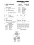
FIG. 2 is a diagram shoWing basic components of a damper
The thermopile or other heat-to-electric poWer converter may
control system;
FIG. 3 and FIG. 4 provide circuit details of the components
of the damper control system shoWn in FIG. 2;
FIG. 4a is a diagram of damper in a vent including a
structure may result in loWer costs compared to a system
camshaft With position sWitches;
using several thermopiles, a normal pilot ?ame or a heating
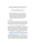
FIG. 5 is a ?oW diagram of an operation of a damper control
?ame. In lieu of a thermopile or other heat-to-electric poWer
system;
FIG. 6 is a ?oW diagram of a more detailed operation of a
damper control system; and
converter, a solar cell and a source of light may be used as a
40 source of poWer. These sources and/or other poWer sources
may be used in a combination.
FIG. 7 is a ?oW diagram of another detailed operation of a
With the present system, moving past the desired position
may be avoided by controlling the motor poWer supply volt
age as the damper approaches the desired position. One Way
damper control system.
DESCRIPTION
45
(PWM), such as reducing the duty cycle to sloW it doWn or
Various guidelines and energy ef?ciency ratings are effec
vice versa. Another Way of control Would be to have a tran
tively forcing Water heater manufacturers to look at neW Ways
sistor connected in series Which could be controlled to limit
the current to the motor driving the damper to sloW it doWn,
to eliminate standby losses. Using a ?ame-poWered control
system in combination With a ?ue damper on a Water heater is
of control may be a use of variable pulse-Width modulation
50
an important step in meeting such guidelines and ratings.
stop it, start it or speed it up. Moving past the desired position
may be further reduced or avoided by connecting an end
sWitch or sWitches in the damper assembly such that the
HoWever, a ?ame-poWered damper motor control may suffer
from the fact that the ?ame-generated supply voltage varies
sWitch or sWitches are not in series With the motor poWer
over a Wider range. Too loW of a voltage may not guarantee
supply. End sWitches may provide information about the
damper position. The end sWitch or sWitches may maintain
proper damper rotation While too large of a voltage may cause
the damper to move past the desired position and continue to
rotate the damper to the Wrong position. To overcome this, a
system may implement at least tWo thermopile devices in
55
contact over a range of angles betWeen a desired open or
closed damper position. This is to ensure that the control
electronics can detect When the desired position is being
approached, and operate to control the motor supply voltage
combination With a resistor parallel to the motor Which con
sumes much poWer.
60
the motor and act to remove current from the motor at a
desired position. This arrangement may further increase the
risk of moving the damper past the desired positioniif the
sWitches turn on again When the damper overshoots the
desired position, the motor may be energiZed again and drive
the damper to the Wrong position. These non-ideal solutions
or current in order to decelerate the rotation such that the
damper reaches and stops at the desired position. An
approaching position may be detected With a timer Which
indicates the time for the damper to reach a certain position.
Also, a system may use end sWitches that are in series With
If the time is deemed too short or too long as indicated by the
65
time the damper reaches the desired position according to the
sWitch or sWitches, then the timer may be re-adjusted (e.g.,
via feedback) to more accurately indicate the time of the
US 8,632,017 B2
3
4
desired position at the next event of damper movement. Such
adjustment may be continuous. The timer may instead be
control the speed and alloW the motor to sloWly coast the
damper into place or destined position. FIG. 1 is a graph of a
damper drive at various voltages. The graph shoWs the motor
regarded as a time period or limit.
drive for three different supply voltages, 1 .4V, 0.9V, and 0.5V
at levels 115, 116 and 117, respectively. Since the higher
voltage drive Will get to the end position faster, the PWM
begins sooner. In the present example, the coasting voltage
The voltage supply may be connected/disconnected, or
adjusted, by a switching device (e.g., transistor) in the control
electronics. Since application safety is taken care of by the
control electronics, a redundant end sWitch in the damper
assembly may be eliminated, further reducing costs. In exist
ing systems, the redundant end sWitch is connected in series
With another end sWitch and the gas main valve and is imple
mented to make the system robust to single failures.
A sensor for indicating a position of the damper may be
may be set to 0.3V for each of the supply voltages; so that the
1.4V supply PWM 118 is at 21%, the 0.9V supply PMW 119
is at 33%, and the 0.5V supply PMW 120 is at 60%. One may
note that FIG. 1 is for illustrative purposes in that the speci?c
voltages and timing parameters used are just examples.
A damper approaching an end position may be detected by
used in lieu of the sWitch or sWitches, e. g., sWitches 44 and 45
in FIGS. 3, 4 and 4a. A potentiometer, Hall sensor, light
a sWitch (in addition to the end sWitch) placed before the end
position or by a shaped sWitch-actuating cam such that the
sWitch remains actuated over a speci?ed range of damper
source and detector, and/or other devices may be used as a
position indicator for a damper.
In addition, the control electronics may be capable of sens
ing Water temperature and controlling gas valves. This may
eliminate the need in some systems in that the temperature
sensor has to provide a pair of contacts. Instead, a combina
rotation. The end position may additionally be determined by
timing the duration of rotation. Based on previous operations,
the time to reach the end position may be estimated and the
20
PWM can start at a pre-determined time.
25
Another Way to stop the motor and damper at the correct
position may include an attempt to stop the motor the instant
the end sWitch is closed. If the sWitch opens again, it may be
assumed that the motor spun past the desired stop point and
that the damper control can reverse motor rotation by chang
tion of a loW cost accurate sensor (e.g., NTC sensor), an
electronically sensed temperature set point, and a safety algo
rithm implemented in the control electronics, may provide
accuracy and safety greater than other systems. Although
some of these items might not relate directly to damper con
ing the drive voltage (for example, by reversing the voltage
trol, they may constitute an important improvement over
other systems.
The present system may have control electronics Which are
?ame-poWered and include a microprocessor capable of man
aging poWer, reading a state of the damper end sWitches, and
controlling electronic sWitches that connect poWer to the
damper motor. The system may be poWered by means of a
single thermopile. When ?ame poWer is available, a large
storage device may be charged. This device may then provide
poWer for the damper at the end of heat cycle to drive it closed,
polarity to a DC motor or reversing the step direction to a
stepper motor). If the damper control is incapable of reversing
or does not reverse the damper motor, then the motor may
30
drive the damper nearly all the Way around again in the same
direction so as to arrive close to the desired stop point. The
motor for moving the damper may be instead an electric
solenoid or other electric mover.
FIG. 2 is a diagram shoWing basic components of a damper
35
control system 10. A source 11 may provide poWer to com
preserve the remaining charge during standby (?ame off), and
ponents of control electronics 12. An output of electronics 12
again provide poWer to the damper at the beginning of the
may be connected to a damper assembly 13 to control a
position of a damper. Control electronics 12 has a poWer
next heat cycle to drive it open. At the very ?rst manual
system start-up, a pilot ?ame may be used to charge the
storage device via the poWer converter, for example in a case
management module 14 having an input connected to the
40
With the damper closed, prior to an opening the damper and
igniting the main ?ame. The main ?ame and/or the pilot light,
having a medium or small siZe, may be used as a source of
heat for a heat-to-electric poWer converter. For other
examples, a solar cell or other kind of light-to-electric poWer
converter may be used along With a source of light such as
ambient light, a bulb, or a ?ame. These different kinds of
poWer sources may be used separately or in combination. The
control electronics or controller may have inputs Which
45
include the energy storage module status, damper position
signals, an appliance request for heat, and other signals useful
for operation of the damper control system.
The present damper assembly may appear similar to other
assemblies; hoWever, the present assembly may have signi?
50
cant differences in that it has no parallel resistor, the end
sWitches are not in series With the motor supply, and the
redundant end sWitch is not present.
55
The damper may be driven With unregulated DC voltage.
The higher the voltage, the faster the motor spins. If the
supply voltage is too loW, the motor Will not be driven (or Will
stop being driven) until the voltage is increased above a
PoWer source 11 may have a thermopile 18 Which converts
thermal energy into electrical energy. The negative terminal
of the thermopile 18 may be connected to a reference voltage
or ground terminal 19 of system 10. The poWer management
module 14 may have a capacitor 22 With one terminal con
nected to terminal 19 and another terminal connected to the
positive terminal 21 of thermopile 18. Capacitor 22 may have
60
a value of about 220 microfarads. Another capacitor 23 may
be connected in parallel With capacitor 22. Capacitor 23 may
speci?ed level. For a given voltage, using adjustable pulse
sloWed by reducing the duty cycle or increased in speed by
When the damper is approaching the open or closed posi
tions, voltage regulation to the motor may begin in order to
energy storage module 15. Electronics 12 may also have a
damper control module 16 With an input connected to the
energy storage module 15 and an output connected to the
damper assembly 13. There may also be a controller 17 con
nected to the poWer management module 14 and the damper
control module 16.
FIG. 3 and FIG. 4 provide circuit details of the components
of damper control system 10 shoWn in FIG. 2. System 10 of
FIG. 3 has a single direction drive for the damper control
module 16. FIG. 4 has a reversible direction drive for module
16. The damper control module 16 may also be referred to as
a motor control or motor control drive.
Width modulation, the motor and driven damper may be
enlarging the duty cycle.
poWer source 11 and an output connected to an input of an
65
have a value of about 100 nanofarads. An inductor 24 may
have one end connected to terminal 21 and the other end
connected to a drain of a ?eld effect transistor (FET) 25.
Inductor 24 may have a value of about 220 microhenries. FET
25 may have a source connected to terminal 19 and a gate
connected to a PWMl output 26 of controller 17. A source of
US 8,632,017 B2
5
6
a PET 27 may be connected to the drain of PET 25. A gate of
PET 27 may be connected to a PWM2 output 28 of controller
17.
A drain of PET 27 may be connected to a terminal 29 Which
is connected to one end of a capacitor 31 of the energy storage
module 15. The other end of capacitor 31 may be connected to
reference terminal 19. Terminal 29 may also be connected to
an AD1 input 32 of controller 17. A Schottky diode 34 may
FIG. 4 may be like damper assembly 13 of FIG. 3. PoWer
source 11 may contain a thermopile 18 in FIG. 4. PoWer
management module 14 of system 10 in FIG. 4 may be like
module 14 of system 10 in FIG. 3.
FIG. 4a is a diagram of damper 42 for a vent 61. The
damper may have camshaft 43 attached for indicating the
position of the damper. In this instance, as driven by motor 41
(not shoWn in FIG. 4a) attached to shaft 43, the damper may
have an anode connected to the source of PET 27 and have a
rotate counterclockWise to open and clockWise to close.
SWitch 45 may close due to a cam lobe on the camshaft When
cathode connected to the drain of PET 27. Diode 34 may have
a model number MBR0530TX. FET’s 25 and 27 may have a
damper 42 approaches closure in a clockWise movement.
model number MGSF2N02ELT1.
Capacitor 31 of energy storage module 15 may be used for
SWitch 46 may close When the damper moves in a counter
clockWise direction into an open position as indicated by a
neW position 6211 of cam lobe 62. SWitch 45 may open upon
a movement of lobe 62 aWay from the sWitch. This is merely
storing energy for system 10. The value of capacitor 31 may
be about one farad. Terminal 29 from capacitor 31 may be
connected to an input of damper control module 16, Which
may be regarded as a motor control. The input of module 16
may be a drain of a PET 35. A gate of PET 35 may be
connected to a PWM3 output 36 of controller 17. A source of
PET 35 may be connected to a cathode of a diode 37. An
one arrangement of position indication of the damper, par
ticularly With one or more sWitches.
20
anode of diode 37 may be connected to reference terminal 19.
A capacitor 38 may be connected in parallel With diode 37.
Diode 37 may have a model number SlG. Capacitor 38 may
have a value of about 100 nanofarads. FET 35 may have the
same model number as FET 27. FET 35, diode 37 and capaci
tor 38 may constitute the damper control module 16 having a
may occur. If the ansWer is yes, then a drive damper may
occur at block 73 and the operation continue onto symbol 74
25
single direction drive motor control for damper assembly 13.
The output of module 16 at terminals 19 and 39 may go to
a motor 41 of damper assembly 13. Motor 41 may drive a
damper 42 having a camshaft 43. End sWitches 44 and 45 may
be situated proximate to the camshaft 43 such that one sWitch
44 operates When the camshaft 43 is in one position and the
other sWitch 45 operates When the camshaft 43 is in another
position. The operation of sWitches 44 and 45 relative to
camshaft 43 is to indicate to the controller 17 a position of the
damper 42 as it is moved by motor 41. SWitch 44 has one
terminal connected to reference terminal 19 and the other
terminal connected to an 1N1 input 46 of controller 17. SWitch
45 may have one terminal connected to reference terminal 19
and the other terminal connected to an 1N2 input 47 of con
troller 17. The end sWitches 44 and 45 may be regarded as a
sWitch mechanism 48. Devices, other than a sWitch or
FIG. 5 is a How diagram of an operation of a damper control
system 10. The operation may begin at start 71 Which leads to
a symbol 72 Where a question of Whether there is a damper
request. If not, then a return to the beginning of symbol 72
30
Where a question of Whether an end sWitch Was made. The end
sWitch may be activated by a cam connected to the damper.
The making of the end sWitch may indicate an opening of the
damper. If the question to symbol 74 is no, the there is a return
to the drive damper block 73. The question of symbol 74 may
be again ansWered. When a yes occurs, then the damper is
stopped at block 75. Then at symbol 76, a question of Whether
an end sWitch Was made is asked. If the answer to the question
is no, it may mean that the end sWitch on the cam connected
35
to damper Was overshot. Then the damper drive may be
reversed at block 77. The approach from block 73 through
symbol 76 may repeated. When an ansWer to the question in
symbol 76 is yes, then the operation may stop at the end block
78.
FIG. 6 is a How diagram of a more detailed operation of a
40
damper control system 10 Which may begin at a start block 81
and proceed to a symbol 82 Where a question concerning a
damper request is asked. If an ansWer is no, then a return to the
sWitches, may be used for damper position detection. Con
entry of symbol 82 may be made. When the ansWer is yes to
troller 17 may be a microcontroller of one kind or another.
the question in symbol 82, then the operation may proceed to
Damper control system 10 in FIG. 4 is similar to system 10
in FIG. 3 except for damper control module 16 for motor
control is different. Terminal 29 may be connected from
45
Was made may be asked. If an ansWer is no, then another
question asking Whether the timer Was expired may be asked
capacitor 31 to a drain of a PET 51. Reference terminal 19
may be connected from capacitor 31 to a source of a PET 52.
A gate of PET 51 may be connected to the PWM3 output 36
50
of controller 17. A source of PET 51 may be connected to a
drain of a PET 52, an anode of a diode 55, a cathode of a diode
56, a ?rst end of a capacitor 57 and terminal 58 to motor 41.
A gate of PET 52 may be connected to a PWM4 output 59 of
controller 17. A gate of PET 53 may be connected to a PWM5
output of controller 17. A gate of PET 54 may be connected to
a PWM6 output of controller 17. Terminal 29 may be also
connected to a cathode of diode 55, a drain of PET 53 and a
cathode ofa diode 64. An anode of diode 56, a second end of
capacitor 57, a source of transistor 54, an anode of diode 65,
and a second end of a capacitor 66 may be connected to
terminal 19. A source of PET 53, a drain of PET 54, an anode
of diode 64 and a ?rst end of capacitor 66 may be connected
to a terminal 67 to motor 41. FET’s 51, 52, 53 and 54 may
have a model number MGSF2N02ELT1. Diodes 55, 56, 64
and 65 may have a model number SlG. Capacitors 57 and 66
have a value of about 100 nanofarads. Damper assembly 13 of
a block 83 Where a timer is started and the damper is driven at
block 84. At symbol 85, a question of Whether an end sWitch
55
at symbol 86. If an ansWer to the question in symbol 86 is no,
then the operation may return to the drive damper block 84. If
the ansWer is yes to the question in symbol 86, then the
operation may go to a PWM damper block 87 after Which the
operation goes to the question asked in symbol 85. If the
ansWer to the question in symbol 85 is yes, then the operation
may proceed to stop the damper drive at block 88. After
stopping the damper drive, then at symbol 89, a question
Whether the timer Was expired may be asked. If an ansWer is
no, then the time limit may be reduced at block 91 because the
damper reached the end sWitch position before the PWM
60
began. Reducing the time limit Will cause the PWM to start
sooner on the next cycle. If the ansWer is yes, then the opera
tion may go to symbol 92 for a question of Whether an end
sWitch is still made. If an ansWer is no, then the operation may
65
return to block 83 Where the damper driving procedure is
started again. In this case, it is assumed the damper spun past
the end sWitch. Since the damper in this example moves in
one direction only, the damper must be driven completely
US 8,632,017 B2
8
7
3. The system of claim 1, Wherein:
around again. If an answer to the question in symbol 92 is yes,
then the operation may end at block 93.
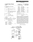
FIG. 7 is a How diagram of another detailed operation of a
damper control system 10 Which may begin at start block 101
and proceed to a symbol 102 Where a question about a damper
request is asked. If there is not a damper request, then a return
to the entry of symbol 102 may be made. If the ansWer is yes
the energy storage component comprises one or more
items comprising a capacitor or a battery; and
the energy storage component is capable of storing electric
energy su?icient to operate a damper assembly.
4. The system of claim 1, Wherein:
the controller is for providing a control signal to the damper
control component, based on inputs comprising energy
storage component status, a damper position signal, or
an appliance need for heat; and
the damper control component is for outputting a damper
drive signal in accordance With the control signal.
5. The system of claim 4, Wherein the damper control
component is connected to a damper assembly.
6. The system of claim 5, Wherein the damper assembly
comprises one or more damper position detectors for provid
to the question in symbol 102, then the operation may proceed
to a block 103 Where a damper is driven. The operation may
proceed further on to a symbol 104 Where a question of
Whether a ?rst end sWitch Was made or not. If an ansWer is no,
then the operation may return to block 103 to drive the
damper. If the ansWer is yes, then the operation may start a
timer at block 105. Then the operation may proceed to pro
vide PWM to the damper drive at block 106. From block 106,
the operation may proceed to symbol 107 Which asks the
question Whether the second end sWitch Was made. If an
ansWer is no, then operation may proceed to symbol 108 to
ask a question Whether the timer had expired. If an ansWer is
no, then the operation may proceed to block 106 to continue
to provide PWM to the damper drive. If the ansWer is yes to
ing the damper position signal.
7. The system of claim 5, Wherein the damper assembly
comprises:
20
an electrical mover connected to the damper control com
ponent;
the question in symbol 1 08, then the operation may proceed to
a damper connected to the electrical mover; and
block 109 to increase a PWM duty cycle and then go to block
105 to start the timer. The timer may track the expected time
it takes to sloW the damper doWn and coast to the end sWitch
a position indicating mechanism proximate to the damper;
and
25
position. When the timer expires, it is assumed the damper is
moving too sloWly or even has stopped. The PWM may be
increased to speed up the damper slightly so it reaches the end
sWitch sooner. If the ansWer to the question at symbol 107 is
yes, then the operation may proceed to stop the damper drive
30
at block 110 and go to a symbol 111 Where a question Whether
the second end sWitch Was made. If an answer to the question
and the operation may return to block 103 to restart the
35
damper position signals from the position indicating mecha
hypothetical or prophetic nature although stated in another
manner or tense.
40
at least one illustrative example, many variations and modi
?cations Will become apparent to those skilled in the art upon
45
1. A damper control system for a fuel burning appliance,
by the controller more in accordance With a signal from
50
a poWer source;
the damper drive signal comprises the pulse Width modu
source;
lation component.
12. The system of claim 11, Wherein the pulse Width modu
lation component is adjusted as the damper approaches a
an energy storage component connected to the poWer man
agement component;
a damper control component connected to the energy stor
destination position.
age component; and
a controller connected to the poWer management compo
60
the energy storage component is for storing electric energy
from the poWer source.
poWer source comprises one or more items comprising a pilot
light for igniting a ?ame, a ?ame, ambient light or a bulb.
13. The system of claim 4, Wherein:
the control signal comprises a pulse Width modulated com
ponent as needed; and
the pulse Width modulation component has a duty cycle
Which is adjustable.
14. The system of claim 1, Wherein:
the poWer source comprises a heat-to-electric poWer con
ver‘ter or a light-to-electric poWer converter; and
2. The system of claim 1, a source of heat or light for the
the energy storage component;
the damper control component is for outputting a damper
drive signal to the electric mover; and
a poWer management component connected to the poWer
nent and the damper control component; and
Wherein:
mechanism; and
the pulse Width modulation component has a duty cycle
Which is adjustable.
11. The system of claim 10, Wherein:
the pulse Width modulation component is further generated
What is claimed is:
comprising:
the energy storage component is for further providing
poWer to the damper control component;
a pulse Width modulation component of the control signal
is generated by the controller in accordance With a
damper position signal from the position indicating
reading the present speci?cation. It is therefore the intention
that the appended claims be interpreted as broadly as possible
in vieW of the prior art to include all such variations and
modi?cations.
has a polarity Which is reversible by the damper control com
ponent as directed by the controller in accordance With
nism.
10. The system of claim 7, Wherein:
In the present speci?cation, some of the matter may be of a
Although the invention has been described With respect to
ing one or more damper positions and for providing a
damper position signal indicative of the one or more
damper positions as an input to the controller.
8. The system of claim 7, Wherein the controller is for
controlling poWer via the damper control component as a
damper drive signal to the electrical mover to control a posi
tion of the damper.
9. The system of claim 8, Wherein the damper drive signal
is no, then the PWM duty cycle may be reduced at block 112
damper drive procedure. If the ansWer to the question in
symbol 111 is yes, then the operation may end at block 113.
Wherein the position indicating mechanism is for indicat
the heat-to-electric poWer converter comprises one or more
65
ther'mopiles; and
the light-to-electric poWer converter comprises one or
more solar cells.
US 8,632,017 B2
9
10
if the damper goes beyond the particular position accord
15. The system of claim 1, wherein the power management
component is for managing electric poWer going from the
ing to the sensor, then the damper control component
provides reverse drive signals to move the damper in an
opposite direction or provides drive signals to move the
poWer source to the energy storage component.
16. A damper control device comprising:
damper in the same direction to approach the particular
a poWer converter;
an electric energy storage component for receiving poWer
from the poWer converter;
a damper control component for controlling a ?oW through
a ?ue of a fuel burning appliance; and
a poWer management component for controlling the poWer
from the poWer converter to the electric energy storage
component and for controlling poWer from electric
position.
21. A control system for a damper comprising:
a poWer converter;
a poWer management component connected to the poWer
10
agement component;
a damper control component connected to the energy stor
energy storage component or the poWer converter to the
age component; and
damper control component.
a controller connected to the poWer management compo
17. The device of claim 16, Wherein the fuel burning appli
nent and the damper control component; and
Wherein:
ance is a Water heater.
18. The device of claim 16, Wherein the energy storage
component is capable of storing electric energy su?icient to
the energy storage component comprises one or more
items comprising a capacitor or a battery;
operate the damper control component.
19. The device of claim 18, Wherein:
20
the damper control component controls the ?oW through
the ?ue With drive signals to a damper assembly; and
the damper assembly comprises:
a damper;
a electrical mover connected to the damper; and
a sensor for indicating a position of the damper.
20. The device of claim 19, Wherein:
25
a pulse Width modulation component of the control signal
a request to the damper control component to move the
30
assembly;
if the damper has approached the particular position
according to the sensor, then the damper control com
ponent provides cease signals to stop movement of the
damper; and
is generated by the controller for the damper control
component in accordance With a damper position signal
from a position indicating mechanism proximate to a
damper; and
according to the sensor, then the damper control com
ponent continues to provide drive signals to the damper
the poWer converter provides electrical poWer converted
from heat or light to charge the energy storage compo
nent; and
the energy storage component has su?icient capacity to
store energy to operate a damper assembly.
22. The system of claim 21, Wherein:
the damper control component is for providing a control
signal to the damper assembly to control a position of a
damper of the assembly;
controlling a damper comprises:
damper to a particular position; and
the damper control component providing drive signals to
the damper assembly to move the damper;
if the damper has not approached the particular position
converter;
an energy storage component connected to the poWer man
35
the pulse Width modulation component has a duty cycle
Which is adjustable.
23. The system of claim 21, Wherein a source of heat or
light for the poWer converter comprises one or more items
comprising a pilot light for igniting a ?ame, a ?ame, ambient
light or a bulb.