1
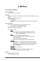
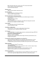
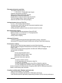
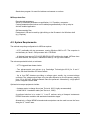
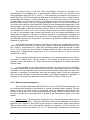
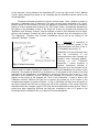
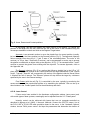
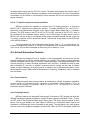
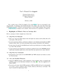
MPScope User's Guide
Version 1.1
April 2006
Quoc Thang NGUYEN
Physics Department, UCSD
[email protected]
DISCLAIMER
The programs described in this manual are available "as
is". The author takes no responsability in personal injury,
loss of data, material or time that could result from using
MPScope.
Please report bugs or suggestions to:
[email protected]
Copyright © Quoc Thang NGUYEN, 2005-2006. All Rights Reserved.
INTRODUCTION
4
A. MPScan
A.1. Summary of features
A.2. System Requirements
A.3. Installation
A.4. Hardware connections
A.4.1. Original Kleinfeld configuration
A.4.2. Other microscope hardware configurations
A.4.3. Connecting optional equipments
A.5. Using MPScan
A.5.1. Starting and Exiting MPScan
A.5.2. Login
A.5.3. Setting the hardware configuration
A.5.4. Choosing a scan configuration
A.5.4.1. Movie
A.5.4.2. Stack
A.5.4.3. Fast Stack
A.5.4.4. Line Scan
A.5.4.5. Region Scan
A.5.4.6. Starting and stopping a scan
A.5.4.7. Frame rotation and zoom
A.5.4.8. Acquisition parameters
A.5.5. Display
A.5.6. Saving data to a file
A.5.7. Scan configuration.
A.5.8. Saving and retrieving a configuration
A.5.9. X-Y-Z Control
A.5.10. Waypoints
A.5.11. Digital Stimulator
A.5.12. Analog Stimulator
A.5.13. Real-time Pixel Histogram window
A.5.14. Real-time Averaging window
A.5.15. Real-time ROI average intensity plot
A.5.16. Analog inputs
A.5.17. Controlling motorized micromanipulators.
A.5.18. Laser control.
A.5.19. Z- objective lens piezo electric positioner.
A.6. ActiveX Automation Features
A.6.1. Server Features
A.6.2. Scripting Features
A.6.3. Automation Reference
A.6.3.1. Predefined objects
A.6.3.2. ActiveX Automation Server Objects, Properties and Methods
A.6.3.3. ActiveX Automation Events
A.7. Known Bugs
1
B. MPView
B.1. Summary of features
B.2. System Requirements
B.3. Installation
B.4. Using MPScope
B.4.1. Opening a data file.
B.4.2. Viewing frames.
B.4.3. Examining the data file parameters
B. 4.4. Reviewing a data file
B.4.5. Opening a workspace
B.4.6. Copying and averaging frames
B.4.7. X, Y and Z projections.
B.4.8. Measuring pixel intensities.
B.4.9. Creating and Plotting Regions of Interest.
B.4.10. Exporting frames.
B.4.11. Creating video clips.
B.4.12. The Matlab Console
C. MPFile
C.1. System Requirements
C.2. Installation and registration
C.3. Using MPFile in Matlab
C.4. MPFile Reference
C.4.1. Instantiating MPFile
C.4.2. OpenMPFile Method
C.4.3. ReadParameter Method
C.4.4. ReadFrameData Method
2
INTRODUCTION
MPScope is a suite of programs to acquire and analyze data from ultrafast laser
scanning microscopes. MPScope was originally written for the setup developed in David
Kleinfeld's laboratory at the Physics Department, UCSD. Detailed description of this microscope
can be found in Tsai et al., 2002. However, MPScope can be used with other systems based on
identical scanners and data acquisition board. In particular, MPScope should be compatible with
the multiphoton systems developed by Winfried Denk (MPI Heidelberg) and Karel Svoboda
(HHMI).
MPScope is specifically designed for in vitro, ex vivo or in vivo systems
neurophysiology. It is a turnkey, professional-looking software with superior performance,
enhanced functionalities and intuitive user interface. Many of these advantages derive from
advanced features found in Windows 2000 and XP. MPScope consists of two programs,
MPScan and MPView and one utility, MPFile. These executable files are compiled and stand
alone, i.e. they do not require run-time libraries or specific programming environments to run.
MPScan is the acquisition program of MPScope. This program features:
- Several scanning modes, including fast frame, stack, fast stack, line scan and arbitrary region
scanning.
- X, Y and Z control including waypoints storage and recall.
- Real-time display of average values of regions of interest (ROIs).
- Live display of frames, averaged frames and frame pixel intensity histograms.
- Buit-in frame rotation and optical zoom.
- Simultaneous, gap-free acquisition and live display of up to two analog channels.
- A dual output analog stimulator and an 8-bit digital stimulator.
- Automated two-photon targeted patching for up to two electrode micromanipulators.
- An ActiveX scripting environment allowing users to write their own programs from within
MPScan in Microsoft Visual Basic Scripting Edition (VBScript).
MPView , the analysis program, can perform:
- Frame operations such as viewing frame, X, Y or Z stacking, averaging and linear
combination.
- Frame export, either as bitmap or multi-frame TIFF files.
- Region area or line statistics.
- Automatic object detection and ROI plotting.
- Extended support for Matlab via ActiveX Automation, including direct export.
- Creation of AVI movies.
MPFile is an ActiveX control designed to read MPScope data files. It is intended to be
used in programming environments such as Matlab or Visual Basic.
MPScope and its source code is available free of charge to researchers in academic
institutions. However, because of the preliminary nature of MPScope, this software package
should not be distributed without the consent of the author. Acknowledgement of the use of
MPScope in published work will be appreciated (Nguyen, Tsai and Kleinfeld, 2006; J. Neurosci.
Methods, in press). MPScope was developed thanks to the support of the National Institute of
Mental Health (MH 071566 to Quoc Thang Nguyen) and the Kleinfeld laboratory. Special thanks
to Philbert S. Tsai (UCSD) for testing and suggesting features, and to Chris Schaffer and
Nozomi Nishimura (Cornell University) for helpful discussions.
MPScope User's Manual
p.4
REFERENCES
For more information on the microscope hardware, refer to:
P.S. Tsai, N. Nishimura, E.J. Yoder, E.M. Dolnick, G.A. White and D. Kleinfeld "Principles,
design and construction of a two-photon laser-scanning microscope for in vitro and in vivo brain
imaging. Chapter 6 in In vivo optical imaging of brain function, R.D. Frostig, Ed., pp. 113-171,
CRC Press, Boca Raton (2002).
A PDF reprint of this book chapter is available in the Publications section of:
http://neurophysics.physics.ucsd.edu
More details on MPScan can be found in:
Q.-T. Nguyen, P.S. Tsai and D. Kleinfeld "MPScope: a versatile software suite for multiphoton
microscopy" (2006) J. Neurosci. Methods (in press).
Background on VBScript and COM in general:
Q.-T. Nguyen and R. Miledi "e-Phys: a suite of electrophysiology programs integrating COM
(Component Object Model) technologies". J. Neurosci. Methods (2003) 128, 21-31.
About VBScript:
Many books available in general bookstores deal with VBScript. Tutorials and references
can be found either on line at www.msdn.microsoft.com or can be consulted from the Help
menu in MPScan.
MPScope User's Manual
p.5
A. MPScan
A.1. Summary of features.
Multi-user capability:
Login window sets user preferences.
Hardware:
MPScope is compatible with Denk/Svoboda or Kleinfeld custom multiphoton microscope
designs
No specialized hardware necessary.
Typical configuration:
one Windows PC
one National Instruments data acquisition board interfacing two galvanometric
mirrors.
Frame acquisition:
Up to four video channels; two can be used as analog channels
+/- 20,10,5,2.5.1.25 V selectable input ranges
Frame size: 512 lines x 512 pixels, down to 100x10.
Dual direction scans for the fast mirror.
Five acquisition modes:
Movie:
512 x 512 pixels, 4 video channels with streaming: up to 5 fps
256 x 256 pixels, 4 video channels with streaming: up to 10 fps
30 fps+ for smaller frames
Stack:
Frame averaging possible for each section.
Linear or exponential automatic constant illumination control
time-series of stacks.
Option to close shutter between section.
Generates a scripting event each time a section is acquired.
Fast Stack:
200 microns in z-, 1 micron per section, 256 x 256 in 20 seconds.
600 microns in z-, 1 micron per section, 256 x 256 in 90 seconds.
1000 microns in z-, 1 micron per section, 256 x 256 in 240 seconds.
Linear or exponential automatic constant illumination control.
Time-series of stacks.
Line Scan:
as fast as 2.6 kHz per line.
Region Scan:
Select multiple rectangular, elliptic or polygonal regions.
MPScan will create a raster pattern and scan it.
Display:
Subframe selection with mouse.
Frame magnification on screen.
MPScope User's Manual
p.6
Black and white, false colors, custom color LUT for each video channel.
Frame overlay for targeted patch-clamping
On-line PMT offset correction.
Rotation, zoom:
While-you-scan software rotation and zoom.
Real-time display:
Real-time histogram of binned pixel values.
Real-time frame averaging window.
Real-time ROI (Region Of Interest) plotting:
Scrolling plot of average pixel intensity from user-defined regions of interest
during scanning.
Rectangular or elliptical ROIs
Tile/Overlay display.
User can define one ROI as background, other ROIs are background corrected.
ROI values are available for real-time scripting.
Laser control:
Front panel laser control for illumination power.
Can be controlled by scripts.
Acquisition configurations:
Keep a list of the 10 most recent configurations for fast settings.
Configurations can be saved and restored to/from disk.
X-Y-Z control:
Controls NEAT300 X-Y translation table controller or interfaces with Newport ESP-300
and Sutter MP-285 three-axes controllers
Move to X,Y or Z during acquisition.
Absolute or relative coordinates.
Waypoints can be named, stored (with an image of the frame) and returned to even
during frame acquisition.
Z- piezoelectric objective lens positioner (via one PCI-6711)
Supports the PiezoJena MIPOS 100 Z- piezoelectric fast positioner (up to 100 µm
displacement). Position controlled by an analog output from a PCI-6711 board.
Z- displacement (by fixed increment) can be done for every line scan or for every frame.
Digital stimulator:
Up to 8 independent digital TTL output lines.
1 ms resolution timer.
Two-level pulses of digital bits can be repeated for a finite or infinite number of times.
Pulses can be preceded by a prepulse.
Digital stimulation is triggered internally by frame acquisition or by user.
Digital stimulation patterns can be saved and restored from disk.
Pulse train generation:
Script control of the two General Purpose Counters (GPCTR) on the PCI-6110/6115E.
Can be used to generate digital pulse trains with 50 ns accuracy during scripts.
MPScope User's Manual
p.7
Electrophysiological acquisition:
Two analog channels inputs:
+/- 20,10,5,2,1 V selectable input ranges
Gap-free during frame acquisition
Always synchronized with video channels
Sampling rate reduced by decimation
Displays data in separate oscilloscope-like window
Two non-imaging modes: free-run and seal test
Seal test can also be done during imaging.
Analog stimulator (via one PCI-6711):
2 x 10 V, 12-bit analog channel outputs
Constant steps, trains (seal test) and incremental amplitude mode
Triggered by frame acquisition
Analog stimulation patterns can be saved and restored from disk.
Micromanipulator control:
for two motorized micromanipulators (Sutter MP-285)
Manual control of X,Y,Z and X-Z or Y-Z (diagonal) axes
Targeted patch-clamping mode
Overlay mode in display
Advanced file format:
Combined optical/electrophysiological data streaming during acquisition.
Advanced NTFS-based file system: 64KB sector writing for faster disk streaming.
Event-driven scripting:
Allows users to write their own programs to control the microscope.
ActiveX Scripting Integrated Development Environment: editor, debugger and type
library viewer
Users can write event-driven programs in the Microsoft VBScript language.
Interoperable with Matlab.
Events:
10 user-programmable buttons
when frame acquisition starts, ends
when section in stack is done
when new frames are acquired
Methods:
- to position X and Y mirrors,
- to add parameters and comments to data file
- to control X-Y-Z position,
- to send average pixel intensities from ROIs to Matlab in real-time
- to control multipurpose hardware timers on the data acquisition board
ActiveX component for Measurement Computing USB-1608FS USB-based acquisition
board for extra analog input channels.
Compiled, multithreaded, Windows optimized code
Object-oriented design, fully compiled.
Extensive use of threads and Microsoft COM-based architecture.
Uses Windows-specific application programming interfaces (APIs) to boost performance.
MPScope User's Manual
p.8
Stand-alone program. No need for Labview environment or run-time.
MPScope data files:
Experimental parameters:
Stores up 40 default parameters: magnification, X-Y-Z position, comments ...
Custom parameter name/values can be added programmatically to file by script or
ActiveX-enabled application.
Self-documenting files:
Parameters in file can be read by right-clicking on the file name in the Windows shell
(e.g. Explorer).
A.2. System Requirements.
The minimal computing configuration for MPScan requires:
- A PC, preferably with two processors, running Windows 2000 or XP. The computer in
our laboratory is a dual 1 GHz processor with 1 GB RAM.
- A National Instruments PCI-6110E OR PCI-6115E multifunction board. MPView does
not need Labview, but requires Traditional NI-DAQ (6.5 or up) to be installed.
The microscope should include, at minimum:
- A TTL-triggered laser beam shutter.
- Two galvanometric scan mirrors (e.g. Cambridge Technologies 6210) for X and Y
scans, with their MicroMax 670 driver boards.
- Up to four PMT detectors providing a voltage output usually via a current-voltage
converter. The voltage outputs have to be low-pass filtered at a cut-off frequency ranging
from 150 to 300 kHz. Multipole Bessel filters are preferred. Alternatively, a high-speed
photon integrator can be usedl
Optional microscope equipments include:
- A stepper motor to change focus (see Tsai et al. 2002 ; highly recommended).
- A Neat 300 X-Y translation table (see Tsai et al., 2002).
A preferred solution is to control X, Y and Z motions using a Newport Instruments
ESP300 three-axis controller with associated translation stages.
Alternatively, a Sutter MP285 microelectrode manipulator can be used to move the focus
along the X, Y and Z axes.
MPScope User's Manual
p.9
- Up to two National Instruments PCI-6711 analog output board. The Kleinfeld
configuration uses these boards to generate the X and Y scan voltages. MPScan uses
one board to output up to two analog voltages to drive stimulation inputs of
microelectrode amplifiers. The other board can be used to control additional optical
components such as a PiezoJena MIPOS 100 Z- objective positioning piezoelectric
actuator to provide a fast X-Z scanning capability. In case any of the extra boards are
used, they need to have their RTSI bus connected in hardware to the main board.
- Up to two MPC-285 motorized micromanipulators from Sutter Instruments for twophoton patch clamping.
Note: The rotator described in Tsai et al. (2002) is not needed by MPScope and can be
bypassed.
A.3. Installation.
Copy MPSCAN.EXE and SCRPT56.CHM to the directory of your choice.
A.4. Hardware connections:
Hardware connections depend on the way the microscope was built. If the microscope is
a copy of the one described in Tsai et al. 2002, refer to section A.3.1., otherwise follow
instructions in section A.3.2. MPScan can interface with other devices via the output lines of the
digital port on the PCI-6110E/PCI-6115E such as stimulators, via a serial port when using the
MPC-285 microelectrode positioner, or can be externally started via a TTL trigger. Refer to
section A.3.3 for wiring instructions.
A.4.1. Original Kleinfeld configuration.
Text in bold refers to mandatory hardware modifications to the Kleinfeld design.
Text in italic highlights optional modifications to accomodate new features.
Refer to fig. 1 for general wiring layout.
PCI-6110E or PCI-6115E:
Analog inputs:
AI0: goes to PMT1
AI1: goes to PMT2
AI2: goes to PMT3 or Analog Ch 1 (ex: cellular amplifier, etc...)
AI3: goes to PMT4 or Analog Ch 2
Analog outputs:
AO0: goes to X scan mirror driver (replaces output from PCI-6711)
AO1: goes to Y scan mirror driver (replaces output from PCI-6711)
Digital outputs:
DIO0: Stepper motor for Z-focus; Up (recommended)
DIO1: Stepper motor for Z-focus; Down (recommended)
DIO2: Digital stimulator output
MPScope User's Manual
p.10
Fig. 1. Connection layout of MPScan in the original Kleinfeld configuration. Items in italic are mandatory.
The PCI-6110E (or PCI-6115E) and the PCI-6711(s) have their RTSI buses tied together.
DIO3: Digital stimulator output
DIO4: originally reserved; Digital stimulator output
DIO5: originally reserved; Digital stimulator output
DIO6: originally reserved; Digital stimulator output
DIO7: originally reserved; Digital stimulator output
Digital input:
PFIx: (any PFI0 to PFI9 line) frame acquisition TTL trigger
PCI-6711: board 1:
Analog output:
AO0: not used or used as output (0..10 V) to drive the MIPOS 100
Z- objective positioner MOD input.
PCI-6711: board 2:
Analog output:
AO0: not used or used as Analog stimulator output channel 1
AO1: used as Analog stimulator output channel 2
Digital output:
DIO0: goes to laser beam shutter
If any PCI-6711 board is to be used, connect its RTSI lines to that of the PCI-6110E or
PCI-6115E. The RTSI bus will carry signals to synchronize all the boards.
COM Ports: COM port number assignement will depend on the configuration.
COMx: Danaher NEAT 300 X-Y controller
MPScope User's Manual
p.11
COMy: Sutter MP-285 motorized micromanipulator 1
COMz: Sutter MP-285 motorized micromanipulator 2
USB ports: A variety of optional peripherals can be connected to the USB ports
USB x: a PMD-1608 FS low -cost, 8-channel 16-bit data acquisition USB module.
MPScan provides an ActiveX library, allowing scripts to measure up to 8 different
analog voltages.
USB y: Sutter MP-385 USB-controlled micromanipulator 1
USB z: Sutter MP-385 USB-controlled micromanipulator 2
A.4.2.Other microscope hardware configurations.
MPScan is compatible with the Denk or Svoboda two-photon laser scanning microscope design
(Figure 2). Very little modifications are required to run MPScan. Refer to the previous section for
most connections. Differences are listed below.
Fig. 2. Connection layout of MPScan in the Denk or Svoboda scopes. Items in italic are mandatory. The
PCI-6110E (or PCI-6115E) and the PCI-6711(s) have their RTSI buses tied together.
PCI-6110E or PCI-6115E:
Digital outputs: any digital output (8 lines total) can be used to deliver a TTL compatible
signal. In addition, one digital output line can be used to control the laser beam shutter.
COM Ports:
One COM port can be used to connect to the MP-285 microelectrode positioner that
controls the X-Y-Z focus in some microscope realizations. In the Hardware configuration panel,
MPScope User's Manual
p.12
choose the Invert Z motion check box if the MP-285 moves the preparation rather than the
objective. Prior to starting MPScan, set the MP-285 microstep resolution to coarse (i.e. 0.2
µm/microstep).
A.4.3.Connecting optional equipments.
TTL trigger: The digital trigger uses a digital high TTL level on any PFI line to start a
scan.
Digital outputs. could be TTL low.
MPC-285 microelectrode positioner. MPScan can control up to two MPC-285
microelectrode positioners (Sutter Instruments) for automatic placement of sharp or patch-clamp
pipettes or to move the microscope field of view in the X-Y-Z directions. Connect the MPC-285
controller to an unused serial port on the PC. If no serial port is available, USB-serial port
converters can be used.
ESP-300 stage controller. MPScan supports the Newport ESP-300 three axes
controller to move the focus in the X, Y and Z directions. Connect the ESP-300 to the computer
and enter the appropriate information in the Hardware Configuration dialog box in MPScan.
Phil Tsai's laser control. Laser intensity can be controlled easily by connecting a cheap
servo mechanism ($25) used in model boats to the zero-order half-wave plate rotating device.
Laser light attenuation goes like the cosine of the plate rotation angle. Connect the command
input of the servo to the GPCTR1 Output of the PCI-6110E or PCI-6115E board. See the Laser
Control section in this manual.
Photon integrator. Photons detected by the PMTs can be integrated during the dwell
time of the laser above each pixel. A TTL-compatible pixel clock is available at the
SCANCLK_LINE output of the PCI-6110E or PCI-6115E.
Z- Axis objective lens positioner. Connect the AO0 output of the PCI-6711 board 1 to
the MOD input on the controller of the MIPOS 100.
A.5. Using MPScan.
A.5.1. Starting and Exiting MPScan.
Important: In the Kleinfeld configuration, if the X and Y scan signals (AO0 and AO1) go
through the rotator box before going to the mirror controllers, set the Tandem value to 2048 and
zero the offsets of rotator. Before starting MPScan, make sure that Labview is not running.
Exiting MPScan is done by clicking on the File/Exit menu item.
MPScope User's Manual
p.13
A.5.2. Login.
MPScan allows users to have different settings such as their private data directory.
Login can be either as Default User or by entering one's name.
Click on the MPScan icon to start. Only one copy of MPScan is allowed to run at any
time. A login window will be displayed. Enter the name of the user.
Each user has the following parameters, which are stored privately:
- last scanning configuration used.
- data directory.
- protocol directory (contains scanning configurations, analog or digital stimulation
- parameter files and scripts.
- position of some windows.
MPScan will display either the successful connection or the failure to detect hardware
such as the X-Y table. Click on OK.
The main window of MPScan includes several permanent windows:
- The Video window, which shows frames from up to two video channels.
- The Analog window, which displays incoming analog signals in an oscilloscope-like screen.
- The Histogram window.
- The Averaging window.
- The X-Y-Z control panel.
Some of these windows are minimized or hidden depending on the scanning
configuration.
If this is the first time you run MPScan, you need to setup the hardware configuration
first (see A.4.3).
A.5.3. Setting the hardware configuration.
Setting the hardware configuration is usually done the first time MPScan is run, after
which the configuration is saved permanently in the Registry. However, the harware
configuration can be changed anytime. You can also run the hardware configuration to attempt
to connect to a device that was disconnected when MPScan started.
Click on the Settings/Hardware Options... menu item to display the Hardware
Options dialog.
Make sure that
- the board indices match those found in the NI-DAQ Measurement and Calibration
program on the Desktop.
- the COM port and COM speed assignments are valid for the NEAT-300 translation
table or for any serial port-dependent devices (e.g. MP-285, ESP-300 etc...). See the Read
Delay instructions for the MP-285 below.
MPScope User's Manual
p.14
Click on OK or Cancel to resume. The Hardware Status dialog will be displayed in case
OK was chosen. Review the hardware status and click on OK. You can display the Hardware
Options dialog again if there was a mistake in hardware assignment.
Optional hardware:
- Motorized micromanipulators. Up to two computer-controlled motorized manipulators can be
added to the microscope system. Default transmission rate for MP-285 is 9600 bauds. In case
axes orientations of the micromanipulators are inverted, check the appropriate boxes. Many
computers are too fast to communicate with the MP-285 and could get erroneous position
information back from the controller. In this case, increase the Read Delay parameter until the x,
y, z positions are correct.
A.5.4. Choosing a scan configuration.
MPScan offers the following scan modes: Movie, Stack, Fast Stack, Line Scan and
Region Scan. These modes can be selected in the Video window in the Scan panel.
Fig 3. Configuration parameters for a
256 x 256 pixels frame.
Full frames are acquired by the following
modes: Movie, Stack and Fast Stack. The entire field
of view, determined by the maximal mirror deflection
voltage (Settings/Hardware Options... then
Mirrors panel) and the zoom factor (Viewer
window, Raster panel), spans 512 x 512 pixels. Any
rectangle inside this region can be scanned.
Cambridge Technology 6210 scanners provide a ±20°
deflection for input voltages spanning ±10V. Typically,
the maximal mirror deflection voltage is 2 or 2.5 V.
Zoom factors, adjustable from the Viewer window, can
be set between 1 and 10. The zoom factor reduces
the field of view by decreasing the mirror deflection.
Fig. 3 shows the layout of a 256 x 256 frame centered in the field of view. To scan the
grayed region in Fig.3, the appropriate values for X Offset, Y Offset, Frame Width and Frame
Height parameters have to be entered in the Configuration window (e.g. click on the
Configuration button, upper pane of the main window). A X Offset = 0, Y Offset = 0, Frame
Width = 512, Frame Height = 512 selects a frame equals to the field of view.
A.5.4.1. Movie.
In movie mode, MPScan can display up to 512 x 512 pixels from up to four imaging
channels. The frame rate will depend on the size of the frame.
Subframes can be chosen by clicking the mouse on a region and drawing a rectangle
over it. The Configuration dialog is then shown.
MPScope User's Manual
p.15
Pixel offset adjustment (when pixels are misaligned on screen)
MPScan uses dual direction scans to generate images. The laser beam is swept
in one direction to scan one line, then in the other direction to scan the following
line. There is a lag between the actual position of the mirror and the voltage
command, which is approximately 150 µs. Its exact value depends on your mirror
set .
When the lag is not compensated, objects in the image appear duplicated or have
"hairs" resulting from the misaligment of consecutive lines. To prevent this
effect, pixel offset adjustment must be done in all modes (except for region
scans) to compensate for the mirror lag. To adjust for pixel lag:
1. Set the rotation to 0 (Viewer window, Raster panel).
2. Scan a sample in movie mode.
3. Enter a value (for instance 150) in the X pixel line shift input box (bottom of the
Raster panel) and validate this value by clicking on the Apply button.
4. Observe the screen and try to move duplicate pixels on top of each other by
adjusting the X pixel line shift value. There should be little or no "hairs" caused
by misaligment of the forward and backward scans.
5. Enter the same value in the Y pixel line shift input box, validate and rotate the
scan by 90º. Adjust the Y pixel line shift value to get a sharp image.
Pixel shifts are stored in protocols. The future version of MPScan should
automatically align lines created by forward and backward scans using a
feedforward algorithm.
A.5.4.2. Stack.
When this mode is selected, the Stack panel is displayed in the Video window. A stack
consists of a number of sections. Each section is separated by a z-interval. A negative z-interval
indicates that the microscope focus is moved down after each section. A section consists of one
or several frames that are averaged. Stacks can be repeated for a number of times selected by
the user to obtain stack time series.
The stack mode can be selected only if the previous mode was Movie. The laser shutter
can be closed after each section to prevent overexposing the sample to laser light. The
corresponding setting can be set in the Hardware Configuration dialog.
When imaging inside tissue, MPScan can provide constant illumination as focus is set
deeper. At present, laser intensity control is provided by a servo mechanism (see section A.3.3).
The bottom box in the Stack control panel (main Viewer) features three input boxes to enter the
initial power (usually at the top of the stack), and the final power at a prescribed z- distance
(enter a negative value for stacks going down inside the tissue). The user can opt either to turn
constant illumination off, or use a linear or exponential relationship.
MPScope User's Manual
p.16
A.5.4.3. Fast Scan.
Fast Scan is a mode consisting of taking a movie at high frame rate while focus is
continuously changed. Select the Fast Stack from the Scan panel (go back to Movie first if the
Fast Stack is button disabled. The Fast Stack panel will appear. Select first by how much the
stack depth (enter a negative value to go from top to bottom), move the slider to select the travel
speed (this will give also the travel time) and the repeat count. If the repeat count is > 0, the
Fast Stack will repeat by going in the backward direction, then forward etc... until the number of
repeats has been reached. Frame size and frame rate can be adjusted in the Configuration
window.
Fast Stack can be used with laser intensity automatic control (see Section A.4.4.2).
Click on the Start Scan button to start Fast Scan. You can pre-arm streaming to disk by
clicking on the Start Streaming button beforehand. During a Fast Scan, the z- stepper control
panel (X-Y-Z Laser) will indicate that the stage is moving. At the end of a Fast Stack operation,
the z- focus is brought back to its original position, the laser power is set to its initial value (if
laser control of stack was enabled).
A.5.4.4. Line Scan.
Use the configuration dialog to set the pixel clock compatible with line scan. In Movie
mode, go to the View menu of the Viewer window and select Linescan Trajectory. A horizontal
line (yellow by default) will appear in the middle of the screen. This line shows where linescans
will take place. Optimize the placement of the line scan by zooming, rotating, ect... the desired
region in Movie mode first (i.e. place the cells of interest under the line scan). Select line scan
mode from the Scan panel in the Viewer window. The configuration dialog will appear. Frame
Height can be left at 512 lines per frame.
A.5.4.5. Region Scan.
To select a region scan, you must be in movie scan mode, with X and Y frame
offsets = 0 and Frame Width and Frame Height = 512.
Select the Region scan mode by clicking on the Region scan button in the Scan panel of
the Viewer window. A window will appear. Regions can be either rectangles, ellipses or
polygons. It's OK to draw regions that overlap. When regions overlap, pixels in the common
areas are scanned only once.
Choose to draw either a rectangle, ellipse or polygon. For the first two choices, position
the mouse, depress the left button, drag the mouse across the area to select and release the
left button. For polygons, click with the left mouse (i.e. depress-release quickly) on each vertex
of the polygon. To finish creating the polygon, click on the right button of the mouse.
The Configuration dialog will appear. Select an approprite pixel clock and click on OK.
You are now ready to scan.
MPScope User's Manual
p.17
A.5.4.6 Starting and stopping a scan.
Use the Scan/Start Scan, Scan/Stop Scan menu items in the main window or click on
the Start Scan button on the top left corner of the Video window to start or stop frame
acquisition.
Scans can be automatically stopped after a preset number of frames was collected. In
the Video window, Scan panel, unselect No frame limit and enter the number of frames in the
Stops after input box.
A.5.4.7. Frame rotation and zoom.
Frames can be rotated by an arbitrary angle from the Rotation group in the Raster panel
in Video window.
Similarly, frames can be magnified by reducing the amplitude of the scan pattern by a
factor shown in the Magnification group, Raster panel. Magnification results from reducing the
maximal deflection angle of the scan mirrors.
A.5.4.8. Acquisition Parameters.
Acquisition parameters such as frame rate, frame size and channel assignments can be
changed from the Configuration window.
A.5.5. Display.
The Video window displays frames either in gray levels, false colors or using a custom
look-up table (LUT). In the first mode, all pixels with values less than 0 are displayed as black,
all values larger than 2047 are displayed as red and mid-level level (1024) is shown in blue. To
change the color scheme, click on the various options of the "View/" menu of the Viewer
window. The "Overlay Channel 1 on Channel 2" menu item is useful during two-photon targeted
patch-clamping.
The pixel offset for each channel can be changed by selecting a value in the Channel 1
Channel 2, Channel 3 or Channel 4 input boxes on the Video window.
The latest frame can be saved as a bitmap by executing the View/Save as bitmap...
menu item in the Video window.
When a subframe is selected for scanning, frames may appear very small. Use the
Increase Zoom or Decrease Zoom menu commands under the Zoom menu in the Video window
to adjust the viewing size of the frame. This zoom is different from the Magnification factor in the
Raster panel.
A.5.6. Saving data to a file.
MPScope User's Manual
p.18
MPScan always maintains a data file ready. The name of the file is automatically chosen
by MPScan or can be overridden by clicking on the New File button or by choosing the
File/New/Data File... menu item in the main window. MPScope data files have a "MPD"
extension. The default name chosen by MPScan is YYMMDD_XXX.MPD where YY is the year,
MM is the current month, DD is the current day and XXX is a numeral incremented each time a
new data file is created.
Data can be saved to file anytime during acquisition by clicking on the Start Streaming
button on the Video window. Stopping streaming can be done the same way. Streaming can
start immediatly during scanning by setting Start Streaming before initiating frame acquisition.
When scanning ends, streaming ends automatically.
A new, empty data file is created each time a the scan configuration is modified by the
user. When the old data file is committed to disk, the file comments (main window menu bar)
are written to the file. Check for the change in the data file name in the caption of the Video
window and for a beep indicating that changes in the previous file were committed to disk.
MPScope data files are self-documenting by containing the following parameters:
- Type of data file: Movie, Stack, Line Scan, Progressive Line Scan or ROI Scan.
- X-Y position of the franslation table (in microns)
- Z- focus position
- File comments
TIP: To view all the file parameters outside MPView, for instance from Explorer, click on
the file icon with the right mouse button. A property sheet will appear. Select the "Custom" tab.
All parameters and their corresponding values will be listed.
Frame data in MPD files are stored in a custom binary format. Applications other than
MPView can use the MPFile ActiveX control described in this document to access data in MPD
files.
A.5.7. Scan configuration.
The Scan Configuration dialog allows users to set up various scan parameters such as
number of video and analog channels, gains etc... This window can be either automatically
displayed or explicitely called by clicking on the Experiment/Scan Configuration... menu item in
the main window.
MPScan maintains a list of the 10 previous configurations. To restore a previous
configuration, click on the Experiment/Previous Scan Configuration menu item.
A.5.8. Saving and retrieving a configuration.
MPScope User's Manual
p.19
Scanning configurations can be permanently stored on disk in a directory implicitely
specified by the user. See the File/Open/Configuration..., File/Save/Configuration..., File/Save
As/Configuration... menu items in the main window.
When MPScan is closed, the program will prompt the user to save the current
configuration if it was changed from the original one during the session.
A.5.9. X-Y-Z Control.
The X-Y-Z panel controls the X-Y translation table and the Z-stepper device. The remote
control style buttons are self-explanatory.
A.5.10. Waypoints.
A waypoint consists of a set of X, Y and Z coordinates that can be stored (alongside with
an image of the frame at that position) and recalled, even during scanning. Waypoints can be
stored sequentially by clicking on the Save Waypoint button (Waypoints pane, main window). A
meaningful description of the waypoint can be entered in the text box just above the Save
Waypoint button. Waypoint descriptions are listed in the X-Y-Z panes. The user can display the
image of the waypoint and can delete all the waypoints.
A.5.11. Digital Stimulator.
The digital stimulator is capable of delivering TTL pulses on the digital port of the PCI6110E or PCI-6115E at precise times with a resolution of 1 ms.
To set up the stimulation pattern, select the Experiment/Digital Stimulation... menu item.
A window is displayed. Some of the output lines are used by legacy devices. Select the
appropriate lines and stimulation times.
Digital stimulation can be armed before scanning or can be initiated before scanning by
clicking on the Start Digital Stimulation button in the main window. Stopping scanning
immediatly stops digital stimulation.
A.5.12. Analog Stimulator.
A.5.13. Real-time Pixel Histogram window.
The histogram window displays the count of binned pixel values in incoming frames. A
running histogram of pixel values in incoming frames is useful to diagnose potential problems.
MPScope User's Manual
p.20
Select the Windows/Real-Time Pixel Histogram Window... menu item in the Video window. This
option is only available in Movie mode.
A.5.14. Real-time Frame Averaging window.
A running average of incoming frames is useful when signals are noisy or weak. Select
the Windows/Real-Time Frame Averaging Window... menu item in the Video window. This
option is only available in Movie mode. Up to 15 frames can be averaged.
A.5.15. Real-time ROI average intensity plot.
Real-time plots of regions of interest is possible only in the Movie scanning mode. From
the viewer window, depress the Rectangular or Elliptical Real-Time Plot buttons. Select a
rectangular or elliptical ROI on the frame by clicking and dragging the mouse over a region of
interest. Once the left mouse button is released, a dialog window will appear. The ROI color in
the Plot window and whether the ROI is set as background can be selected by the user.
Each new region of interest will create a new subplot in the ROI Live Plot window. The
ROI Live Plot window will display the averaged pixel value of each ROI corrected with the value
of the background ROI for the appropriate channel (if such ROI was selected by the user).
When multiple channels are enabled, MPScan will ask if a given ROI should be
replicated in the other channels. The ROIs can be used to generate a real-time plot of FRET or
ratiometric calcium concentration.
A.5.16. Analog inputs.
Analog inputs can be visualized in the Analog window. These inputs have to be enabled
in the Configuration window. Up to two channels of analog inputs can be set up using the AI2
and AI3 inputs of the main acquisition board. These inputs are renamed 'Analog Ch 1' and
'Analog Ch 2'. To use the analog input channels, go to the Configuration window, enable the AI2
or AI3 inputs but uncheck the "Use as Imaging Ch" box. It is recommended to give the channels
a meaningful name and units. Because analog inputs usually do not require a high acquisition
rate, these signals can be subsampled by inputting a value in the "Data Points / Frame" input
box. This will correspond to an acquisition frequency calculated below.
Normally, analog inputs are displayed in the Analog window in an oscilloscope-like
manner during frame acquisition. However, it is possible to acquire these analog inputs without
scanning. Two analog acquisition modes independent of scanning are available.
The first one, called 'Free Run', allows viewing analog inputs in a scrolling display.
Sampling rate and maximal duration of the display ('Time Base') can be set by the user. The
sampling rate can be adjusted as low as 0.05 ms (corresponding to a sampling frequency of 20
kHz) or as high as 1 ms (1 kH) with increments of 0.1 ms. Start Free Run by clicking on the
button in the Analog Input window. The Time Base can be set between 1 s and 10 s.
MPScope User's Manual
p.21
The second mode is 'Seal Test' which automatically calculates the resistance of a
microelectrode or a membrane seal. A microelectrode amplifier is driven by one output of the
analog stimulation board (PCI-6711; see Fig. 1). The board has to be present in the computer to
enable 'Seal Test'. MPScan automatically determines if the amplifier is used in voltage-clamp or
current-clamp by checking if output commands are in mV and analog input are in pA or nA
(voltage-clamp), or if the output is in pA or nA and analog inputs are in mV (current-clamp). To
set up the units correctly, use the Configuration window to enter units and conversion factors
for analog inputs, and the Analog Stimulator window to enter the appropriate parameters for the
analog outputs. 'Seal Test' starts after the corresponding button is depressed and stopped when
the user clicks again on the button. MPScan outputs a 200 ms, 50% duty-cycle square pulse (50
ms of baseline at 0 mV or 0 nA, 100 ms at the user-selected level and 50 ms baseline at 0 mV
or 0 pA) via the selected output channel and records one or two channels depending on the
analog input configuration. The seal or electrode resistance is calculated by averaging and
subtracting the baseline values from the last 20 ms of the step interval. Negative values for the
user-selected levels can also be entered if, for instance, one wishes to measure the membrane
resistance of a given cell.
In all modes (scanning, Free Run or Seal Test), the display can be adjusted by the user.
Colors and grid lines can be set by selecting the 'Settings...' menu item under the 'Display' menu
title. To alter Y- magnification or Y- offset from the Analog window, select the channel to modify
('Ch 1' or 'Ch 2') then move the scroll bar to change the offset or click on the arrows to change
magnification. Y Magnification ranges from 1 to 32. To reset the offset to 0, click on the scroll
bar and type '0' (zero).
During scanning, analog inputs are acquired only if the scanning mode is set to 'Movie',
'Line scan' or 'Region Scan'. The time base (i.e. the duration of the X-axis for any analog
channel) is set to the duration of a frame. Each screen will display all the analog data taken
during a frame.
It is also possible to run a seal test while scanning is in progress in Movie or LineScan.
This mode is useful when making visual contact on a neuron. Start a scan then click on the Seal
Test button. This will temporarily stop scanning, initiate the seal test and restarts the scan. This
sequence is necessary to synchronize scan data and analog output. During the subsequent
scan, a seal test waveform is delivered every frame and the pipette resistance is displayed. In
this mode, the entire Seal test pulse lasts exactly one frame and has a 50% duty cycle.
A.5.17. Motorized micromanipulators.
Up to two Sutter Instruments MP-285 (and in the future, MP-385) micromanipulators can
be controlled either manually or automatically to perform two-photon patch-clamping. The user
needs to register the initial position of the pipette using the Calibration procedure and the
position of the targeted cell. Targeted patch-clamping is only possible in Movie mode. User
interface to control the micromanipulators is located in the "Manipulators" panel of the main
window.
Manual control: This mode allows positioning of the electrode anywhere along the four
axes of the micromanipulator. Clicking on the buttons will move the manipulator by a distance
specified in the "Increment" input box at a given speed. In coarse mode, speed cannot exceed
2900 microns/s, while in fine mode, speed is limited to a maximum of 1310 microns/s. For
motions across a fourth axis, select "X-Z" or "Y-Z". "Pipette Angle" corresponds to the actual tilt
MPScope User's Manual
p.22
of the electrode. During Motions the simulated LED at the top right corner of the "Manual
Control" panel changes from green to red, indicating that no commands can be issued to the
micromanipulator.
Two-photon electrode placement is done in several steps. Once a pipette is placed in
the setup, a calibration step is performed. The user can then move the pipette to a "Home"
position, which can be recorded. The user will register the coordinates of the cell of interest by
placing it in the crosshairs and clicking on the "Set Target" button. Automatically placement of
the pipette in the immediate vicinity of the target cell is done by successively activating the
"Approach" and "Descent" motions. Once the pipette is within a short distance from its target,
the user can manually "Contact" the cell by moving the electrode by a few microns at a time.
The "Approach", "Descent" and "Contact" parameters can be set up by clicking on the
respective "Settings..." buttons.
Calibration is necessary to
map the coordinate system of the
micromanipulator with that of the XY-Z translation device (Fig. 4).
Calibration must be performed each
time the orientation of the
micromanipulator axes changes (for
instance, after changing pipette).
Clicking
on
the
"Calibrate
distances..."
button
displays
a
Fig. 4. Calibration principle.
window. Calibration consists of
placing the tip of the electrode at four
different points in space (forming the summits of a cube) and registering the position of the
electrode. The pipette tip (filled with a fluorophore) is to be placed at the center of the field
(indicated by the intersection of crosshairs) by moving the field of view in the X, Y or Z
directions. Once calibration is done, MPScan can calculate the motions of the pipette with
respect to the position of the targeted cell. Click on the 'Calibration...' button to show a the
Calibration window. MPScan will ask first to position the pipette tip at the center of the
crosshairs and register its position (Position 1 in Fig 4). MPScope will then move the pipette to
the other positions and will ask to position the tip at the crosshairs of the screen using the
translation table and z-stepper controls, NOT with the micromanipulator motion devices. Once 4
points have been registered, MPScan can map any coordinate in the X-Y-Z space of the
microscope with a coordinate in the x-y-z space of the micromanipulator.
MPScope User's Manual
p.23
Fig. 5. Home, Descent and Contact positions
At this stage, the user can register the Home position of the pipette. To register the
position of the target cell, the user will move the cell at the center of the crosshairs using the
microscope translation controls and click on the Register Target button.
Approach is an automatic motion to move the pipette from its current position (usually,
but not necessarily the Home position) to the Descent position (Fig. 5). The Approach trajectory
follows straight lines along the X, Y and Z axes of the micromanipulator. The order of the
motions (i.e. X first, then Y and finally Z motions) can be programmed in such a way to prevent
the pipette to collide with an object such as the objective. In Fig. 5, Z is executed before Y and Z
motions to prevent the pipette from colliding with the objective. To execute Approach, click on
the 'Approach' tab.
The Descent trajectory (Fig. 5) is a motion that follows a straight line in the X-Z or Y-Z
plane from the Approach position to the Contact position at an angle determined by the "Pipette
Angle". Typically, "Descent" will correspond to the motion of the pipette inside the tissue before
it reaches the cell of interest. The "Descent" phase will stop before the target by a distance
specified by the user in the Descent settings.
Final Contact with the cell (Fig. 5) is controlled by the user, typically by monitoring the
access resistance of the patch-clamp pipette or by measuring the potential. Click on the up or
down buttons in the 'Contact' panel to move the electrode up and down.
A.5.18. Laser Control.
If laser control was enabled in the Hardware configuration window, laser power (and,
with certain types of laser systems, wavelength) can be adjusted from the X-Y-Z Laser panel.
Intensity control can be achieved with lasers that are not computer-controlled as
described in Nguyen et al. (2006) J. Neurosci. Methods. Connect the GPCTR1 output line of
the PCI-6110E or PCI-6115E main acquisition board to the servo. In the "Hardware Options"
window, choose "Phil's power control" and input the parameters that determine the duration of
MPScope User's Manual
p.24
the pulse width coming from the GPCTR counter. The pulse width controls the rotation angle of
the servo mechanical output. Because of hysteresis in this arrangement, two sets of parameters
are needed, one for rotation in one direction (Power Increase) and one for the reverse direction
(power decrease).
A.5.19. Z- objective lens piezo electric positioner.
MPScan provides the capability to perform fast X-Z imaging thanks to a PiezoJena
MIPOS 100 Z- objective lens piezoelectric position. To enable the MIPOS 100, one PCI-6711
board has to be installed and assigned as the Optics Control Board (Main menu -> Hardware
Options). The RTSI buses of the PCI-6110E (or PCI-6115E) and that of the PCI-6711 have to
be connected. In the Hardware Options dialog, in the Z Piezo page, the type has to be set to
MIPOS 100. Set the list box to the desired analog output command channel that will control the
Z- position. In general, AO0 is the default channel. Connect this analog output to the MOD input
of the MIPOS controller.
Typical parameters in the Configuration panel include 'From z', 'To z' and Increment. For
instance, corresponding values of 0, 100 and 10 indicate that the Z- actuator position will start at
0 ms, end at 100 µm and incremented at either every line or frame by 10 µm.
A.6. ActiveX Automation Features.
MPScan was designed from its inception to be programmable by end-users with the
shortest learning curve and the maximal efficiency as possible. This ruled out forcing the users
to delve into Matlab source code or to modify a Labview program. The widespread usage of the
ActiveX technology in many Windows applications such as Excel or Matlab provides a great
deal of flexibility to the user. In addition, numerous ActiveX controls can be used in ActiveX
scripts to control hardware. An ActiveX control to interface with a USB-based 8-channel, 16-bit
data acquisition board (PMD-1608FS; Measurement Computing, Middleboro, MA) is available
from the author.
A.6.1. Server features.
MPScan exposes many internal objects and methods to ActiveX Automation controllers.
In other words it is quite easy to write a program in Visual Basic, Object Pascal or C/C++ to
control the microscope via MPScan. Refer to section A.5.3. for description of ActiveX
Automation objects in MPScan.
A.6.2. Scripting features.
MPScan features an Integrated Development Environment (IDE) hosting the Microsoft
VBScript language interpreter available in Internet Explorer (Nguyen and Miledi, 2003). To start
the IDE, click on the Experiment/Show Script Editor menu. The Script window consists of three
panels. The left one displays the Type Library of MPScan (i.e. information about objects and
procedures of MPScan that can be controlled by the script). The right panel is the code window
and the bottom one displays messages from the IDE. When the IDE is displayed, additional
MPScope User's Manual
p.25
buttons are shown at the bottom of the main window. These buttons allow starting and stopping
the current script, or triggering various actions. The caption on these buttons can be changed
(Script /Rename Buttons... menu item).
The default script language is VBScript from Microsoft, which is a subset of Visual Basic.
VBScript programs are composed of an Initialization body, similar to the main() function in a C
program, and event handlers which are called when a particular event has taken place.
It is a good idea to declare all global variables in the script in the Initialization section of
the script (e.g. Dim MyVariable1, MyVariable2 etc... The Initialization section is executed
immediatly after the script is started, then the script interpreter waits for events to occur. An
event is triggered when scanning starts, scanning ends, when a section is done or when a
button is clicked.. Each time a event happens, the code associated with this event is executed.
A program terminates when the user clicks on the Stop Script button or calls the EndScript
procedure.
Script source code can be saved to disk, recalled or printed. Browser/Open Type
Library... opens a type library for browsing. If Matlab is installed in your computer, try opening
for instance C:\MATLAB6p5\bin\win32\mlapp.tlb. Browser\Load Reference reloads
the type library of MPScan.
Example: Enter the following line in the main window:
MsgBox "Hello World"
Click on the Start Script button. A window with the text "Hello World" should appear.
Click on OK, then on Stop Script. To enter code for a given event, select the event from the list
box on the Script Editor window and enter the event code.
Typically, the main section will contain initialization code. The script will then wait for
events.
On-line help. The editor features an on-line help. Highlight a VBScript keyword and click
on F1 to open the VBScript help file. For complete help, click on the Help/VBScript Reference...
menu item.
Saving, retrieving and printing scripts. Scripts can be saved to files, reloaded from
data files or printed. See the File menu in the main window.
A.6.3. Automation reference.
A.6.3.1. Predefined objects.
The MPScan Automation Server defines and instantiates the following global objects:
MultiPhoton, MPLaserShutter, MPXYTable, MPZStepper
These names are part of the namespace of scripts. It is unnecessary to reference them in order
to invoke their methods or access their properties, i.e.:
MPScope User's Manual
p.26
MultiPhoton.LoadProtocol "myProtocol.PRT"
can be abbreviated as:
LoadProtocol "myProtocol.PRT"
In addition, MPScan can control the two General Purpose Counters (GPCTR) available
in the PCI-6110E/PCI-6115E board. These counters are represented by the obejcts GPCTR0
and GPCTR1. Shortcut methods and properties are available to generate TTL-compatible pulse
trains on the GPCTR0 and GPCTR0 outputs. Other, more general methods can provide script
writers with finer control over counter functions. These methods are identical to those in the NIDAQ application programming interface.
A.6.3.2. ActiveX Automation Server Objects, Properties and Methods.
Browse the Type Library (Left panel of the Script Window) for information on objects,
properties and methods.
MultiPhoton:
AddFileProperty
Adds a custom file property / value pair to the Summary Information stream of a
data file. This pair can be subsequently read either in MPView or can be
inspected by clicking the file icon with the right mouse button, then selection
Properties..., and the Custom tab.
Syntax: AddFileProperty propname, propvalue
where propname and propvalue are strings
Example:
AddFileProperty "Laser Power", CStr(laserPower)
FileComments
Laser_Shutter
Predefined object
LoadConfiguration
SetLaserBeamTo
Syntax: SetLaserBeamTo X, Y
where X and Y are integer values from 0 to 511. This command sets the laser
beam to absolute position X and Y by moving the mirrors.
StartDigitalStim
StopDigitalStimulation
StartScan
StopScan
StartStreaming
StopStreaming
SetDigitalBit
MPScope User's Manual
p.27
NewDataFile
Syntax: NewDataFile or NewDataFile <filename>
Ex: NewDataFile "c:\mydata\myfile.mpd"
The <filename> argument is optional. If omitted, MPScan chooses a default
filename (yymmdd_xxx.MPD, where yymmdd is the year, month and date using
two numerals, xxx is an index from 1 to 999).
Wait
XY_Table
Predefined object
Z_Stepper
Predefined object
LastFrameIndex:
The index of the last frame acquired.
Matlab:
A predefined instance of Matlab.
Scanning:
0 if not scanning, 1 when scanning
DoEvents:
The analog of Visual Basic DoEvents. Use it with Scanning to wait for the
completion of a scan like:
' Waiting for a scan to finish
While Scanning <> 0
DoEvents
Wend
YScanOffset:
Reads or sets the the value of the Y offset of the scan pattern.
EndScript
Immediatly ends the script. Same as if user would end script manually.
Use this procedure to terminate a program.
GPCTR0
General purpose counter 0
GPCTR1
General purpose counter 0
Laser
Laser control for wavelength and power.
WriteMessage
Syntax: WriteMessage message_string
Writes a message string to the Message window of the Script Editor.
MPLaserShutter:
Close
Open
MPScope User's Manual
p.28
MPXYTable:
MoveToXY
Syntax: MoveToXY X, Y
Tells the X-Y translation table to go to absolute positions Xand Y (in microns).
ShiftByXY
Syntax: ShiftByXY deltaX, deltaY
Tells the X-Y translation table to shiftt by deltaXand deltaY (in microns).
XPosition
Reads the current X position of the X-Y translation table.
YPosition
Reads the current Y position of the X-Y translation table.
XYCommand
Syntax: MoveToXY command_string
Sends a command string to the XY controller (usually via the serial port).
XYSpeed
Syntax: XYSpeed = new_speed
Sets the speed of the XY controller. 1 ≤ new_speed ≤20
MPZStepper:
ZPosition
MoveToZ
ShiftByZ
ZSpeed
Syntax: ZSpeed = new_speed
Sets the speed of the Z stepper. 1 ≤ new_speed ≤20
Matlab:
Start
Starts the predefined instance of Matlab.
PutROI
Puts the values of an ROI trace (identified by its index from 1 to the number of
ROIs) into a named Matlab array.
Execute
Executes a Matlab command.
GPCTR:
The GPCTR object controls one of the General Purpose Counters (GPCTR) on the PCI6110E/PCI-6115E. The default operation is a pulse train with duty cycle set by the
Counter_1 and Counter_2 values. However, finer control (including other operating
modes) are possible. Refer to the NI-DAQ reference for GPCTR operations and function
parameters.
MPScope User's Manual
p.29
Reset:
Stops the current operation of the counter.
Counter_1:
Write-only. The duration of the first interval in a train. A multiple of the time base
(50 ns = 20 MHz). From 1 to 224-1.
Counter_2:
Write-only. The duration of the second interval in a train. A multiple of the time
base (50 ns = 20 MHz). From 1 to 224-1.
Start:
Prepare and arms the counter.
SelectSignal
SetApplication
Control
Example:
' This script snippet generates a pulse train
' on the GPCTR 0 output line.
With GPCTR0
.Reset
.Counter_1 = 1000 ' 50 microseconds for first interval
.Counter_2 = 10000 '500 microseconds for second interval
.Start
End With
MPLaser:
Power:
Adjustable from 0 to 100 (in %).
Wavelength:
A.6.3.3. ActiveX Automation Events.
Code can be automatically executed by MPScan in response to the following events:
- One of the 10 user-available buttons at the bottom of the main window has been clicked.
- OnAcquisitionStart. Triggered immediatly before frame acquisition starts.
- OnAcquisitionEnd. Triggered when frame acquisition has ended.
- OnSectionEnd. Triggered each time a new section in a stack was completed.
- OnNewFrames. Triggered each time frames have been received. You can use this event to
send ROI values to Matlab in near-real time.
To perform an action during an event, add code to the appropriate event handler. Be
sure to check the Enable Event check box in the Script Editor.
MPScope User's Manual
p.30
A.7. Known Issues and Bugs.
1. Stack averaging with count of 1 produces inverted frames.
Description. If stacks are performed with an average of 1, alternate frames are shown inverted.
Fix. Use an even average count. This bug is being investigated.
2. Very rare random crashes during acquisition due to network activity.
Description. The computer displays a "Blue Screen of Death" or resets during acquisition. This
happens extremely rarely and is due to a bug in the National Instruments driver. This bug not
only affects MPScan but also Labview programs.
Fix. During acquisition, it is recommended to disconnect the computer from the network.
3. Error message after creating a new directory.
Description. When creating a new data file, if the user creates a new directory in the file
creation dialog and selects it to place the new data file, a Windows error message appears.
Fix. Disregard the wrongful error message and select the directory anyway.
MPScope User's Manual
p.31
B. MPView
MPView is the analysis program of MPScope. It is designed to let users to review and
analyze their files efficiently. Further frame post-processing is eased by the ability to rapidly
export raw or processed frames either to Matlab or ImageJ.
B.1. System Requirements.
MPView requires a PC running Windows 2000 or Windows XP. If desired, MPView can
export frames directly to Matlab (The Mathworks, Natick, MA).
B.2. Installation.
Copy MPVIEW.EXE to the directory of your choice.
MPView is designed to interface seamlessly with Matlab. By default, MPView tries to
start Matlab from the same computer it is running from. However, it is possible to run Matlab on
another computer using DCOM (Distributed COM). You will have to set DCOM on the server
and client sides. Refer for instance to:
http://www.opcactivex.com/Support/DCOM_Config/DCOM_ClientSettings/dcom_clientsettings.html
for instructions on setting up DCOM.
B.3. Using MPView.
B.3.1. Opening a data file.
From MPView. After starting MPView, click on the Open button on the main tool bar or
on the File/Open File... menu item. Select a MPScope file (extension *.MPD for MPscope
Data file) and Click OK on the button of the Open Data File dialog box. You can open only
one instance of a data file.
From the Shell. Single or multiple data files can also be opened by MPView by dragging
and dropping their icons (from an Explorer file directory window or from the Desktop) in the main
window of MPView.
MPView associates MPD files with MPView by setting registry values the first time it is
run. Next time Windows is restarted, MPD data files will have the same icon as MPView.
Clicking on the file icon will start MPView and immediatly open the data file.
Note: If MPScan is running, MPView cannot open the current data file of MPScan.
MPScope User's Manual
p.32
B.3.2. Viewing frames.
Each data file is associated with one or several Viewer windows. To add a new Viewer,
click on the View/New Frame Viewer menu item of a Viewer. Each viewer has navigation
buttons (<<, <, Stop, >, >>) corresponding to menu items under the Frame menu. To go to the
first frame, last frame or a particular frame in the file, click on the Frame/First Frame,
Frame/Last Frame or Frame/Go to Frame... menu items. Keyboard shortcuts include:
Left-Arrow: Next Frame
Right Arrow: Prev Frame
Ctrl+G: Got to Frame
The menu item Frame/Comments... allows users to add a comment to the current
frame.
Users can choose to display frames either in Gray Scale (default), in False Colors or
using custom colors (View/Gray Scale, View/False Colors, View/Custom Colors).
Custom color schemes are selected using the dialog shown under View/Custom Colors
Look-Up Table. Pixel values below 0 are shown in green or black in gray scale or false
colors, respectively. Frames can be enlarged or reduced (View/Increase Zoom,
View/Decrease Zoom)
B.3.3. Examining the data file parameters.
To examine the data file parameters, click on the File/File Information... menu item.
B.3.4. Reviewing a data file.
Multiple independent views of the same data file can obtained by selecting the View/New
Frame Viewer menu item.
Commands include fast forward and reverse, next frame, previous frame and go to
frame.
B.3.5. Opening a workspace.
Users can create workspaces (File/New Worskpace File), which are groups of frames
residing in memory. Workspaces are usually created to store results from frame operations.
Workspaces are essentially similar to data files, at the exception that they contain frame data
from only one channel. Workspaces can be saved as data files.
B.3.6. Copying and averaging frames.
MPScope User's Manual
p.33
Destination for these operations must be an empty workspace.
B.3.7. X, Y and Z projections.
X, Y and Z maximal projections can be performed on contiguous frames. The result is
stored in a workspace. If the operation fails due to a problem with frame size, create a new
(blank) workspace and try again with the new workspace.
B.3.8. Applying gamma correction.
Destination for these operations must be an empty workspace.
B.3.9. Measuring pixel intensities.
To obtain a pixel statistics of an area, click on the Operations/Area statistics menu item,
and select a region to analyze by clicking and dragging the mouse above the region. A dialog
box will appear with the statistics of the area.
To obtain a pixel intensity plot of across a line, click on the Profile button on the Viewer
then draw a line by clicking the mouse and dragging it and releasing the mouse. A Profile
window will appear.
B.3.10. Creating and plotting regions of interest.
Three types of regions of interest (ROIs) can be created. Users can select either a
rectangular or an elliptical ROI with the mouse by clicking and dragging. In case two channels
were acquired, MPView will ask if the same region should be created in the adjacent channel.
Once a rectangular or elliptical ROI is created, MPView will query for the starting frame
and ending frame of the plot. A plot of pixel averages across frames will be created.
Alternatively, threshold-based objects can be detected automatically by MPView. Once
objects are classified, users can double-click on them to generate a plot. In case two video
channels exist in the file. the user can create the same ROI in the opposite channel.
Plot values can be transferred to the clipboard as a character-based, TAB-separated
array of frame index - ROI average pixel value pairs. Such arrays can be easily pasted into
other programs.
B.3.10. Exporting frames.
MPScope User's Manual
p.34
MPView can directly export series of video frames directly into a local or remote instance
of Matlab. Alternatively, MPView allows saving individual frames as bitmap files. Also, MPView
can save groups of frames in a multi-frame TIFF file. This kind of file can be opened directly in
ImageJ. These operations are accessible from the Viewer menu bar.
Exporting frames as bitmaps. Saved bitmaps are 24-bit RGB.
Exporting frames in Matlab. Exported frames are exported as arrays of double. To export
frames to Matlab, from a viewer, select the Operations/Export Frames to Matlab... menu item. In
the Export Frames to Matlab dialog box, select the channel (if two channels are in the file), the
starting frame and ending frame. Each frame will be exported to a different Matlab array, which
name will be Base Frame Name_Extension (ex: Frame_13). The Extension is automatically
incremented for each frame. There is no need to start Matlab (with main window button or
Matlab menu) before exporting frames, as this will be done automatically.
Exporting frames to TIFF files. MPView can save consecutive frames of a given video channel
into a multi-frame TIFF file. MPView maps native 12-bit encoded pixel values from 0 to 2047
into 16-bit values ranging from 0 to 65535. If negative native values are encoutered in the
frame(s), they are converted to 0 and the user is notified of the truncation. The
ImageDescription tag of each fram contains additional information such as frame rate, X, Y and
Z positions of the stage etc...
B.3.11. Creating video clips.
MPView can create uncompressed AVI video files from series of frames. The original
frame rate can be changed to slow down or accelerate the movie during replay.
B.3.12. The Matlab Console.
Matlab can be controlled from within MPScope via the Matlab console (Main window,
Matlab/Start Matlab... menu). MPView prompts the user to use either a Local Server
(installed on the current machine) or a Remote Server, located on another machine belonging
to a Local Area Network. The latter option requires (i) Matlab to be installed on the remote
computer (ii) knowing the name of the remote computer (iii) setting up DCOM on both
machines. This step is mandatory but not trivial. Refer to instructions available on the Web for
system administrators.
Once Matlab is running, enter commands from the caret prompt.
Users wanting to use Matlab (Mathworks, Natick, MA) to analyze frames have two
possibilities. They can export frames directly to an instance of Matlab either running locally or on
a remote server, or use a library to open and read MP files. The library is packaged into an
ActiveX DLL called MPFILE.DLL (see chapter C in this document).
B.3.13. Binary Frame Operation.
MPView supports creating a linear combination of 2 frames. The output of the operation
MPScope User's Manual
p.35
can be described as result = gain1.Frame1 + gain2.Frame2 where gain1 and gain2 vary
between -1 and 1. To perform a binary operation, open the file(s) containing Frame1 and
Frame2, then create an empty workspace (menu or Ctrl-N). Select from any Viewer menu
Operations/Binary Frame Operations...
Select the file or workspace, the frame index and the gain to apply for Frame1 and
Frame2. Click on Create Result Frame to set up an empty frame in the destination
workspace, then click on Update Result Frame to see the result of the operation each time
you want to change parameters such as gains.
MPScope User's Manual
p.36
C. MPFile
MPFile is an ActiveX control (OCX) designed to be used in programs other than MPView
to read MPScope data files. MPFile includes high-level functions that do not require to deal with
the internal layout of MPScope files. Examples in section C.2. Using MPFile were written in the
Matlab language. However, MPFile could be used in any language supporting ActiveX
Automation such as C/C++, Delphi or Visual Basic, Matlab or LabView.
C.1. System Requirements
MPFile requires a PC running Windows 2000 or Windows XP. If using Matlab as the
Automation Client, MPFile will work with Matlab release R14 or later. If using R13, apply the
solution described at the Mathworks Web site in Technical Solutions 1-1B2JW:
www.mathworks.com/support/solutions/data/1-1B2JW.html
C.2. Installation and registration
Copy MPFILE.OCX to the directory of your choice. Open a console window and type:
regserv32 [path/]MPFILE.OCX
to register the component with Windows.
C.3. Using MPFile in Matlab.
This example is written in Matlab. Refer to the Automation Client documentation of
Matlab for further details.
f = figure( [300, 300, 500, 500])
mpfile = actxcontrol('MPFile.Data', [0, 0, 500, 500], f)
openResult = invoke(mpfile, 'OpenMPFile', 'c:\MCC\050105_006.MPD')
openResult =
0
frameCount = invoke(mpfile, 'ReadParameter', 'Frame Count')
frameCount =
150
ActiveX controls reside in figure windows. The first line opens such a figure. The MPFile
OCX is instantiated in the window. The OpenMPFile takes the full file name as its parameter
and returns 0 if everything is OK. The ReadParameter returns a string.
C.4. MPFile Reference.
C.4.1. Instantiating MPFile.
MPScope User's Manual
p.37
The ProgID of MPFile is MPFile.Data.
Example:
Visual Basic: mpFile = CreateObject("MPFile.Data")
MPFile features three methods: OpenMPFile, ReadParameter and ReadFrameData.
C.4.2. OpenMPFile Method.
Argument: filename
Returns: 0 if no error or a numeric code corresponding to a standard Win32 error.
Description: Opens an MPScope file for reading.
Example:
Visual Basic: openresult = mpFile.OpenMPFile("c:\test.mpd")
C.4.3. ReadParameter Method
Argument: parameter name
Returns: the value of the parameter as a string or an empty string if there is no
match.
Description: Reads the value of a named parameter.
All parameter names are case sensitive.
A ll MPScope files store the following parameters:
Scan Mode
X Frame Offset
Y Frame Offset
Channel Name (1)
Enabled (1)
Input Range (1)
Channel Name (3)
Enabled (3)
Input Range (3)
Channel Unit (3)
Channel Prefix (3)
Conversion Factor (3)
Offset (3)
Data Point Per Frame (3)
Frame Count
X Position
Y Position
Z Position
Stack Count
Frame Width
MPScope User's Manual
Comments
Frame Height
Pixel Clock
Channel Name (2)
Enabled (2)
Input Range (2)
Channel Name (4)
Enabled (4)
Input Range (4)
Channel Unit (4)
Channel Prefix (4)
Conversion Factor (4)
Offset (4)
Data Point Per Frame (4)
z- Interval
Averaging Count
Repeat Count
Magnification
Rotation
p.38
Example:
Visual Basic: frameCount = mpFile.ReadParameter("Frame Count")
C.4.4. ReadFrameData Method
Arguments:
Returns:
Description:
channelIndex (1 to 4)
frameIndex (1 to Frame Count)
an array of 16-bit signed integer (SAFEARRAY(short)) containing
either pixel values or analog channel values for a given frame.
The size of this array is either that of a video frame (for channels 1
or 2) or the number of analog samples per frame (for channels 3
or 4).
Matlab automatically converts this array into a complex matrix.
Returns frame data.
Example:
Visual Basic: Dim frame as Empty
frame = mpFile.ReadFrameData(1, 117)
MPScope User's Manual
p.39