1
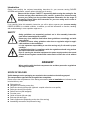
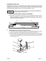
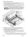
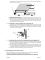
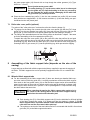
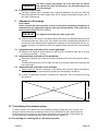
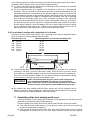
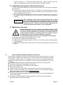
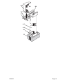
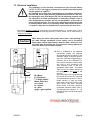
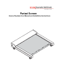
Parizzi Screen
Sunroof System User Manual and Installation Instructions.
Introduction
Please read carefully the enclosed assembling instruction for your sunroom awning PARIZZI
SCREEN and familiarize yourself upfront with this type of awning.
Please read the chapter "SAFETY" imperatively before using the awning for the
first time and pay close attention to this „caution“ symbol since it does not only
concern your safety but also provides important information for the usage of
this awning. Please follow this instruction for your own safety and in order to
avoid possible injuries!
If you carefully follow this assembly instruction you will be able to operate your sunroom awning
PARIZZI SCREEN in a reliable condition. In addition you will find information on function, handling
and troubleshooting in case a problem might occur.
SAFETY
Safety guidelines are respectively pointed out in this assembly instruction
each time a hazard might be possible!
Please pay close attention and follow these guidelines accordingly and with
extra caution!
In addition to these safety guidelines other laws or regulation might be applicable and have to be considered.
It is the operators responsibility to use this awning only if safe and in proper
condition.
A qualified electrician in compliance with the regulations should only perform
the required electrical connections.
Prior to opening the electrical equipment the power supply needs to be turned
off and secured against unauthorized restart and to ensure the unit is without
power.
DANGER!
When working with electrical components the accident prevention regulations
are subject to follow!
SCOPE OF DELIVER
Visible damages on the packaging are required to be recorded on the delivery papers!
The transportation agent will not recognize later complaints.
Please ensure the completeness of the awning accessories prior to installation as indicated on the
included delivery note:
Right guide rail
Left guide rail including motor drive
Roller tube housing back profile (Optional: coupled roller tube cover profile)
Roller tube housing front profile
Roller/Front bar (dual wrapped)
Front bar cover
Guide rail hoods (left and right)
End caps (left and right)
Fabric support tube (depending on the size of the awning)
Assembling accessories kit (enclosed in bag)
Installation of this unit
If this awning will be mounted on i.e. timber constructions or other structures which tend to “work” we
recommend to mount aluminum crossbars prior to the installation of the sunroom awning PARIZZI
SCREEN and install the awning on top of the crossbars (for example: the weight of the entire unit with
the dimensions (width x depth) 4.60 meter x 5.50 meter equals approx. 112 kg).
In order to ensure sufficient drainage the unit needs to be installed with a
minimum inclination of at least 10o!
Caution!
1
Assembling of the guide rail attachments/brackets
~ 300
8
160
125,5
8
98,5
Depending on the projection of the awning 2 to 4 guide rail attachments (8) per side rail are
included. The attachments need to be carefully aligned and positioned on the structure (for
example "D") followed by a firm tightening of the bolts but do not tight yet all the way (D1)
(please refer to the following drawing).
2
27
min. 200
max. 500
min. 140
max. 800
D
max. 6000
Assembling of the left guide rail (motor drive)
The next step is the mounting of the left guide rail onto the already fixed guide rail attachment (8). The right guide rail and both guide rail covers will follow at a later stage.
First the rail plate (8.2) can be shifted if necessary within the main plate (8.1). Afterwards
the left factory pre-mounted guide rail (10) has to be fastened with the help of the rail claws
(8.5) as shown in the drawing. At this time the M6-nuts (8.4) should not yet constantly tightened to their bolts (8.3).
10
D1
8.4
8.1
8.5
8.3
8.2
03/2003
Page 01
3
Assembling of the tubular motor
First the tubular motor needs to be installed onto the left guide rail (10). Remove the tape,
which was provided as a transportation lock from the tubular motor (14).
Now push the motor power cable (19) through the drill hole in the roller tube free end bushing with pin (16) and continue to push so it can slide smoothly into the back part of the cassette box (26) (please see also chapter 7 and 15).
Next push the square adaptor end (15) all the way until it stops into the motors (14) milling
groove of the roller tubes free end bushing (16) and pull the motor cable flat. Finally, the
locking mechanism needs to be tightened firmly with the M4-oval head screw (16.1).
The motor power connection cable has to be pulled completely
though the roller tubes free end bushing. It is critical that there is
no loop between the motor and the free end bushing and the
safety bushing needs to be placed as specified in chapter 7.
Caution!
26
20
1.1
26.1
17
16 15
28
28.1
16.1
14
27
1 1.1
2.1
2
5.3
3
18
4
29.1
29
5
6
7
T
6.2
20.1
6.1
7
8
19
5.3
5.1
13
29.1
29
5.2
9.1
11
8
10
4
9.2
9
21
23
11.1
22 8
Assembling of the roller tube and front winding profile onto the left guide rail
Now it is time to assemble the roller tube and the front winding profile as well as the fabricconcealing roller support (if available) (please see also chapter 8).
The fabric twin sleeve has been factory pre-assembled.
In order to mount the front profile (6) evenly to the guide rails, the front profile carrier (21)
has to be through rotating of the gear wheel (13) placed within a distance of approx. 245
mm to the wheel hub. In this position the groove (13.1) of the gear wheel has to point upwards (please see also the drawing in chapter 10.2).
Depending on the depth of the awning the front winding profile (6) needs to be pre-covered
with enough amount of fabric (T). The right amount of fabric can be found out with help of a
piece of supporting tape (K) for assembly purposes. During this assembly process the dis-
Page 02
03/2003
tance between the roller tubes need to be approx. 250 mm. After the assembly the supporting tape needs to be removed.
T
6
3
250mm
K
Roller tube (3) and front winding profile (6) as specified in chapter 4 need now to be connected to the left guide rail (10).
Thereto the roller tube (3) needs first to be pushed completely and all the way to the stop
with the guide rails already attached tubular motor (14) onto to the roller tubes bearing (16).
The fabric’s turnbuckle pin (22) now has to snap into the drill hole of the front profile carrier
(please see also the drawing in chapter 3).
5
Preparation for the assembling of the right guide rail
The gudgeon (23) of the assembling accessories kit needs to now to be placed into the right
front profile carrier (21) and in a position where the milled part of the gudgeon can be safely
secured with the clamping screw (25) and has to be tightened firmly. Now place the supplied
spacing tube (24) over the gudgeon.
25
1,5mm
23
24
6
21
Assembling of the roller tube and front winding profile onto the right guide rail
To ensure the same positioning of the roller tube and front winding profile on both guide
rails, prior to installation, the right guide rails gear wheel needs to be positioned analogical
to the left gear wheel (13) as specified in chapter 4.
Thereto the already assembled right guide rail (4) needs to be pushed completely onto the
roller tube (3) respectively front winding profile (6) so that the right roller tube bearing is fully
covered and the gudgeon (23) snaps entirely into to the drill hole of the front winding profile.
In this position install the right guide rail (please see also chapter 2).
7
Assembling of the roller tube housing
For the assembling of the roller tube housing the already up to this stage assembled awning
needs to moved away from the rear (house) wall for approx. 50 mm.
Place the rear cassette box profile (26) onto the guide rails and as shown in chapter 3, connect the profile with the two supplied M6 x 16 mm counter sunk bolts (26.1). Thereby pull
03/2003
Page 03
the motor power cable (19) flat and with no loop though the rubber grommet (18) (Type:
H05VV 4 x 1,5 mm2).
Caution!
Do not jam the motor power cable!
The safety bushing (17) on the motor cable has to be telescoped
into the guide rail (10) until the bushing is all the way covered by
the rear cassette box profile so that a damaging of the cable from
the gear wheel (13) can be prevented.
Place the front cassette box profile (1) into the rear cassette box profile (26) and screw
firmly with the two supplied M6 x 16 mm counter sunk bolts (1.1) Now the awning can positioned back to the rear (house) wall.
7.1 Roller tube cover profile (optional)
The option of the "roller tube cover” encloses the roller tube from the bottom (3).
To prepare for the fitting, first connect the roller tube cover profile (28) with the PVC hinge
profile (27) to the rear cassette box profile (26). Now push the two fixing poles (29) into the
groove (28.1) of the roller tube cover profile (please see also the drawing in chapter 3
The fitting of the assembled parts into the awning will be as described in chapter 7 the same
as for the assembling of the rear cassette box profile (26).
To attach the roller tube cover profile (28) to the guide rails raise the profile a bit and push
one fixing pole (29) at a time to the left and the other one to the right into the drill hole of the
positioning log (30). Next bend the dowel pins (29.1) down and secure each fixing pole by
screwing a M6 x 10 grub screw (30.1) into the positioning log, which prevents the slipping.
8
30.1
29
30
29.1
28.1
Assembling of the fabric support tube (depends on the size of the
awning)
Larger awnings are fitted with a fabric support tube (factory supplied) to prevent the sagging of
the fabric. The fabric support tube can be optionally equipped as either a fix or a wheeled feature.
8.1 Wheeled fabric support tube
For the assembling of the fabric support tube (5) there are already pre-installed fabric support tube carriers inside the guide rails. A coupling mechanism connects the fabric support
tube carrier to the front profile carrier (21) so that the fabric support carrier will automatically
extend to the center of the guide rail. Already at this point and as described in chapter 4 the
fabric support tube needs to be in position. A bit of prestidigitation is required when fitting
the three axles at the same time.
Caution!
When retracting the awning the fabric support tube needs to be in
the center of the awning! Never move the fabric support tube by
hand since the carriers will otherwise jam!
Push bearing pins (5.2) of the fabric support tube (5) into the individual in drill hole left/right
of the fabric support tube carrier (5.1) (please see also the drawing in chapter 3). Fit the
fabric support tube in a position that the visible sheet-metal screws point towards the
roller tube box and the short steel cables point up!
The eyelets on each end of the steel cable need to be connected with the M6 x 8 mm hexagon bolts (5.3) to the fabric support tube carrier.
Page 04
03/2003
Caution!
The fabric support tube always has to be fitted with the narrow
side up and never flat! The factory pre- set adjustment screws are
not to be changed!
8.2 Fixed fabric support tube
This fabric support tube is equipped with a standard attachment on each end. With this
standard attachment the fabric support tube will be clamped underneath the guide rails in
the center of the awning.
9
Alignment of the awning
Dear installer,
Please note that after the conclusion of the so far described assembling information it is
imperative that you adjust and verify the right-angle and parallelism of the guide rails of
the sun room awning PARIZZI SCREEN !
Caution!
The alignment must take place with a great care!
Align the awning with help of a measuring tape and the guide rail attachments/brackets that
the following terms are kept in mind. The concept of the guide rail attachments/brackets is to
relocate the entire awning forward, backward or sideways so that all distances can be corrected if necessary. Only when the awning is aligned properly the side rails can be tightened
firmly.
9.1 Adjustment and verification of the correct right angle
Measure both diagonal measurements (D) with help of a measuring tape and verify their
conformity (tolerance: ± 5 mm)!
9.2 Adjustment and verification of the parallelism
Measure the distance (P) at least on the three different places of the awning with a measuring tape.
This distance always has to be the same and has to be equal the depth of the awning at the
time of the order!
9.3 Adjustment and verification of the axial play
Please make sure that the "Axial play" of the spacing tubes (24) are kept at least approx.
1,5 mm apart along the entire sequence (please see also drawing in chapter 5)!
In case a re-adjustment becomes necessary, the "Axial play" can be corrected by moving
the guide rail.
D
P
10 Pre-winding of the tension spring
To ensure tension of the fabric cover once extended a tension spring has to be mounted. This
spring is located inside the front winding profile (6) and is attached to a fabric tension adjuster,
which requires a pre-winding. For this purpose described moving directions of the awning can
be achieved with a programmable tester cable (please see also chapter 15).
10.1 Pre-winding of an awning with a 4, 00 meter projection
03/2003
Page 05
Up to 4-meter projection a constant stretching of the fabric tension adjuster takes place, which
guarantees that the awning cover will be taut at its largest extension.
To pre-wind the fabric tension adjuster the front winding profile (6) needs to be extended
about 30 cm from the roller tube housing.
The two long M6-screws (6.2) supplied in the accessory kit serve as a pre-stretching
assistance. They are needed for pre-stretching and have to be placed alternately into the
accessible drill holes (6.1) of the fabric tension adjuster gudgeon in order to turn the tension
spring towards the direction of the awnings extension and thereby stretch the tension spring
(please see also drawing in chapter 3). Simultaneously the awning cover will be stretched
tautly onto the front winding profile (6). In order to maintain the setting of the adjustment
spring, now set the stretching screw (23) in the front winding profile carrier (21) by using a 5
mm allen wrench and screw it against the straight positioned clamp surface of the fabric
tension adjuster gudgeon. Since the gudgeon has four of these clamp surfaces the spring
can be stretched in each case for 90 o . Please do only stretch the spring until the cover is
tight since the tension will automatically increase once the awning extends.
10.2 Pre-winding of awnings with a projection of 4 to 6 meter.
Projections of more than 4 meter require a pre- stretching of the spring at designated place,
which is subject to the awning depth (please see table).
Projection (a) in cm
Stretching distance (l) of the front winding profile
400 ... 430 cm
430 ... 460 cm
460 ... 500 cm
500 ... 540 cm
540 ... 570 cm
570 ... 600 cm
60 cm
100 cm
130 cm
170 cm
200 cm
240 cm
a
l
13.1
13
~ 245mm
21
6
To pre-wind the fabric tension adjuster the front winding profile (6) needs to be moved out
according to the table (I) from the roller tube housing. Since the cover will now be at this
point subject to considerable sagging it has to be first rolled back onto the front winding profile (6) and next as described in chapter 10.1 pre-winded. Please do only stretch the spring
until the seams on the edges of the cover are relatively taut.
Please note that the fabric dip in the center of the awning can be
never completely eliminated! Therefore do not overstretch the
fabric cover since it could cause unnecessary stress to the tubular
motor (in extreme cases above the permissible maximum torque).
Caution!
By extending the front winding profile the fabric tension will now be increased until its
maximum projection. When retracting the awning the same fabric tension will be provided
until the awning is fully retracted inside the roller tube housing.
11 Assembling of the front winding profile cover
To protect the fabric (T) from soiling and to maintain a clean appearance of the awning a cover
profile will be installed to the front winding profile (6).
The two supplied cover profiles and the four counter sunk bolts M6 x 25 mm are needed.
First push the cover profile bracket (11) into the slot in each end of the cover profile (9)
(please see also drawing in chapter 3).
The mounting of the cover profile on the front of the front winding profile carrier (21) will be
accomplished by screwing on the two cover profile brackets (11) with the four supplied
Page 06
03/2003
counter sunk bolts (11.1). Please note that the water drip edge (9.2) needs to point upwards. For this application an Allen wrench SW 4 with round head is needed.
12 Assembling of the guide rail hoods and end caps
To close an open gap between the guide rails and the fabric, clip on the guide rail hoods on
both guide rails.
To attach both supplied guide rail hoods (7) a few taps with a rubber hammer are recommended (please underlay a piece of wood for protection) to clip on the guide rail hoods to
the top of the guide rails (4 and 10).
To mount the roller tube housing end caps (2 and 20) to the roller tube housing, use each of
the supplied counter sunk bolts M6 x 16 mm (2.1 and 20.1) (please see also drawing in
chapter 3).
Caution!
After completion of the sunroom awning, please assure to install
the round rubber-sealing strip between the roller tube housing
front profile and the roller tube housing back profile to protect the
awning from water. Failing to install the rubber-sealing strip can
result in permarment water stains on the awning fabric.
13 Maintenance and repair
During maintenance and repair work to the sunroom awning PARIZZI
SCREEN the awning may not be operated! Disconnect the power supply
and secure against unauthorized re-connection. On awnings without an
electrical power separation an existing wind sensor must be “blocked”
by lashing and the controls needs be switched to „manually”.
The following maintenance work is to be accomplished once annually:
Cleaning of the guide rails from possible dirt (i.e. leaves).
Lubrication of the guide rails with Silicon spray.
Light greasing of the spring connector on the back of the fabric support tube with graphite
consisting grease.
Cleaning of the water spouts on the bottom side of the guide rails and the roller tube cover
profile.
14
Spacer bracket installation (optional accessories)
In cases where it might be necessary to elevate the awning from the roof structure (i.e. vents)
standard spacer brackets can be mounted to the rafters. These pre-mounted spacer brackets
are available in different length. The installation of an awning is only possible with spacer
brackets of the same length. For the installation on rafters the spacer brackets need to be disassembled.
For disassembling of the spacer brackets first remove the bolts (8.3) from guide claws.
Remove the rail claws (8.5) including the rail plate (8.2).
Now remove the flat M10 nut (8.6) with the u-washer (SW 17).
Remove top rail guide (8.9).
Lift spacer tube (8.7) including M10- tension screw (8.8) out of the bottom main plate (8.1)
Screw on bottom main plate (8.1) as described in chapter 2 to the rafter (D). Important
hereby is the usage of solid and suitable countersunk screw!
Now spacer brackets must be re-assembled in reverse order.
Therefore all pieces must be aligned with help of the flat M10 nut (8.6) and tightened with
the use of the u-washer.
As already described in chapter 2, align the guide rails (10 and 4) on top main plate and
clamp down with help of the rail claws (8.5)
03/2003
Page 07
4/10
8.9
8.6
8.5
8.3
8.2
8.7
8.8
8.1
D
03/2003
Page 09
15 Electrical installation
The installation of the electrical connections for the sunroom awning
PARIZZI SCREEN can only be performed by a certified electrician (please
see the chapter on „SAFETY“.
By installing the awning drive (motorization) an all contacts disconnection from the power supply must be provided within at least a 3 mm contact opening per pole according to VDE 700. All switching elements used
are required to be either mechanically or electrically lockable, have to
have designated zero position and are not permitted to receive their Nsupply through the drive. The exits of the switching elements have to be
in neutral position when not in operating mode. Other electrical devices
i.e. lamps or relays are not permitted to be connected to the same drive.
Drives with electronic switch off devices can be connected parallel (i.e. coupled units). Therefore the maximum rated load of all controlling devices (i.e. timer, switch, sun or wind control) is
subject to be minded.
Caution!
M
M
gn/ge
bl
br
E
sw
When wiring the motor cable please assure that a later jamming of
the cable through movements of the awning can be prevented!
Sharp edges, which might interfere with the cable, need to be covered with tape. Ensure that the connections are facing upwards towards the motor to avoid water seepage.
E
230V
PE
N
L1
T
03/2003
M = Motor
E = Electronic
T = Single switch
Motor cable (4 x):
sw = black
br = brown
bl = blue
gn/ge = green/yellow
Prior to installation of the electrical
connections (please see opposite
wiring diagram) the pre-setting of the
electronic switch off devices according to the enclosed programming instructions has to be completed. For
this purpose connect the motor cable
with help of wire connectors and
color matching order to the programmable tester cable. This tester
cable can only be used for the time of
the testing period and never for the
end use!
After completion of the programming
the awning should be fully extended
and retracted several times to ensure
proper function. In case the motor
shuts down, the motors build in shut
down device has been activated
which means its thermal protection
guarantees maximum safety. After a
cool down period of approx. 15 – 20
minutes the motor will be ready again
to start up.
Page 09