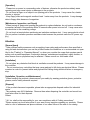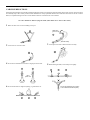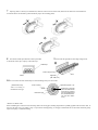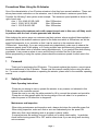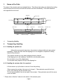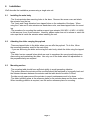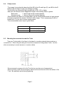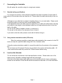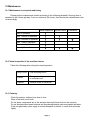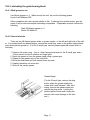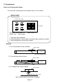
1
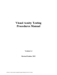
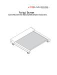
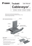
IS·ISP Actuator
Operating Manual
Intelligent Actuator, Inc
This publication was written to assist you in better understanding this part of your IA system. If you require further assistance, please
contact IA Technical Support. For Central and East Coast Time Zones, please call our Itasca, IL office at 1-800-944-0333 or FAX
630-467-9912. For Mountain and Pacific Time Zones, please call our Torrance, CA office at 1-800-736-1712 or FAX 310-891-0815;
Monday thru Friday from 8:30AM to 5:00PM.
Intelligent Actuator, Inc.
U.S. Headquarters
2690 W. 237th St
Torrance, CA 90505
310-891-6015 / 310-891-0815 FAX
Central Region Office
1261 Hamilton Parkway
Itasca, IL 60143
630-467-9900/ 630-467-9912 FAX
Eastern Region Office
7 S. Main St. Suite F
Marlboro, NJ 07746
732-683-9101 / 732-682-9103 FAX
www.intelligentactuator.com
Publication No: IAI-076
© Aug 2002 Intelligent Actuator, Inc. All rights reserved.
No portion of this publication may be reproduced, stored in a retrieval system, or transmitted, in any form or by any means, electronic,
mechanical, recording, or otherwise, without the prior written permission of Intelligent Actuator, Inc.
Disclaimer
The information and technical data contained herein are subject to change without notice. Intelligent Actuator, Inc. assumes no
responsibility for any errors or omissions regarding the accuracy of the information contained in this publication.
Safety Precautions
Please read the "Safety Precautions" section carefully before selecting a model or operating
the products for proper operation.
Please follow the following safety precautions to operate the products properly and prevent any
injury to you or others or loss of properties from occurring.
Warning signs are categorized as "danger," "warning," "caution," and "attention" based on the
degree of danger and impediment.
Danger
The contents are assumed to cause danger leading to death or severe injuries if operated improperly.
Warning
The contents are assumed to have the possibility to cause death or severe injuries if
operated improperly.
Caution The contents are assumed to have the possibility to cause injuries or material damage.
Attention
The contents do not have the possibility to cause injuries, but should be followed to operate the X-SEL controller properly.
The products designed and manufactured as a general industrial machine part.
The person with sufficient knowledge and experience such as a system designer or the person in charge of this machine, must read the "Catalog" and "Operating Manual" (especially the
"Safety Precautions" sections in both materials) before selecting and operating this machine. It may
cause danger if operated improperly.
Please read the operating manuals for all machines such as an actuator and a controller.
It is your responsibility to verify and determine the compatibility of the products with your system.
After reading the "Catalog" and "Operating Manual," please make them easily accessible to operators.
When you give or rent the products to others, the "Catalog" and "Operating Manual" must be
attached to a visible area of the body of the products for the new user to learn safe and proper operations.
Danger, warning, and caution items in the "Safety Precautions" section are not exclusive.
Please refer to the "Catalog" and "Operating Manual" of each individual machine for their safe and
proper operations.
Danger
[General Items]
Please do not use the products for the following uses.
1. Medical equipment to support and maintain human life and health.
2. Mechanism or mechanical device to move or transport people
3. Important maintenance parts of mechanical devices
The X-SEL controller was not intended or designed for the usage that requires high degree of safety.
We are not responsible for loss of life. The warranty pertains to the purchased product only.
[Installation]
·Avoid using the products near combustible, flammable, or explosive objects. It may combust, ignite,
or explode.
·Avoid using the products near the place where it might be splashed by water or oil.
·Do not cut and re-connect cables to extend or reduce the length of cables for the products.
Alteration cause fire.
[Operation]
· A person who has a pace maker must keep at least 1 meter of distance from the products.
Powerful magnetism of the products may cause improper operation of pace makers.
· Do not splash water over the products. If the products gets wet, washed, or used under water,
abnormal operation may occur and cause injuries, electric shocks, or fire.
[Maintenance, Inspection, and Repair]
· Do not rebuild the products. Abnormal operation may occur and cause injuries, electric shocks,
and fire.
· Do not improperly disassemble and reassemble the products in any way that may affect the basic
structure or performance and function of the products. It may cause injuries, electric shocks, and
fire.
Warning
[General Items]
· Any specifications not specifically addressed in this operating manual should not be attempted.
These specifications may cause malfunction, termination of operation, or damages. They may significantly shorten the life of the products. Please avoid exceeding the specified maximum payload
and maximum speed.
[Installation]
· Design a safety circuit or device to prevent material damages or physical injuries when the
machine stops operating during an emergency stop or power failure.
· An actuator and a controller must be grounded by a D-type grounding construction (the former third
type grounding construction; grounding resistance under 100Ω). A short circuit may cause electric
shock or improper operation.
· Before supplying electricity to or operating the products, always confirm safety of a surrounding
area. If electricity is supplied to the products without confirming safety of a surrounding area, it may
cause electric shocks or injuries by contacting operating parts.
· Avoid improper wiring by confirming proper wiring of the products with the "Operating Manual." A
cable and a connector must be connected tightly. If not tightly connected, they may cause abnormal
operation or fire.
[Operation]
· Do not touch a terminal base or any switch when power is on. It may cause electric shock or
abnormal operation.
· Confirm the servo is off (by using a teaching pendant) when you manually move the slider of the
actuator (manual position adjustment, etc.) It may cause injuries.
· Although cables for the products are very flexible, they are not robot cables. Do not place cables
in a movable wiring duct (such as a cable track) with a radius smaller than the specified size.
· Do not damage the cables. If cables are damaged, forcefully bent, pulled, wound, placed under a
heavy object, or pushed in, they may cause fire, electric shocks, or abnormal operations due to
short circuits or voltage/current overload.
· Please turn off power when power failure occurs. If power is not turned off, the products may suddenly resume its operation after electricity is restored and it may cause damages to the products.
· If the products generates abnormal heat, smoke, or smell, turn off power immediately. If you continue using the products, damages or fire to the products may occur.
·If a protection device (alarm) of the products goes off, disconnect power immediately. Abnormal
operation of the products may cause injuries, break down of or damages to the products. After turn-
ing off power, investigate the cause of the alarm, eliminate the cause, and turn on the power supply.
· Turn off power immediately if the LED of the products is not lit after turning on the power. A protection device (such as a fuse) may have blown out. Please request a repair to our local sales office.
[Maintenance, Inspection, and Repair]
· The power supply must be completely off before maintenance inspection, adjustment, or replacement work begins on the products. Follow the instructions below during maintenance work.
· During inspection, post a sign such as, "The machine is being inspected. Do not turn on power.,"
in a visible place to prevent a third person from carelessly turning on power.
· When more than one person is doing a maintenance inspection, always confirm everyone's safety
by vocally warning turning on and off the power switch.
[Disposal]
· Do not dispose the products in fire. The products may explode or generate toxic gas.
Caution
[Installation]
·Do not expose the products to direct sunlight (ultraviolet rays), or place it near dust, salt, iron powder, humid environment, or in the atmosphere that contains organic solvent, phosphate ester working oil, sulfurous acid gas, chlorine gas, or acids.
It may cause the products to lose its functionality in a shorter time or cause rapid deterioration of its
performance or shorten the life of the products.
·Do not use in an environment subject to contamination by corrosive gases (sulfuric acid or
hydrochloric acid), combustible gases, or inflammable liquids. It may cause strong deterioration due
to corrosion, combustion, or explosion.
·When you use the products in the following areas, please take sufficient isolation measures. If not
isolated, it may cause improper operation.
1. The area where strong electric current or a high magnetic field exist
2. The area where electric discharge occurs such as a welding work location
3. The area where electric noise due to static electricity is generated
4. The area where it may be exposed to radioactivity
· The controller should be placed in an area least exposed to trash and dust. If they are placed in
the area exposed to a large quantity of trash and dust, they may operate improperly.
· Do not place the products in an area where excessive vibration or shock (4.9m/S2 or more) occurs.
Excessive vibration or shock may cause improper operation.
· Place an emergency stop device in the area where suspension can be commanded immediately in
case of danger.
· Secure an extra space for maintenance when mounting the products. Failure to secure sufficient
space disables daily inspection or maintenance and causes suspension of the device or damages to
the products.
· When mounting the products, do not hold moving parts of the products or cables. It may cause
injuries.
· Use only IA cables when connecting actuators and controllers. Use a combination of IA products
for component parts such as actuators, controllers, and teaching pendants.
· Before mounting or performing adjustment on the products, please post a sign such as "The
machine is being adjusted. Do not turn on power." to prevent anyone from carelessly turning on the
power. If the power is turned on carelessly, the actuator suddenly starts operating and may cause
electric shock or injuries.
[Operation]
· Please turn on power in commanding order of devices; otherwise the products suddenly starts
operating and may cause injuries or damages to the products.
· Do not insert a finger or an object in an opening part of the products. It may cause fire, electric
shocks, or injuries.
· Keep floppy disks and magnetic media at least 1 meter away from the products. It may damage
data in floppy disks because of magnetism.
[Maintenance, Inspection, and Repair]
· When turning off power and opening the products to replace batteries, do not touch a condenser
connection terminal of the products within 30 seconds after power is turned off. It may cause electric shock due to the remaining voltage.
· Do not touch a terminal when performing an insulation resistance test. It may cause electric shock.
(Do not perform insulation pressure resistance tests because the products uses the DC power supply.)
Attention
[General Items]
· Take sufficient safety measures such as applying lower rating and performance than specified or
using fail-safe devices when you use the products under the conditions or in environments not specified in the "Catalog" or "Operating Manual", or when you consider the usage that requires special
safety such as aerial equipment, combustion devices, entertainment equipment, safety devices, or
when human lives or properties may be affected. Please consult our local sales office.
[Installation]
· Do not place any obstacles that block air ventilation around the products. It may cause damage to
the controller.
· Do not construct any controllers that may cause payload to fall during an electrical failure. Please
construct a control to prevent tables and payload from falling during electrical failure or emergency
stop.
[Installation, Operation, and Maintenance]
· When handling the products, please secure your safety by wearing protective gloves, protective
glasses, and/or safety shoes as required.
[Disposal]
· If the products becomes inoperable, please take an appropriate disposal method for industrial
waste.
·The products uses Ni-Cd batteries. Remove them when disposing the controller and consult our
local sales office for their disposal.
Others
* IAI, Inc. shall not be responsible for your non-compliance with all "safety precautions."
*Please contact our local sales office in your area for any inquiries regarding our products. Please
refer to a list of addresses and phone numbers of our sales offices in the end of our catalog.
CABLING PRECAUTIONS
When using the IS actuator and controller to build an application system, it is important to position and lay out the cable correctly. If this is not done,
the cable may snap or have a faulty connection that could lead to a variety of problems which in turn could cause the actuator to run out of control.
Below, we explain the things not to do to ensure that the cables are connected in the correct fashion.
Ten “Do’s and Don’ts” When Laying Out Cable (Please make sure to observe these rules!)
1
Make sure there is no excessive bending at one spot.
Steel band
(piano wire)
Bundle loosely
2
Do not twist or crease the cable.
4
Do not have rotational force exerted at a single spot on the cable.
3
Do not place the cable so that it stretches too tautly.
5
When affixing the cable, do not clamp it too tightly.
Use a
spiral cord
6
Do not let the cable be caught in anything, or get dented or cut.
Do not use spiral tubing on a section
of the cable that bends frequently.
7
If placing cable in a cableveyor or flexible tube, make sure it does not twist around. Also, make sure the cables have some freedom of
movement and are not bunched up (cable should not project out at bending points).
8
9
The amount of cable placed inside a cableveyor should
be about 60% of the space capacity of the cableveyor.
Do not mix the signal line in with a high voltage circuit.
Cableveyor
Power supply circuit
Duct
Cable
10
Signal line
(flat cable, etc.)
In a case where the cable will be subject to forced bending, always use robot cable.
[Standard structure]
Varies according to
manufacturer and type
Signal line (copper + tin)
Outer covering
Shield
Protective layer
Absorption material
(when the cable bends
and there is pressure
from the outside signal
line, this absorbs the inner and outer difference)
*When to use Robot Cable
When assembling two or three axes and connecting cable to the moving parts, bending weight will be repeatedly applied to the base of the cable. In
this case, the cable core is very likely to snap. To prevent this from happening, we strongly recommend the use of robot cable which has greatly
improved capacity to withstand bending.
Table of Contents
1. Foreword · · · · · · · · · · · · · · · · · · · · · · · · · · · · · · · · · · · · · · · · · · · · · · · · · · · · · · · · · · · · · · · · · · · · ·1
2. Safety Precautions · · · · · · · · · · · · · · · · · · · · · · · · · · · · · · · · · · · · · · · · · · · · · · · · · · · · · · · · · · · · ·1
3. Names of the Parts · · · · · · · · · · · · · · · · · · · · · · · · · · · · · · · · · · · · · · · · · · · · · · · · · · · · · · · · · · · · ·2
4. Transporting, Handling · · · · · · · · · · · · · · · · · · · · · · · · · · · · · · · · · · · · · · · · · · · · · · · · · · · · · · · · · ·3
5. Operating and Storage Environment · · · · · · · · · · · · · · · · · · · · · · · · · · · · · · · · · · · · · · · · · · · · · · · ·5
6. Installation · · · · · · · · · · · · · · · · · · · · · · · · · · · · · · · · · · · · · · · · · · · · · · · · · · · · · · · · · · · · · · · · · · · ·6
7. Connecting the Controller · · · · · · · · · · · · · · · · · · · · · · · · · · · · · · · · · · · · · · · · · · · · · · · · · · · · · · · ·8
8. Load on the Actuator · · · · · · · · · · · · · · · · · · · · · · · · · · · · · · · · · · · · · · · · · · · · · · · · · · · · · · · · · · · ·9
9. Setting Home Position · · · · · · · · · · · · · · · · · · · · · · · · · · · · · · · · · · · · · · · · · · · · · · · · · · · · · · · · · ·10
10. Maintenance · · · · · · · · · · · · · · · · · · · · · · · · · · · · · · · · · · · · · · · · · · · · · · · · · · · · · · · · · · · · · · · ·12
11. Warranty · · · · · · · · · · · · · · · · · · · · · · · · · · · · · · · · · · · · · · · · · · · · · · · · · · · · · · · · · · · · · · · · · · ·16
12. *Supplement- How to use homing mark sticker · · · · · · · · · · · · · · · · · · · · · · · · · · · · · · · · · · · · ·17
Precautions When Using the IS Actuator
One of the characteristics of our IS series actuators is that they have several variations. These variations place certain restrictions on the actuators, one of which relates to maximum speed limits.
Consider the following 3-axis system as an example. The maximum speed possible is shown to the
right of each axis.
Axis 1: IS-L-X-MX-20-200-1400
Max 1000mm/sec
Axis 2: IS-M-Y-M-10-100-600
Max 500mm/sec
Axis 3: IS-S-Z-M-4-60-300
Max 200mm/sec
Failure to observe the maximum value with respect to each axis in this case, will likely result
in problems with the level of noise generated and vibration.
After studying the various ways our customers use their systems, where we should have applied a
parameter trap at the smallest maximum speed of the three axes which is 200mm/sec, we set the
speed limit parameter in our controller so that it can be used up to the maximum value of
1000mm/sec. Accordingly, if you are running each axis independently, make sure to observe the
maximum speeds given in the catalog, or if running multiple axes simultaneously, please program
the speed at the lowest value of all axes running simultaneously. If you overlook this when issuing
commands, it may cause an alarm to occur and will tend to shorten the life of the system.
Before programming or using the system, please check the maximum speeds for each axis in the
catalog.
1
Foreword
Thank you for purchasing the IS Actuator. This manual explains the structure, correct operation and maintenance of the IS actuator. Please read this manual carefully before using the actuator. For more complete information on operating the actuator, please refer to the controller operating
manual.
2
Safety Precautions
Basic Operating Instructions
·Please do not attempt to use or operate the actuator in any manner not indicated in this
manual or the controller manual.
·Please be sure to use only the cable provided by IAI to connect the actuator and controller.
·Please do not allow people within the moving range of the unit when it is in operation or
when the power is ON since this is dangerous.
Maintenance and Inspection
·When doing maintenance and inspection work, always shut down the controller power first.
·When doing inspection, make sure that no one can inadvertently turn the power ON.
·Make sure that a sign indicating work in progress is clearly visible.
·If several persons are working, be sure to watch out for each other's safety. In particular,
check before turning power ON or OFF and let others know if you are doing work involving
axis movement.
Page 1
3
Names of the Parts
The name of the actuator parts are indicated below. The left and right sides are indicated by looking
at the actuator from the motor end with the actuator set down horizontally. Front end means the
side opposite the motor end.
Right side
Screw cover
Front end
Motor end
Left side
Front cover
Slider
Base
Reference plane
4
Transporting, Handling
4
Transporting, Handling
Upper side
Motor housing
Lower side
Encoder cover
Cable
4-1-1 Handling the packed unit
Unless there are special instructions, the actuator is shipped with each axis packed
separately. Please take care that the shipping box is not dropped or subjected to strong
impact during transport.
·The operator should not carry heavy shipping boxes by himself.
·If the shipping box is left standing, it should be in a horizontal position.
·Do not climb on top of the shipping box.
·Do not place heavy objects on top of the shipping box.
4-1-2 Handling the actuator after it is unpacked
Lift the actuator up by the base to remove it from the packing.
·When carrying the actuator, take care not to bump it. Take particular care with the front
cover, motor housing and the encoder cover.
·Do not exert excessive force on any part of the actuator. Take particular care with the screw
cover and cable.
* Please refer to Section 3 above for the names of the actuator parts.
Page 2
4-2
Handle for pre-assemble unit
4-2-1. Shipping with assembled
After assembled actuators are designed and have been tested, they will be shipped on a
pallet with a cover. To avoid movement of sliders during shipping, actuators are supported. Also for
assembled unit actuators, tip is supported to avoid shaking.
·The packaging is not designed to protect against dropping and collision shock, therefore,
please pay extra attention when handling. Also the box cover is not very strong, do not place
heavy objects on it.
·When you hang it by ropes or lift by fork lift, support the base of the pallet.
·When you put it down, avoid shocking and bouncing.
*After un-packing, please follow the following.
4-2-1. Handling for pre-assembled with device
When you un-packed the pre-assembled unit, please handle as follows:
·Fix sliders to avoid moving during shipping.
·When the tip is over hanged, support it appropriately to avoid movement by external shock.
·If shipping without supporting the tip, don’t shock more than 0.3G.
·When you hang actuator with device, by rope, rope must not touch them.
For loading by rope, use appropriate cushioning and directly catch X axis base body
·For Y axis, support the tip by another rope and keep them horizontally. To avoid that, it is
recommended that hook the rope on female screw of M8 (small type is M6) which is
connected to Y axis base.
·Please be careful not to put load on bracket, cover, and connector box.
Also do not pinch and bend the cables.
Page 3
5
Operating and Storage Environment
5-1
Operating environment
The actuator should be set up in an environment which meets the following criteria:
·Avoid direct sunlight.
·Avoid radiant heat from strong heat sources such as a furnace.
·Ambient temperature should be 0 ~ 40º C.
·The humidity should be less than 85% and there should be no condensation.
·Avoid exposure to corrosive or combustible gases.
·The area should have very little dust and be suitable for normal assembly operations.
·Avoid exposure to oil mist or fluids using in cutting.
·The unit should not be subject to vibrations greater than 0.3G.
·Avoid extreme electromagnetic waves, ultraviolet rays and radiation.
In general, the environment should be one in which an operator can work without protective gear.
5-2
Storage environment
The storage environment should be similar to the operating environment. In addition, you
must take precautions against condensation if the unit is to be stored for a long period of time.
Unless there are special instructions, we do not include moisture absorption agents when shipping
the unit. If you are storing the unit where condensation might occur, then you must treat the entire
packing or treat the unit itself after it is unpacked to prevent condensation. The unit can withstand
up to 60ºC during a short storage interval but only up to 50ºC if the storage period is longer than
one month.
Page 4
6
Installation
We'll describe the installation process using a single axis unit.
6.1
Installing the main body
·The X-axis actuator has mounting holes in the base. Remove the screw cover and attach
the actuator from the top.
·The Y-axis and Z-axis actuators have tapped holes on the underside of the base. When
using the Y-axis and Z-axis actuators as stand-alone units, use these tapped holes for mount
ing.
·The procedure for mounting the medium support type actuator (M-X-MX, L-X-MX, L-X-UWX)
is the same as for an X-axis actuator. However, please make sure not to release or catch the
wire rope that is inside the actuator when installing the unit.
6.2
Attaching the slider carrying the payload
·There are tapped holes in the slider where you can affix the payload. To do this, follow
the mounting procedure used for the main body.
· If you are anchoring the slider and moving the main body, attach the slider using the tapped
holes.
·The slider has two reamed holes which are used to reproduce the correct positioning when
dismounting and reattaching the slider. Use only one of the holes when fine adjustments to
the perpendicularity are required.
6.3
Mounting surface
·The mounting table should have sufficient rigidity to avoid generating vibration.
·The surface where the actuator will be mounted should be machined or be equally level and
the flatness tolerance between the actuator and the table should be within 0.05mm.
·Provide enough space around the actuator to permit maintenance work to be done.
·The slider travelling plane is the reference plane for the actuator base and the lower surface.
When travelling precision is required, use this as the reference plane for mounting.
Page 5
6-4
Clamp screws
·The screws for mounting the base should be M6 for the IS small type (S), and M8 for the IS
medium (M) and large (L) types (use hexagon sockets).
·For the bolts, we recommend high strength bolts of ISO- 10.9 or higher.
·Make sure the bolt and screw engagement length is the following value or greater:
Steel screw
-> same length as the nominal diameter
Aluminum screw
-> twice as long as the nominal diameter
·When attaching the base to a mounting table, use the special washer made for high strength
bolts that comes with the actuator if the bolt is M8 or larger. This is unnecessary for M6 or
smaller bolts. Do not use a common spring washer.
·The recommended screw torque is given below.
6-5
Screw nominal diameter
Screw torque
M6
7N·M (0.7kgf·m)
M8
26N·m (2.6kgf·m)
Mounting the connector box and the T-slot
There are T-slots (width of slot 4mm) in the base for mounting external devices such as a
connector box. When using the wiring kit, mount the connector box using these T-slots. Use the
slots as necessary to mount sensors or to anchor cables.
·We recommend a square nut for the T-slot but you can also use a hexagonal nut.
·When mounting, check the bolt length to make sure the end does not touch the bottom of the
T-slot. Be especially careful during tightening.
Page 6
7
Connecting the Controller
We will explain the controller wiring for a single axis actuator.
7-1
Standard wiring specifications
For a single axis actuator, unless otherwise specified we attach a standard 3 meter cable (5
meter option) to the actuator when we ship the unit. Please attach the cable end directly to the controller.
·Although we use cable that is resistant to bending fatigue, it is not robot cable. Please avoid
housing the cable in a wire duct with a small bending radius.
·In an application where the cable cannot be anchored, try to place the cable where it will sag
only under its own weight or use dedicated cable hose for large radius wire duct to limit the
load on the cable.
·Do not cut the cable to lengthen, shorten, or reconnect it.
·Do not pull on the cable or use excessive force to bend it.
If you wish to alter the cable, please consult with IAI before doing so.
7-2
Using custom stand-alone cable (ICS series)
When the customer specifies a stand-alone cable attached to the connector for the ICS
series, we ship the specified cable along with 0.3m of actuator cable.
·Using the custom stand-alone cable kit, connect the cable from the actuator to the connector
box.
·Two air hoses and 10 external I/O wires are provided in the custom self-standing cable. All
come unconnected inside the junction box. Please connect before using.
8
Load on the Actuator
·Do not exceed the load shown in the load specification column. Please make note of the
slider moment, allowable overhang length and the load weight.
·The body of the base warps easily when you use the actuator with the Y-axis overhanging.
Please use the actuator so that the Ma and Mc moments are less than 1/2 of the rated value.
Page 7
9
Setting Home Position
9-1
Principle of the homing operation
IA performs homing in the following manner.
1. The moving direction is determined by the parameters set by the homing command.
2. The software senses the mechanical end in the homing operation.
3. The slider reverses direction when this end is reached and the place where the Z phase
signal is detected becomes the reference point.
4. The slider travels further by an offset amount defined by the parameters and this position
becomes home.
9-2
Fine control of home position
The number of motor revolutions from the time the slider hits the stopper to when the Z phase
signal is generated is adjusted when the unit is shipped. The standard value of the backing distance
when the slider hits the stopper, reverses and then stops at the home position is:
Actuator
Reverse distance
from mechanical stopper (mm)
All IS Axes
5
As long as the homing direction is the same, you can make fine adjustments to the home
position for each actuator by changing the parameters based on this value. Adjustments are made
as follows:
1. Initiate the homing operation and confirm home.
2. After homing, move to the desired new home position, check the difference and adjust the
parameters. (adjusting in the minus direction is not allowed).
3. If you allow for ample offset amount the movement range is that much more limited. If the
offset is greater than 1mm, you will have to reset the stroke soft limit.
9-3
Changing home direction
If the home direction is changed after the unit is delivered, the home direction parameter must
be changed, and Z-phase may need to be adjusted. Please contact IAI.
Page 8
10 Maintenance
10-1 Maintenance check points and timing
Please perform maintenance checks according to the following timetable. Running time is
assumed to be 8 hours per day. If use is continuous (24 hours), then shorten the maintenance interval accordingly.
Visual Inspection Internal Check
Lubrication
Start of operation
After 1 month of operation
After 6 months of operation
After 1 year of operation
Semiannually thereafter
Annually thereafter
10-2 Visual inspection of the machine exterior
Check the following when doing the visual inspection.
Body Loose
Lose mounting bolts?
Cables
Damage to cables, connection
to controller box?
General
Unusual noise or vibrations?
10-3 Cleaning
·Clean the exterior surfaces from time to time.
·Wipe off dirt with a soft cloth.
·Do not spray compressed air on the actuator that might force dust into the crevices.
·Do not use petroleum-based solvents as they damage plastic parts and painted surfaces.
·If the unit gets badly soiled, apply a neutral detergent or alcohol to a soft cloth and wipe
lightly.
Page 9
10-4 Internal inspection
Turn the power OFF, remove the screw cover and do a visual check of the inside. Check to
see if there is any dust or foreign objects inside the unit and the condition of the lubrication. Even if
the grease is a brown color, the lubrication is fine as long as the travelling surface appears to be
shiny.
·The small type screw cover can be removed with a 1.5mm hexagonal wrench. The medium
and large type screw covers can be removed with a 2mm hexagonal wrench.
·Do not remove the front cover since it supports the ball screw.
·Do not remove the encoder cover since there are precision instruments inside.
!! WARNING !!
The encoder is built into the inside of the encoder cover. The encoder not only
detects the rotation angle and the home signal but also performs the critical
function of AC servo power line phase commutation and these phases are
adjusted precisely. Do not touch the encoder in any way to change home.
If the grease becomes dirty and dull or if the grease has worn away due to extended operating time,
lubricate the parts after cleaning them. After you finish inspection, tighten the mounting screws for
the screw cover. The screw torque should be for a cross-recessed head machine screw.
10-5 Cleaning the inside
·Use a soft cloth to wipe off dirt on the inside.
·Do not spray strong pressurized air that might force dust into the crevices.
·Do not use petroleum-based solvents, neutral detergents or alcohol.
Page 10
10-6 Lubricating the guide bearing block
10-6-1 What grease to use
Use lithium grease no. 2. When we ship the unit, we use the following grease.
Kyodo Yushi Maltemp SRL
Other companies also sell a grease similar to this. If ordering from another maker, give the
name of this product and request something comparable. Comparable products include the
following:
Shell Oil Albania grease no. 2
Mobile Oil Mobilux 2
10-6-2 How to lubricate
There are two M6 tapped grease holes or grease nipples on the left and right side of the slider. For actuators with no grease nipples, remove the screw plug, screw in the grease nipple attachment and squirt the grease in. (For the IS small type, use the grease nipple that comes with it to
lubricate).
1. Remove the screw cover. (Use a 1.5mm hexagonal wrench for the IS small type, and a
2.0mm wrench for the IS medium and large types.
2. Squirt the grease in from the grease nipple using a grease gun.
3. Repeat for the grease hole on the other side.
4. Move the slider back and forth several times by hand.
5. Repeat lubrication one more time.
6. Wipe off the excess grease.
Grease Nipple
(For the IS small type, remove the plug
screw, attach the grease nipple that
comes with it and lubricate. After lubricating, remove the grease nipple and
replace the plug screw. Leaving the
grease nipple in place and running the
actuator can cause damage to the actuator.)
Page 11
10-7 Lubricating the ball screw
10-7-1 Ball screw grease
When we ship the units, we use the following grease which is specifically for ball screws.
Kyodo Yushi Mal temp SRL
This product is well suited for ball screws and has excellent properties such as low heat generation. For comparable products , please refer to guide grease
!! WARNING !!
Never use any fluorine based grease. When mixed with a lithium based
grease, not only does the grease lose its performance but it can actually dam
age the actuator.
10-7-2 Lubrication
Clean the screw, then apply grease with your finger and spread it out by moving the slider
back and forth. After this, wipe off any excess grease leaking from the nut. Application is done this
way because if too much grease is applied, the agitation resistance increases and the ball screw
generates heat more easily. Also, when the ball screw rotates, excess grease is splattered on the
surrounding areas.
Page 12
11
11-1
Warranty
Warranty period
The warranty period is one year after IAI America ships the unit.
11-2
Scope of warranty
If a breakdown occurs within the period specified above and is due to the manufacturer's
error, we will repair the unit at no cost. However, the following items are not covered by this warranty.
· Faded paint or other changes that occur naturally over time.
· Consumable components that wear out with use.
· Unit seems to be noisy or similar impressions that do not affect machinery performance.
· Damage resulting from improper handling by the user or lack of proper maintenance.
· Any alterations made by other than IAI or its representatives.
· Breakdowns caused by using controllers made by other manufacturers.
· Any damages caused by fire and other natural disasters or accidents.
The warranty pertains to the purchased product itself and does not cover any damages that might
arise from a breakdown of the supplied product. Any repairs will be done at our factory. Even if the
product is still covered under the warranty period, we will assess a separate charge for sending
technicians to the customer's site.
Page 13
12. Supplement
How to use homing mark sticker
*Use this mark as homing direction indicator and so on as needed.
Sticker detail
Homing mark sticker
X 1 sheet
Graduation mark sticker X 4
(by the 1mm 10mm width)
Mark sticker X 4
1. The back side is adhesive.
2. Clean dirt and oil on the surface of actuators before putting on stickers.
3. Avoid putting them on the caution sticker.
Example
1. For homing direction mark as shown
Stick on slider
motor
Stick on homing side of base
2. For positioning mark as shown
Stick on slider
motor
Stick on designated positions
3. For displacement check as shown
Stick on slider
Stick on base
*Use 2 stickers when the actuator is stopped.
Page 14
Intelligent Actuator, Inc.
2690 W.237th St
Torrance, CA 90505
(310)891-6015 / (310)891-0815 (Fax)
Publication No.: IAI-076
Publication Date: August 2002