1
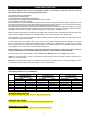
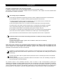
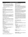
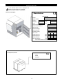
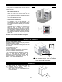
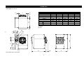
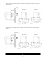
Gas fired room sealed unit heaters TECHNICAL INFORMATION, ASSEMBLY INSTRUCTIONS, USE AND MAINTENANCE RS/UHA RS/UHA-2 RS/UHA-4 BENSON HEATING LUDLOW ROAD KNIGHTON POWYS, LD71LP U.K. August 2003 Benson Heating is a Division of Benson Climate Systems Ltd COMPLIANCE NOTICES The Benson RS/UHA range has been independently tested and assessed, and has been found to meet the Essential Requirement of the following European Directives: Gas appliance Directive (90/396/EEC) Machinery Directive (89/392/EEC) Low Voltage Directive (73/23/EEC and 93/68/EEC) Electromagnetic Compatibility Directive (98/336/EEC and 91/31/EEC) Product Liability Directive (65/374/EEC) The manufacturer has taken reasonable and practical steps to ensure that Benson RS/UHA Range of Heaters are safe and without risk when properly used. These heaters should therefore only be used in the manner and purpose for which they were intended, and in accordance with the recommendations detailed herewith. The heaters have been designed, manufactured, assembled, inspected, and tested, with safety and quality in mind, there are certain basic precautions which the installer and user should be aware of, and they are strongly advised to read the appropriate sections of the information pack accompanying the heater, prior to installation or use. Benson Heating supports all new products being supplied to their customers with a comprehensive information pack; this clearly defines mandatory instructions for the safe installation, use, and maintenance, of the appliance(s). Where proprietary items are incorporated into Benson Heating products, detailed information and instructions are also provided as part of the information pack. It is the responsibility of the installer, owner, user, or hirer, of such products supplied by Benson Heating, to ensure that they are familiar with the appropriate information/manuals, supplied by the manufacturer, and that they are suitably aware of the purpose of the manuals and the safety instructions. In addition, operators must be suitably trained in the use of the appliance so as to ensure its continued safe and efficient use. Benson Heating has a commitment to continuous improvement, and therefore reserves the right to amend or change the specification of the RS/UHA Heater range subject to agreement from The Notified Body. Contained within the text of the manual, the words 'Caution' and 'Warning' are used to highlight certain points. Caution is used when failure to follow or implement the instruction(s) can lead to premature failure or damage to the heater or its component parts. Warning is used when failure to heed or implement the instruction(s) can lead to not only component damage, but also to a hazardous situation being created where there is a risk of personal injury. PIN NUMBER Notified Body PIN Reference is 0694BN3750 Type 1 2 3 4 5 6 7 RS/UHA Single Stage Burner Single Speed Fan Single Stage Code RS/UHA 50 3NAGBER016 RS/UHA 80 3NAGBER026 RS/UHA 105 3NAGBER036 RS/UHA 140 3NAGBER046 RS/UHA 200 3NAGBER066 RS/UHA 260 3NAGBER086 RS/UHA 325 3NAGBER106 RS/UHA-2 Two Stage Burner Single Speed Fan Two Stage Code RS/UHA 50-2 3NAGB2C016 RS/UHA 80-2 3NAGB2C026 RS/UHA 105-2 3NAGB2C036 RS/UHA 140-2 3NAGB2C046 RS/UHA 200-2 3NAGB2C066 RS/UHA 260-2 3NAGB2C086 RS/UHA 325-2 3NAGB2C106 VERSION SINGLE STAGE This heater has a single stage gas valve and a single speed axial fan . VERSION TWO STAGE This heater has a two stage Hi / Lo gas valve and a single speed axial fan. VERSION DUAL POWER This heater has a two stage Hi / Lo gas valve and a two speed axial fan . 2 RS/UHA-4 Two Stage Burner Two Speed Fan Dual Power Code RS/UHA 50-4 3NAGB21016 RS/UHA 80-4 3NAGB21026 RS/UHA 105-4 3NAGB21036 RS/UHA 140-4 3NAGB21046 RS/UHA 200-4 3NAGB21066 RS/UHA 260-4 3NAGB21086 RS/UHA 325-4 3NAGB21106 GUARANTEE The heater is supplied with a 2 year warranty on all parts. In addition to this there is also a 10 year time related warranty on the combustion chamber. The warranty commences from the date of despatch from the manufacturer, and is subject to the terms detailed within the manufacturer 'conditions of business'. The warranty may be invalidated if: a) The warranty registration/commissioning card has not been completed and returned to the manufacturer b) The installation is not in accordance with the general requirements of this manual c) The flue arrangement and air supply for the heater are not in accordance with the manufacturers recommendations, codes of practice, or similar standards d) Air flow through the heater is not in accordance with the manufacturers technical specifications e) Internal wiring on the heater has been tampered with or unauthorised service/repairs undertaken f) The main electrical supply input to the heater has been interrupted during the heating mode g) The heater has been subject to and affected by the ingress of water in any form h) The heater is not operated at the rating(s) laid down in the manufacturers technical specifications i) The heater has not been operated or used within the normal scope of its intended application j) The manufacturer's recommended minimum service requirements have not been complied with All warranty claims must contain the following information to enable processing to take place; (1) Heater model (2) Heater serial number (3) Order reference/date of order, together with full installation details (name and address) (4) Details or symptoms of fault (5) Installers name and address. Faulty parts must be returned to the manufacturer Spares Department, the address of which is provided on the rear cover of this manual. Any such parts will undergo inspection to verify the claim. Replacement parts supplied prior to this may be charged, and a credit supplied upon subsequent validation of the warranty claim. Consumable items are specifically not included within the scope of the warranty. Notification is required immediately a fault is suspected. The manufacturer will not accept responsibility for any additional damage that has been caused, expense incurred, or consequential loss resulting from any failure of the heater(s). Ensure that the heater is able to operate within the parameters shown on the data plate and the technical data within the manual. Incorrect gas settings may lead to condensation within the combustion if to low, and overheating if to high both will cause damage to the heat exchanger. Any reference made to Laws, Standards, Directives, Codes of Practice or other recommendations governing the application and installation of heating appliances and which may be referred to in Brochures, Specifications, Quotations, and Installation, Operation and Maintenance manuals is done so for information and guidance purposes only and should only be considered valid at the time of the publication. Manufacturer cannot be held responsible from any matters arising from the revision to or introduction of new Laws, Standards, Directives, Codes of Practice or other recommendations. 3 INDEX GENERAL Description of equipment Identification Description Technical data Wiring diagram Remote control connections Regulating the air flows pag. “ “ “ “ “ “ 5 6 7 9 10 14 15 FOR THE USER Operation Servicing Heater indicator lights Receipt of product Transport Dimension “ “ “ “ “ “ 15 15 16 16 16 17 FOR THE INSTALLER Installation Wall bracket dimensions Gas connection Flue and combustion options Electrical panel with circuit board Electrical connection “ “ “ “ “ “ 19 19 22 23 27 27 TECHNICAL ASSISTANCE SERVICE Pre commissioning checks Initial start up RS/UHA Initial start up RS/UHA-2 – RS/UHA-4 Gas solenoid valves Gas conversion Thermostat Checks Maintenance Fault finding “ “ “ “ “ “ “ “ “ 28 29 30 31 31 34 35 35 37 4 DESCRIPTION OF EQUIPMENT Control and safety thermostats The heater is controlled by three thermostats pre set to the following: Heat exchanger Stainless steel construction easily accessible for inspection and cleaning and maintenance operations. Patented exchange elements made in stainless steel modular sections with large surface area, trapezoidal in section with swirl impressions for which give thermal yields of over 90%. The exchange elements have no welded joints or seams near to the burner flame so as to avoid exposure of any weak points. LM Limit thermostat (100°C) Capillary type. Manual Reset Act as a safety device and shuts down the burner if the heater goes to overheat. The yellow light will flash when in overheat. The LIMIT thermostat is reset by the removal of the plastic cap situated on the control panel inside the heater, and manually pressing the reset button, after first ensuring that the fault has been rectified. (calibrated at 100°C). Replaced cap after resetting thermostat. Flue outlet with integral flue venter to assist dispersal of combustion gasses External casing Encloses all controls giving a good aesthetic appearance and streamlined look whilst allowing for easy inspection. The casing consists of removable panels also includes: A burner compartment, which is totally sealed off, with an inspection door; Radiant heat insulation on the surfaces closest to the heat exchanger; Outlet grille for directing the warm air complete with individually movable horizontal fins. vertical louvers are available on request TR Regulatory thermostat (0 – 90°C) Capillary type. Automatic reset. The thermostat monitors the temperature of the airflow and will shut down the burner if the set level is exceeded (calibrated at 70°C). Once the fan has sufficiently cooled the heat exchanger, the burner will automatically relight. The yellow indication light will flash until the burner relights. If this fault persists the cause should be investigated. SND Control probe (0 – 40°C) Connected in series with the thermostat TR. The probe will start the fan when the temperature reaches 30°C (approximately 30 seconds from burner ignition). When the desired room temperature is reached and the burner shuts down, the probe will allow the fan to run for approximately 3-4 minutes until the heat exchanger has cooled sufficiently. The probe also monitors the operation of the TR thermostat and if a fault is detected will change the yellow flashing light to a continuous on light. In addition to this the SND probe monitors the temperature of the return air and will switch off the fan prior to the 3-4 minute run on time if the heat exchanger has cooled sufficiently (this avoiding cold air flow from the heater). Fan assembly One, two or three axial high air flow single speed single phase fan/motors complete with guards give effective cooling of the combustion / heat exchanger.(single stage and two stage ) and two speed fans (Dual Power). The position of the fan(s) produce greater effective cooling of the combustion chamber, optimising the heat exchange and avoiding overheating. Control and protection equipment This is an electronic circuit board with ionisation flame detection and ignition controls. The equipment controls and monitors the operation of the burner in the following sequence. Checks the differential pressure switch operated by the flue venter is in the closed position and the flue venter is working; Checks the air temperature of the combustion chamber (below 100ºC) Opens the gas solenoid valve; Starts burner ignition; Detects flame signal from flame probe and allows normal heater operation Failure in any of the above sequence will result in the control box shutting the gas valve and stopping the heater The Heater will go to lockout and can be only be reset manually by pressing the red light on the front of the equipment. Differential air pressure switch This switch will shut the gas valve if the flue venter fails or there is an obstruction in the flue. Flue venter This consists of a centrifugal fan which Is run by an electric motor with self-cooling rotor the cooling air is supplied through a duct pipe situated in the axial fan air flow Indication lights These consist of three different coloured lights on the front of the heater: Green light – indicates normal working. Illuminates when the gas solenoid valve opens Yellow light – indicates the operation of the LM, TR and SND thermostat. Red light - to indicate lockout of the heater by the control circuit failure. Gas solenoid valve The multifunctional 1 stage gas valve (Single Stage) and 2 Stage gas valve (Two Stage and Dual Power) Safety solenoid valve A regulatory solenoid valve A pressure regulator A gas filter Reset button to reset the lockout Flue spigot A flue spigot (100mm) is situated at the rear of the heater for connection of flue pipes. Atmospheric multigas burner assembly Consisting of: Galvanized steel manifold Visual monitoring aperture for the electrodes and flame observation 1. 2 or 4 stainless steel burner bars Ignition and Detection electrodes. Combustion air spigot A combustion air spigot (100/150mm) with a safety mesh of less than 16 mm Ø on the rear of the heater allow for connection of combustion air pipes. Note: the type 6 - 7 models are equipped with two gas manifolds, each manifold has an ignition electrode. 5 IDENTIFICATION If the technical data is lost or damaged ask Benson Technical Dept. for a duplicate. Check code and model is as data plate. Position of data plate Manufacturer AIR HEATER Model Serial Number Country PIN Category Code Type Year Nominal heat INPUT kW Nominal heat OUTPUT kW m3/h Air Flow max Electrical Supply Electrical power W Protection rating GAS TYPE Supply pressure mbar Nozzle pressure mbar Nozzle diameter mm Gas consumption m3/h APPLIANCE PRESET FOR G20 NATURALGAS Packing label position Code Model Serial No 6 DESCRIPTION Types 1 - 5 1 2 4 5 6 15 7 17 8 9 3 10 13 18 19 20 12 16 11 14 15 32 31 24 30 23 27 21 28 22 29 25 26 NOTE: Heaters type 1, 2, 3, 4, are equipped with one burner manifold Heaters type 5 are equipped with two burner manifolds Heaters type 1, 2, 3, 4, have one axial fan only Heaters type 5 have two axial fans 1. 2. 3. 4. 5. 6. 7. 8. 9. 10. 11. 12. 13. 14. 15. 16. Thermostat TR Limit Thermostat LM Control probe SND Flue venter inspection door Flue gas section Flue manifold Air discharge plenum with horizontal louvres Burner compartment Burner clams Burner plate insulation Gas injector Combustion chamber Gas manifold Burner bars Flue venter cooling pipe Deflector 17. 18. 19. 20. 21. 22. 23. 24. 25. 26. 27. 28. 29. 30. 31. 32. 7 Green Power on LED Yellow high temperature indication LED Red Lockout indication LED Lockout reset Electrical connection sockets Gas connection Combustion air spigot Flue spigot Axial fan Gas valve Spark Electrode Flame probe Inspection flap Overheat reset LIMIT Differential pressure switch connection tube Flue venter Type 6 - 7 1 2 5 6 4 16 17 7 19 8 9 3 10 13 15 10 13 20 21 22 12 11 14 14 11 18 34 17 35 26 33 25 23 29 32 24 31 30 28 27 NOTE: Heaters type 6 are supplied with two opposing burners Heaters type 7 are supplied with four opposing burners Heaters type 7 have three fans. 1. 2. 3. 4. 5. 6. 7. 8. 9. 10. 11. 12. 13. 14. 15. 16. 17. 18. Control thermostat TR Limit thermostat LM Control probe SND Flue inspection door Flue gas section Flue manifold Air discharge plenum with horizontal louvres Burner compartment Burner clams Burner plate insulation Gas injector Combustion chamber Gas manifold Burner bars Ignition transformer Left hand burner compartment Flue venter cooling pipe Deflector 19. 20. 21. 22. 23. 24. 25. 26. 27. 28. 29. 30. 31. 32. 33. 34. 35. 8 Green power on LED Yellow high temperature indication LED Red lockout LED Lockout reset Electrical connection sockets Gas connection Combustion air spigot Flue spigot Axial fan Gas pipe Gas Valve (n°2 per type 6 & 7) Spark electrode Flame probe Inspection flap Overheat reset LIMIT Differential pressure switch connection tube Flue venter TECHNICAL DATA DESCRIPTION HEAT OUTPUT HEAT INPUT (Nett) EFFICIENCY AIR FLOW +15°C MAX AIR OFF (T) FAN SPEED Max SOUND LEVEL max @ 6m MIN AIR OFF (T) ( Two Stage) MIN AIR OFF (T) ( Dual Power) HEAT INPUT (Min) (Two Stage and Dual Power) FAN SPEED Min (Dual Power) SOUND LEVEL min @ 6m Thermostat calibration Thermostat TR (auto reset) Thermostat LM (manual reset) Thermostat SND (auto reset) Fan operation Fan on Fan off Air pressure switch setting Maximum flue resistance Axial fan Number Diameter Fan throw Electrical supply Electrical power Electrical protection Gas category Installation types Operational limits Operating temperatures Relative humidity (non condensing) Natural Gas G20 Number of injectors Diameter of injectors Inlet pressure Burner pressure (max) Burner pressure (min) (Two Stage Dual Power) Consumption (max) (1) Consumption (min) (Two Stage Dual Power) Propane Gas G31 Number of injectors Diameter of injectors Inlet pressure Burner pressure (max) Burner pressure (min) (Two Stage Dual Power) Consumption (max) (2) Consumption (min) (2) (1) (2) 1 13,8 47.000 15.0 52.000 92,0 1250 32 900 39 20 26 8.7 7480 820 37 TYPE 3 4 5 6 7 30,5 41,7 58,6 76,6 94,3 104.000 142.000 200.000 261.500 322.000 33.8 46.3 65.0 85.0 104.7 115.000 158.000 224.000 290.000 357.000 90,2 90,1 90,1 90,1 90,1 2920 4130 5900 7900 8750 31 30 30 29 32 1350 1300 1350 1300 1350 53 55 54 56 59 21 20 20 20 22 24 23 24 22 25 21.0 28.8 40.5 52.9 65.2 18.060 24.768 34.830 45.494 56.072 1200 1200 1200 1200 1200 51 53 52 54 57 2 23,0 78.500 25.4 86.000 90,1 1820 37 900 44 25 26 15.8 13.558 820 41 UNIT kW Btu kW Btu % Nm3/h °K rpm Db(A) °K °K kW kcal/h rpm Db(A) 70 100 70 °C °C °C 30 3 0,85 70 0,90 40 0,85 70 0,90 70 1,95 70 0,40 160 0,70 115 sec min’ m/Bar Pa 1 300 10 1 350 14 2 420 35 3 350 37 N° mm m 0,155 0,165 1 1 2 350 420 350 18 26 32 230 V - 50Hz 1ph 0,225 0,345 0,440 40 II 2H3P B 22 – C 12 – C 32 0,600 0,670 kW IP 0/+40 60 1 310 1 410 1 480 12,0 6.0 13,0 7.0 1,51 0.96 °C % 2 500 2 540 4 450 13,0 6.5 1 555 20 13,0 6.5 10,0 7.0 13,0 6.5 10,5 5.0 N° mm/100 m/Bar m/Bar m/Bar 2,55 1.79 3,39 2.38 4,65 3.25 6,52 4.57 8,53 5.97 10,51 7.36 Nm3/h Nm3/h 1 190 1 250 1 280 2 285 2 320 4 255 35,5 17.0 35,0 18.0 35,5 18.5 1 335 37 35,5 18.0 34,5 18.0 35,5 18.0 34,5 18.5 N° mm/100 m/Bar m/Bar m/Bar 0,58 1,17 2.29 0.40 0.75 1.46 0,98 1,97 3.88 0.68 1.38 2.72 1,30 2,63 5.16 0.91 1.84 3.62 1,78 3,60 7.07 1.25 2.52 4.94 2,50 5,05 9.92 1.75 3.53 6.04 3,27 6,60 12.97 2.29 4.62 9.08 4,03 8,13 15.98 2.82 5.69 11.19 Nm3/h Kg/h Ltrs/h Nm3/h Kg/h Ltrs/h References: Atmospheric pressure 1013 mBar Gas temperature 15°C Atmospheric pressure 1013mBar 9 WIRING DIAGRAM SINGLE AND TWO STAGE Type 1-2-3-4-5 C EVG1-II° EVG1-I° TR C SND FAN 1 FAN 2 LM N I° LF J12 II° SF F2 J15 J10 LB N IMT J1 LL J13 J18 RST J16 MS TA J14 J2 J11 J17 J8 J4 J7 RSTR VM SE IGN1 NA NC COM EF EA1 ION PA KEY SND TR LM EVG1-I° EVG1-II° C FAN 1 FAN 2 F1-F2 LF LL LB RST EF Temperature probe Regulatory control thermostat (auto reset) LIMIT thermostat (Manual reset) Gas solenoid valve 1 Second stage gas valve 1 (Two Stage version only) Fan capacitor Axial fan 1 Axial fan 2 (type 5) Line fuses Green working light High temperature indication light Lockout indication Lockout reset Flue venter 10 PA IGN1 EA1 ION SE IMT (*) MS (*) RSTR (*) TA (*) VM (*) SF (*) Differential pressure switch Ignition transformer Spark electrode Ionisation probe Electrical control board Fused isolator Fire damper connection (accessory) Remote reset connection Room thermostat connection Fan switch connection Second stage gas valve connection (*) External to the heater customer supply 230V 50Hz J6 L J9 J5 F1 Type 6-7 C C EVG1-II° EVG2-II° TR EVG1-I° EVG2-I° C SND FAN 1 FAN 3 FAN 2 LM N I° J12 II° SF IMT J15 LB J10 J1 LL N J6 L F2 J13 J18 RST J16 MS TA J14 J2 J11 J17 J8 J4 J7 RSTR VM SE IGN1 EA2 NA NC EA1 COM IGN2 EF ION PA KEY: SND TR LM EVG1-I° EVG1-II° Temperature probe Regulatory control thermostat (auto reset) LIMIT thermostat (manual reset) Gas solenoid valve 1 Second stage gas valve 1 (Two Stage version only) EVG2-I° Gas solenoid valve 2 EVG2-II° Second stage gas valve 2 (Two Stage version only) C Fan capacitor FAN 1 Axial fan 1 FAN 2 Axial fan 2 FAN 3 Axial fan 3 (type 7) F1-F2 Line fuse LF Green working light LL High temperature indication LB Lockout indication RST EF PA IGN1 IGN2 EA1 EA2 ION SE IMT (*) MS (*) RSTR (*) TA (*) VM (*) SF (*) Lockout reset button Flue venter Differential pressure switch Ignition transformer 1 Ignition transformer 2 Spark electrode 1 Spark electrode 2 Ionisation probe Electrical control board Fused isolator Fire damper connection (accessory) Remote reset connection Room Thermostat connections Fan switch connections Second stage gas valve connection (*) External to the heater customer installation. 11 230V ~ 50Hz J9 J5 F1 LF WIRING DIAGRAM DUAL POWER Type 1-2-3-4-5 EVG1-I° TR C EVG1-II° C FAN 1 SND FAN 2 LM I° J12 II° SF F2 N J10 J15 LB J13 J18 RST J16 MS TA J14 J2 J11 J17 J8 J4 J7 RSTR VM SE IGN1 NA NC EA1 COM EF ION PA KEY SND TR LM EVG1-I° EVG1-II° C FAN 1 FAN 2 F1-F2 LF LL LB RST EF Temperature probe Regulatory control thermostat (auto reset) LIMIT thermostat (Manual reset) Gas solenoid valve 1 Second stage gas valve 1 Fan capacitor Axial fan 1 Axial fan 2 (type 5) Line fuses Green working light High temperature indication Lockout indication Lockout reset button Flue Venter PA IGN1 EA1 ION SE IMT (*) MS (*) RSTR (*) TA (*) VM (*) SF (*) Differential pressure switch Ignition transformer Spark electrode Ionisation probe Electrical board Fused isolator Fire switch Remote reset Room thermostat Fan switch Second stage gas valve connection (*) External to the heater customer installation 12 230V 50Hz IMT J1 COMM LOW HIGH LL J6 L J9 J5 F1 LF Type 6-7 C C EVG1-II° EVG2-II° TR EVG1-I° EVG2-I° C SND FAN 1 FAN 3 FAN 2 LM N I° J12 II° SF IMT J15 LB J10 J1 LL N J6 L F2 230V ~ 50Hz J9 J5 F1 LF J13 J18 RST J16 MS TA J14 J2 J11 J17 J8 J4 J7 RSTR VM SE IGN1 EA2 NA NC EA1 COM IGN2 EF ION PA KEY: SND TR Temperature probe Regulatory control thermostat reset) LM LIMIT thermostat (Manual reset) EVG1-I° Gas solenoid valve 1 EVG1-II° Second stage gas valve 1 EVG2-I° Gas solenoid valve 2 EVG2-II° Second stage gas valve 2 C Capacitor FAN 1 Axial Fan FAN 2 Axial Fan FAN 3 Axial Fan (only type 7) F1-F2 Fuses LF Green working light LL High temperature indication LB Lockout indication RST Lockout reset button EF PA IGN1 IGN2 EA1 EA2 ION SE IMT (*) MS (*) RSTR (*) TA (*) VM (*) SF (*) (auto Flue venter Differential pressure switch Ignition transformer 1 Ignition transformer 2 Spark electrode 1 Spark electrode 2 Ionisation probe Electrical board Fused isolator Fire switch Remote reset Room Thermostat Fan switch Second stage gas valve connection (*) External to the heater customer installation. 13 REMOTE CONTROL CONNECTIONS Connection to CP2A Key: B BK BN GR G K Blue Black Brown Grey Green Pink M O P R W Y Magenta Orange Purple Red White Yellow This wiring to be completed by the installer READ THE INSTRUCTION MANUAL BEFORE PROCEEDING WITH THE INSTALLATION. INCORRECT WIRING WILL DAMAGE THE ELECTRICAL CONTROL PANEL THIS HEATER IS NEUTRALLY SWITCHED ENSURE THAT THE WIRING IS CORRECT TO THE DIAGRAMS PROVIDED. 14 REGULATING THE AIR FLOW The heater is supplied with horizontal louvres only vertical louvres are available as an option and locate inside the horizontal louvre plenum. HORIZONTAL Ensure that the horizontal louvres are set so as to evenly distribute the air in the area to be heated they should be opened at a minimum of 45 degrees This will ensure that there is sufficient air flow over the chamber and will avoid nuisance overheat lockout For this reason it is also important to ensure that the vertical louvres if fitted are also open 45° OPERATION To switch OFF fan Set ON/STANDBY switch to STANDBY To switch ON the heater Switch the fused isolator switch ON (supply customer) Switch the heater ON/OFF selector to “ON” Turn the thermostat to the desired temperature The heater will start automatically Stop Turn the selector switch to STOP IF HEATER IS TO BE SWITCHED OFF FOR A LONG PERIOD Set ON/STANDBY switch to STANDBY Isolate at mains electrical supply Isolate the gas supply To switch OFF the heater Turn the thermostat to its lowest temperature setting or alternatively switch the heater ON/OFF selector switch to OFF The burner will switch off but the fan will continue to operate for 3 to 4 minutes to cool the combustion chamber before stopping Finally switch the fused isolator to OFF WARNING! UNLESS IN AN EMERGENCY Never stop the heater by switching off at the mains isolator. The residual heat accumulated in the heat exchanger may trigger the LIMIT safety device resulting in the need to reset manually. If this is repeated it will damage the heat exchanger and will invalidate the warranty on the heater To switch ON fan only Switch the fused isolator to ON Set ON/STANDBY switch to ON Set VENT/HEAT switch to VENT position The fan only will run SERVICING frequency of servicing will have to be increased, this to a large extent is governed by the working environment, and both the manufacturer and the installer will be able to offer further advice. It is advisable that routine inspections are carried out on a frequent basis, servicing must also be carried out regularly, and in accordance with the manufacturers recommendations i.e. at a maximum interval of one year. In certain applications the frequency of servicing will have to be increased, this to a large extent is governed by the working environment, and both the manufacturer and the installer will be able to offer further advice. It is a requirement that only qualified personnel are allowed to carry out installation commissioning or servicing. In addition only spare parts recommended by the manufacturer may be fitted, and the installer should provide a list of recommended spare parts that are available through the manufacturer or his agent Before commencing any maintenance or servicing work the heater must be shut down and allowed to cool, and have the gas and electric supplies to it turned off at the supply cock and isolator respectively. Always test for gas soundness after completing any service work particularly if this has necessitated the removal and / or replacement of gas carrying components It is advisable that routine inspections are carried out on a frequent basis, servicing must also be carried out regularly, and in accordance with the manufacturers recommendations i.e. at a maximum interval of one year. In certain applications the CLEAN EXTERNAL PANELS This cleaning should only be carried out with damp cloths with soap and water. If there are stubborn stains dampen. The cloth with a 50% mixture of water and white spirit After cleaning dry the surfaces carefully 15 HEATER INDICATOR LIGHTS If a fault should occur with the heater the lights situated at the right hand side of the heater will be illuminated indicating the fault Red Lockout indication (1). This will be illuminated if the heater has gone to lockout due to the loss of flame sensing by the flame probe situated in the burner assembly in order to reset the heater the RESET Button (2) should be pressed (if fitted with remote controls the remote reset button will reset this switch). Yellow overheat indication (3). This will be illuminated if the heater has exceeded the temperature set on the thermostat. The thermostat will shut down the burner until the fan(s) have cooled the chamber sufficiently and the burner will re light. If the yellow light is flashing this means that the heater has gone to overheat and the LIMIT thermostat has operated and shut down the burner The heater will not re light until the LIMIT (4) has been reset this can be done by removing the plastic cap covering the reset button and pushing the reset replace cap The cause of the overheat should be investigated RECEIPT OF PRODUCT Delivery & pre installation checks The heater is supplied wrapped in heavy duty protective polythene, mounted on a pallet. On receipt of the heater, the following checks should be carried out; a) The model is as per order b) That it is undamaged c) That it is suitable for the gas supply and pressure d) That it is suitable for the electrical supply If any of these points are not satisfied then contact should be made with the Sales Office at manufacturer. In the case of claims for damage, this must be reported in writing within 24 hours of delivery, in order to comply with insurance The instruction manual is an integral part of the equipment and so, after the packaging has been removed, make sure that it has been collected and stored safety. TRANSPORT When moving the heater ensure that the equipment used is capable of lifting and supporting the weight of the heater When lifting by fork truck ensure that the forks support the weight 16 DIMENSION Heater types 1, 2, 3, 4, 5 15 Type A [mm] B [mm] C [mm] D [mm] E [mm] F [mm] G [mm] 1 [mm] 2 [mm] [bsp] Nett weight [kg] 15 530 15 C 1 610 770 370 563 140 132 132 100 (1) 100 (1) ½ 65 2 665 770 425 563 140 132 132 100 (1) 100 (1) ½ 67 3 745 770 505 563 140 132 132 100 (1) 100 (1) ½ 73 4 925 770 685 555 140 132 132 100 (1) 100 (1) ½ 92 15 (1) female (2) male Ø1 Ø2 315 D 860 E 17 G F Ø 130 B Note: Heater type 5 has two fans. 17 A 5 1170 820 930 510 185 115 132 100 (2) 150 (2) ¾ 138 Heater types 6, 7 225 225 Type A [mm] C [mm] [bsp] Nett weight [kg] 6 1720 1270 ¾ 171 7 1960 1510 ¾ 205 15 530 15 C Ø100 male 132 Ø150 male 860 315 510 185 18 115 Ø 820 NOTE heaters type 7 have three fans 18 130 A INSTALLATION The location chosen for the heater must allow for the fitting of an effective flue system. Note It is a requirement that only qualified and competent personnel may undertake installation commissioning and servicing of Heaters manufacturer. The heater must be installed so that it is level, supports for the heater must be sufficiently robust to withstand the weight of the heater and any ancillary equipment Any combustible material adjacent to the heater or flue system must be so placed or shielded so that its surface temperature does not exceed 65oC. Generally a free blowing heater should be located at a height (measured from floor level to the base of unit) WARNING All of the basic criteria must be satisfied prior to commencing installation and commissioning, additionally, the Unit Heater must be positioned and installed so as to comply with all the relevant standards and guide lines as well as meeting national and local fire regulations and insurance criteria, especially if it is proposed that the heater is to be installed within a special risk area (e.g. proximity to where petrol engined vehicles are stored or parked, where cellulose spraying takes place, where woodworking machinery is operated, etc,). The location chosen for the air heater must allow for the fitting of an effective flue system. It must also allow adequate clearance for the air supply, return air circulation, gas supply, electrical supply and also provide good service access. Indirect fired heaters must not be located in hazardous areas. However, it is permissible for the heater to supply air to such areas. The heater must not be installed within an environment where there is a high concentration of chlorides, fluorides, salts, or other aggressive or volatile chemicals/compounds. Nor should the heater be positioned where the burner could be adversely affected by high winds or draughts. The heater must be installed so that it is level. Supports for the heater must be sufficiently robust to withstand the weight of the heater and any ancillary equipment. Any combustible material adjacent to the heater or flue system must be so placed or shielded so that its surface temperature does not exceed 65ºC WARNING SUSPENSION OF RSUHA HEATERS ARE SUPPLIED WITH SUPPORT CHANNELS (LOCATED INSIDE THE CONTROL PANEL DOOR) IF THEY ARE TO BE SUSPENDED HEATERS MUST NOT BE SUSPENDED BY THE TOP PANEL OF THE HEATER REMOVE THE KNOCKOUTS LOCATED IN THE BASE PANEL (NEXT TO WALL BRACKET FIXING SCREWS) INSERT 10MM DROP RODS THROUGH THE TOP OF THE HEATER AND SECURE TO THE CAPTIVE NUTS IN THE SUPPORT CHANNELS PROVIDED. WALL BRACKET DIMENSIONS (ACCESSORIES) Type 1-2-3-4 Type 5-6-7 WARNING The wall brackets are designed to support one heater only it is the responsibility of the installer to ensure that all fixing brackets are properly secure. 19 Diagram showing the installation limits for independent pipe horizontal flue options when using wall support brackets: Type 1-2-3-4 Type 5-6-7 Diagram showing the installation limits for horizontal concentric flue options when using wall support brackets: Type 5-6-7 Type 1-2-3-4 Type C 1 370 2 425 3 505 4 685 20 5 530 6 1337 7 1577 Examples of positioning in small and medium spaces Examples of positioning in large areas 500 500 Installation heights and minimum distances from walls and ceilings 700 2500-3000 700 2500-3000 700 21 GAS CONNECTION Connection of the heater to the gas supply, whether Natural gas LPG, must be carried in compliance with the installation laws and by qualified personnel. The warm air heater is set to work with (G20) Natural Gas. A (G31) propane conversion kit is also available. Before connecting up it is necessary to make sure that: The correct type of gas is that for which the equipment has been set up is available. The gas pipes are clean and free of debris. The gas supply and meter are capable of delivering the required volume of gas to ensure the correct burner pressure can be achieved. See TECHNICAL DATA. The diameter of the pipework from the isolating cock to the burner must not be less than the diameter of the connection into the multiblock. An approved gas jointing compound must be used on all joints and unions and the system purged and tested for soundness prior to final connection 1. Threaded Gas pipe connector Male1/2” bsp thread on the type 1 ÷ 4 heaters and 3/4” BSP on the type 5 ÷ 7 heater 2. Pressure stabiliser* (required to ensure the correct pressure of combustible gas). 3. Filter* (required to prevent impurities which may be present in the gas line from entering the equipment and also to permit simple inspection and maintenance). 4. Isolating Cock* each heater supply must be fitted with a separate isolating cock positioned adjacent to and upstream of the union which must be sited outside the heater. 5. Gas Pipe (*) Customer supply WARNING! When a LPG supply is used it is advisable to install a first pressure reducer close to the liquid gas tank to reduce the pressure to 1.5 bars and a second pressure reducer near to the heater installation to bring the pressure down from 1.5 bars to 40 mbar. A third reducer (see position 2) mounted in proximity to the equipment ensures the correct pressure is provided. Note Reference to The Institute of Gas Engineers publications Utilisation Procedures IGE/UP1 and IGE/UP2 together with reference to BS6891 is strongly advised. To prevent any problems which could arise due to a loss of pressure it is advisable to install a minimum pressure switch to shut down the heater in the event of gas pressure failure. WARNING IMPORTANT NOTICE TO INSTALLERS Installers should satisfy themselves that the gas pipework installation is carried out in accordance with all current legislation, Codes of Practice and recommendations . Additionally it may be necessary to protect the gas valves which form part of the heater or burner assembly from potential pipe contamination particularly, but not exclusively , where copper gas pipework is used. In instances where copper pipework is to be used for all or part of a gas pipework installation, including short length final connections then we advise that installers consult with gas supplier or provider and satisfy themselves what additional precautions may be necessary 22 FLUE AND COMBUSTION OPTIONS Room sealed unit heaters are suitable for installation with the following flue configurations : B 22 - C 12 - C 32 . Option B 22 In this configuration the heater is connected to a single flue pipe to discharge the products of combustion outside the building either through the roof or through a wall The combustion air is taken from inside the room The flue pipe should be metal smooth bored pipe with a diameter of not less than the flue spigot connection on the heater All joints should be sealed It must be properly secured so as to remain stable at all times It must have a wind shielded and rain proof terminal The flue should not exceed the length limits indicated in the following pages There must be adequate ventilation in the room as per current legislation. Option C 12 In this configuration the heater is connected by two pipes, One discharging the products of combustion and the other bringing the combustion air from outside the building in which the heater is located The outlet must be through the wall and may be made with two separate pipes or with concentric pipes The flue pipe and combustion air inlet should be metal smooth bored pipe with a diameter of not less that both the flue and combustion spigot connections on the heater All joints should be sealed It must be properly secured so as to remain stable at all times It must have a wind shielded and rain proof terminal The flue should not exceed the length limits indicated in the following pages There must be adequate ventilation in the room as per current legislation Option C 32 In this configuration the heater is connected by two pipes, One discharging the products of combustion and the other bringing the combustion air from outside the building in which the heater is located The outlet must be through the roof and must be made with concentric pipes The flue pipe and combustion air inlet should be metal smooth bored pipe with a diameter of not less that both the flue and combustion spigot connections on the heater All joints should be sealed It must be properly secured so as to remain stable at all times It must have a wind shielded and rain proof terminal The flue should not exceed the length limits indicated in the following pages The following pages show installation diagrams of the above configurations. 23 B 22 : Installation showing dimensions with flue terminal external to building and internal combustion air L1 Ø100 MIN 400 L2 MAX 500 Ø100 MIN. 400 MAXIMUM FLUE LENGTHS: TYPE UNIT 1 2 3 4 5 6 7 m m m m m m m FLUE EXIT HORIZONTAL L1 MIN. L1 MAX. 1,00 5,00 1,00 5,00 1,00 5,00 1,00 5,00 1,00 5,00 1,00 5,00 1,00 5,00 FLUE EXIT VERTICAL L2 MIN. L2 MAX. 1,00 10,00 1,00 10,00 1,00 10,00 1,00 10,00 1,00 10,00 1,00 10,00 1,00 10,00 Only flue components and accessories supplied by the manufacturer should be used on installation. In installations where condensation in the flue pipes is likely to be a problem consideration should be made for the fitting of drain to the flue installation . Each bend corresponds to about 0,8-1 meters of straight pipework. Provision should be made for adequate ventilation for combustion and ventilation purposes . 24 C 12 :Installation showing both horizontal concentric flue discharge, and horizontal independent pipe kit. L1 * Ø100 MIN. 400 MAX 500 ✴ MAX 320 100 mm type 1 – 2 – 3 – 4 150 mm type 5 – 6 – 7 * Ø100 L2 MAXIMUM FLUE LENGTHS: TYPE UNIT 1 2 3 4 5 6 7 m m m m m m m INDEPENDENT PIPE KIT L1 MIN. L1 MAX. 1,00 2,50 1,00 2,50 1,00 2,50 1,00 2,50 1,00 2,50 1,00 2,50 1,00 2,50 HORIZONTAL CONCENTRIC FLUE L2 MIN. L2 MAX. 1,50 2,50 1,50 2,50 1,50 2,50 1,50 2,50 1,50 2,50 1,50 2,50 1,50 2,50 Only flue components and accessories supplied by the manufacturer should be used on installation. In installations where condensation in the flue pipes is likely to be a problem consideration should be made for the fitting of drain to the flue installation . Each bend corresponds to about 0,8-1 meters of straight pipework. Provision should be made for adequate ventilation . 25 C 32 Installation showing vertical combustion air external to building concentric flue terminal roof installation 150 Ø100 L1 * ✴ 100 mm type 1 – 2 – 3 – 4 150 mm type 5 – 6 – 7 MAXIMUM FLUE LENGTH: TYPE UNIT 1 2 3 4 5 6 7 m m m m m m m VERTICAL ROOF TERMINAL L1 MIN. 0 0 0 0 0 0 0 L1 MAX. 10,00 10,00 10,00 10,00 10,00 10,00 10,00 Only flue components and accessories supplied by the manufacturer should be used on installation. In installations where condensation in the flue pipes is likely to be a problem consideration should be made for the fitting of drain to the flue installation . Each bend corresponds to about 0,8-1 meters of straight pipework. Provision should be made for adequate ventilation. 26 ELECTRICAL PANEL WITH CIRCUIT BOARD 7 6 6 6 5 4 3 2 8 1 9 1. 2. 3. 4. 5. 6. 7. 8. 9. Lockout reset Red lockout indication light Yellow temperature indication light Green operating light Flame control circuit Controls connection Safety fuses Control box cover Pressure differential switch ELECTRICAL CONNECTION The heaters are supplied with the electric panel fitted and pre wired Connection is required to Claims for damage will not be considered if they have resulted from incorrect wiring or the incorrect use of the heater Each heater requires a permanent 230V 50Hz 1ph electrical supply, which must be wired through a Fused Isolator fitted with a fuse of the correct rating The correct supply connection points for the live, neutral, and earth are clearly indicated on the wiring diagram mounted inside the wiring box cover. Wiring diagrams are also detailed within this manual. The electrical supply isolator should be mounted adjacent to the air heater in an easily accessible position to allow for servicing isolation, or emergency shut off. The mains electrical supply A room thermostat Or accessories such as a remote control panel. All electrical wiring and connections must be in accordance with the relevant European, National, and Local regulations as well as to IEE Standards. Ensure that the Electric and gas supplies are turned off before any electrical work is carried out on the heater. Also ensure that wiring cannot make contact with any metal surfaces liable to be subject to high temperatures, and where insulation of the wiring could be impaired as a result of such contact. All the heaters must be earthed. Ensure that the mains isolator is turned OFF before undertaking any electrical on the heater. Access to the electrical panel is gained by opening the right hand heater side panel. The cover to the electrical panel can be removed by undoing the screws which secure it to the panel. A copy of the wiring diagram is affixed to the inside of the cover. The main electrical supply must not be switched off or disconnected as a method for stopping the heater, the exception to this is in the event of an emergency, or when the heater has been allowed to cool sufficiently to prevent any damage from being sustained to the heater or its controls (ie: during servicing). Ensure that all connections are secure and that there are no loose strands which could bridge across the terminals. 27 When external controls operate to switch the heater OFF, power to the heater should remain to allow the fan to continue to operate to sufficiently cool the heater thereby preventing damage to the heat exchanger. One electrical panel per heater is required, unless heaters are specified for multiple heater control applications. On no account should more than one heater be connected to a single time switch or thermostat. The only exception to this is when a control panel suitable for multiple heater applications is supplied by the manufacturer, in which case the wiring diagram supplied with the control panel should be read in conjunction with the existing wiring diagram. Any ancillary electrical items e.g. room thermostats, time switches, remote panels etc, must be wired into the heater electrical circuit in accordance with the diagrams provided WARNING! THESE HEATERS SWITCHED ARE NEUTRALLY ELECTRICAL TABLE Type Electrical Supply (V-50Hz) Electrical Power (kW) 0,155 0,165 0,225 0,345 0,440 0,600 0,670 Maximum current (A) 6 6 6 6 6 10 10 Line Fuse (1) (A) 6,3 (5x20 mm) T 6,3 (5x20 mm) T 6,3 (5x20 mm) T 6,3 (5x20 mm) T 6,3 (5x20 mm) T 6,3 (5x20 mm) T 10 (5x20 mm) T Live conductor (2) (mm2) 1,5 1,5 1,5 1,5 1,5 1,5 1,5 1 230V 50Hz 2 230V 50Hz 3 230V 50Hz 4 230V 50Hz 5 230V 50Hz 6 230V 50Hz 7 230V 50Hz (1) Included with the heater (2) The supply cables size should ensure a fall in voltage of less than 5% over a length of 30 meters Earth conductor (2) (mm2) 1,5 1,5 1,5 1,5 1,5 1,5 1,5 PRE COMMISSIONING CHECKS The following pre-commissioning checks should be undertaken, having first ensured that the gas and electrical supplies are turned off. Check that all panels and fasteners are secure and in place. Check that the heater is mounted safely. Check that the flue is sealed, secured, and adequately supported. Check that the fan is free to rotate, that the fan is secured to its shaft, and that the guards and fan assembly are all in place and properly secured Check that the heater is installed so that it is not tilted and remains square. Check that the outlet louvres are set to offer minimum resistance to air flow. 28 INITIAL START UP SINGLE STAGE VENTILATION Switch on mains supply to the equipment Set On/ Standby switch to ON Set the remote control panel switch to VENT check that fans rotation is correct When the burner has ignited check the manometer and, adjust gas pressure setting to pressure indicated on data plate, adjust by turning the solenoid valve screw on gas valve. Check the gas consumption reading corresponds with that indicated in the TECHNICAL DATA section Set on/standby switch to ‘standby’. When heater is sufficiently cool Isolate electrical supply Isolate gas supply Remove the manometer and ensure the screw at the test point is tightened to avoid any gas leaks HEAT Set the remote control panel to HEAT Set the room thermostat to the desired temperature The flue venter will start, activating the differential pressure switch After a short period ignition takes place after one minute the air flow fan will start When desired room temperature is reached the burner will stop the fan will overrun for approximately 3-4 minutes. Open the gas isolating cock Switch on electrical supply Set the room thermostat to the desire temperature. The heater is now ready for operation. IGNITION Connect the manometer on the pressure test point on the gas manifold Set mains isolator to On Open gas isolator cock Set the on/standby switch to ‘On’ Set heat/vent switch to Heat Set the room thermostat to the desired temperature Reset any lockout in the system as indicated by the red or yellow lights The flue venter will start up activating the differential pressure switch. The heater will pre purge the combustion chamber the electronic control box will supply the ignition electrode and the gas valve simultaneously. If the gas line has not been correctly purged ignition may not take place at the first attempt resulting in lockout of the burner. Reset button and repeat. Before each attempt at ignition necessary to wait at least 10 seconds it WARNING! The heater must only be operated with the burner compartment door(s) closed. STOPPING To stop the heater using only the room thermostat. Set it to the minimum temperature. Fan will stop after about 34 minutes. If required, switch off the mains current at the isolator. WARNING If Heater is to be switched off for a Long Period set ON/STANDBY switch to STANDBY. Isolate at mains electrical supply Isolate the gas supply. is 29 INITIAL START UP TWO STAGE AND DUAL POWER Before each attempt at ignition it is necessary to wait at least 10 seconds When the burner has ignited check the manometer and, adjust gas pressure high low settings to the pressure’s indicated on the data plate, and in the manual provided adjust by turning the solenoid valve adjusters RP1 RP2 on gas valve. Check the gas consumption reading corresponds with that indicated in the TECHNICAL DATA section Set on/standby switch to ‘standby’. When heater is sufficiently cool Isolate electrical supply Isolate gas supply Remove the manometer and ensure the screw at the test point is tightened to avoid any gas leaks Open the gas isolating cock Switch on electrical supply Set the room (control) thermostat to the desire temperature. The heater is now ready for operation. VENTILATION Switch on mains supply to the equipment Set On/ Standby switch to ON Set the remote control panel switch to VENT check that fans rotation is correct HEAT The heater has a two stage gas valve and will operate on high or low fire, the fan is single speed Set the remote control panel to HEAT Set the high and low room thermostats to the desired temperatures The high fire thermostat should be set at a temperature approximately 3 degrees lower than the low fire (control) thermostat setting, The flue venter will start, activating the differential pressure switch. After a short period ignition takes place and after 30 seconds the air flow fan will start The heater will initially start in high fire operation. When the set temperature on the high fire thermostat is reached the gas valve will turn down to low fire and the heater will continue to operate in low fire until the desired room (control) temperature is reached. The burner will shut down and the fan will overrun for approximately 3 minutes. WARNING! The heater must only be operated with the burner compartment door(s) closed. STOPPING To stop the heater using only the room (control) thermostat. Set it to the minimum temperature. Fan will stop after approximately 3-4 minutes. If required, switch off the mains current at the isolator. IGNITION Connect the manometer on the pressure test point on the gas manifold Set mains isolator to On Open gas isolator cock Set the on/standby switch to ‘On’ Set heat/vent switch to Heat Set the thermostats to the desired temperature’s Reset any lockout in the system as indicated by the red or yellow lights The flue venter will start up activating the differential pressure switch. The heater will pre purge the combustion chamber the electronic control box will supply the ignition electrode and the gas valve simultaneously. If the gas line has not been correctly purged ignition may not take place at the first attempt resulting in lockout of the burner. Reset button and repeat. WARNING If Heater is to be switched off for a Long Period set ON/STANDBY switch to STANDBY. Isolate at mains electrical supply Isolate the gas supply. 30 GAS SOLENOID VALVES Model SIT 843 (two stage) Model SIT 840 (single stage) PM PV RP RP1 RP2 Main inlet pressure test point Head pressure test point Pressure adjusting screws Cross cut screw low fire adjuster Hexagonal screw high fire adjuster GAS CONVERSION The heaters are supplied ready for use with (G20) Natural Gas set as per the table below. Conversion kits are available from the manufacturer Natural Gas H (G20) TYPE Number of injectors Diameter of injector Gas supply pressure Head pressure high fire Head pressure low fire (two stage–dual power) 1 1 310 2 1 410 3 1 480 5 2 500 6 2 540 7 4 450 13,0 4 1 555 20 13,0 10,0 13,0 10,5 N° mm/100 mBar mBar 12,0 13,0 6,0 7,0 6,5 6,5 7,0 6,5 5,0 mBar BEFORE CHANGING INJECTORS ENSURE GAS SUPPLY IS ISOLATED To convert to Propane G31 1. Change injectors 2. Adjust the inlet gas pressure 3. Adjust the head pressure gas 4. Fit primary air diaphragm (if required) 5. Fit adhesive label indicating gas type 6. Ensure settings are correct as per manual. 31 CHANGE INJECTORS: To change injectors Unscrew the natural gas injectors and replace with the correct size injectors for propane as shown in the table below: Propane Gas (G31) TYPE Number of injectors Diameter of injectors 1 1 190 2 1 250 3 1 280 Replacing injector in the manifold heater (Type 1, 2, 3, 4, 6) 4 1 335 5 2 285 6 2 320 7 4 255 Replacing injectors 2per manifold for heater (Type 5, 7) Check that the size of the injector corresponds to that on the data plate. Check the size of the nozzles and the pressure correspond to that shown on the data plate When the conversion is complete place the transfer with the correct gas pressure on to the manifold as supplied in the conversion kit. Test for gas soundness on completion Ensure new aluminium washers are fitted (type 57). 32 N° mm/100 GAS PRESSURE SETTINGS To regulate the gas inlet pressure: Connect a manometer onto the gas valve test point (PM) Adjust the inlet gas supply regulator (customer installation) to pressure indicated on data plate:: To regulate the head pressure: Connect the manometer to the head pressure test point (PV) Ensure the head pressure is correct to the tables provided RS/UHA-2 RS/UHA-4 RS/UHA Propane gas (G31) TYPE Gas supply pressure Head pressure max Head pressure min (two stage power) -dual 1 2 3 5 6 7 35,5 4 37 35,5 35,5 35,0 34,5 35,5 34,5 mBar mBar 17,0 18,0 18,5 18,0 18,0 18,0 18,5 mBar WARNING Inlet gas pressure must not exceed 60mbar at the gas valve inlet SINGLE STAGE Gas valve settings Propane G31 For operation on propane it will be necessary to exclude the pressure regulation of the gas valves by the method shown Screw adjuster RP to the bottom: TWO STAGE AND DUAL POWER Gas valve regulation Propane G31: Gas valve head pressure setting high fire Propane G31: Remove the plastic cover from the adjuster RP1 RP2 With a screw driver hold the adjuster RP1 stationary and using a spanner, screw adjuster RP2 clockwise to the bottom of the thread until the correct pressure according to the data plate is achieved. When setting the gas pressure for propane high fire (second stage ) contact SF should be closed the high fire pressure adjusting screw on the gas valve must be excluded. Connect a manometer on test point PV Gas valve head pressure setting low fire Propane G31: Anti clockwise to decrease the pressure. On completion replace the plastic cover and seal with paint. Remove manometer ensuring that the test point screw is gas tight. When setting the gas pressure for propane low fire (first stage) contact SF should be open. The low fire pressure should be adjusted to the settings shown on the data plate and the data in the manual provided by adjusting screw RP1. Clockwise increases the pressure. On heaters with 2 gas valves the above must be carried out on both valves. 33 Diaphragm assembly: Diagram showing the fitting of a diaphragm plate for the primary air single burner manifold Diagram showing the fitting of a diaphragm plate for the primary air for two burner manifolds Heater types (1, 2, 3, 4, 6) Heater types (5, 7) WARNING the diaphram plates should only be used when using propane gas G31 . Gas conversion label: Once a heater has been converted to Propane ensure that the correct label is fitted to the burner over top of the one fitted in the factory covering it completely. ATTENTION! It is recommended that the diameter of the nozzles be checked and that the pressure corresponds to that on the data plate provided. Ensure that all of the additional gas components are correct for the installation (Including storage tank pipes and pressure valves etc). Ensure that the pressure regulators are re sealed after carrying out the conversion THERMOSTAT FAN CONTROL THERMOSTAT (SND - TR) If the air reaches the set temperature due to a fault in the air circulation (SND – TR) thermostat (70°C), will shut down the burner and the yellow light on the front of the heater will illuminate. Once the heater has sufficiently cooled down the thermostat will reset and the light will go out Continual operation should be investigated. The heater is supplied with thermostats to control the FAN OPERATION AND LIMIT functions. FAN OPERATION (SND) When the air near the sensor SND reaches the set temperature (30°C) which is approximately 30 seconds after ignition the electrical contact closes and starts the fan. When the air temperature close to the sensor drops below the set temperature (30°C) and about 3-4 minutes after the burner switches off the fan will stop. This prevents cold air flows when the burner starts and stops. LIMIT THERMOSTAT (LM) When due to a fault the air temperature near the sensor exceeds the set value and reaches (100°C), the yellow indicator light will flash and the burner will shut down The overheat limit switch will have to be manually reset. Fan control SND TR function is connected in parallel through the control box to the fan operation SND 34 CHECKS To ensure that the heater is working correctly certain criteria need to be checked. Start up heater and check the following Check that the fan starts approximately 30 seconds after ignition of the burner. When the heater is at its full efficiency after about 20 minutes the following checks should be made Check that the horizontal fins are correctly set so as to give the optimum heating performance and the air flow is sufficient to cool the heat exchanger. Ensure where vertical fins are installed they are also open and not restricting the air flow. Check that there are no gas leaks Check that the gas rate is correct using a meter. Check injector pressure is correct. Check temperature rise is correct to data plate. Check the operation of the control and limit thermostats TR, SND, LM. Check that the room thermostat operates the burner not the fan. Check that the motor absorption is not more than stated on data plate. Check that the flue venter and axial fan are working correctly. Check that the fan runs on 3–4 minutes after the burner has shut down. Check output corresponds to that on the data plate. Check that there is no condensate in the flue gasses. MAINTENANCE WARNING! It is a requirement that only qualified personnel are allowed to carry out installation commissioning or servicing. Before commencing any maintenance or servicing work the heater must be shut down and allowed to cool, and have the gas and electric supplies to it turned off at the supply cock and isolator respectively. In order to carry out analyses of the Flue gasses sample points must be made at the following dimensions See Diagram. COMBUSTION PRODUCT SAMPLING 1 1 200 100 2 4 1. 2. Flue gas sampling point. Combustion air sampling point. BURNER BAR CLEANING The burner bar should be removed from its housing and the tube(s) should be cleaned with a brass wire brush and any dust or debris blown clear with a compressed air gun. Any tubes gaskets or seals that are damaged should be replaced. CLEANING THE FLUE DISCHARGE AND AIR INTAKE PIPES The cleaning of the flue and air intake pipes consists of the removal of any dust and debris inside the pipes. CLEANING THE FAN The cleaning of the fan assembly consists of clearing any dust or debris from the fan blades, motor, and protective guard. AIR FLOW FINS Ensure that the horizontal fins are set so as to evenly distribute the air in the area to be heated they should opened to a minimum of 45 degrees this will ensure that there is sufficient air flow over the combustion chamber and avoid nuisance over heat lockout .For this reason it is also important to ensure that the vertical louvres if fitted are also open and clean. FLUE VENTER CLEANING The cleaning of the flue venter consists of the cleaning of dust from the fan blades. LIMIT THERMOSTAT Check the limit thermostat operation once a year by removing the TEST link and checking that the burner has extinguished. 35 POSITIONING OF IGNITION ELECTRODE AND IONISATION PROBE It is important that the spark electrode and the ionisation probe are correctly positioned over the burner bars to ensure good ignition and flame detection. The probe and electrode should 3- 4 mm from the burner bar. CLEANING THE HEAT EXCHANGER The heat exchanger should only be cleaned by suitably qualified personnel It is recommended that the heat exchanger by cleaned once a year prior to the start of the heating season The following procedure should be carried out: 3-4-5-6-7 Remove burner (1) from its housing after first having disconnected the gas solenoid valve; Remove top panel (2); Remove inspection door (3); Remove flue manifold (4); Brush clean the heat exchanger elements (5); With a vacuum remove any soot deposits from the elements (5); Clean all heat exchanger external surfaces; Re assemble in reverse order ensuring that there is a good seal replacing any seals and gaskets as necessary. 36 FAULT FINDING If heater is not working firstly check the following: Check electrical supply Check gas pressure Check gas pressure is a stated in Technical Data FAULT CAUSE SOLUTION Check main isolator. Check supply cables. Check line fuses. Check electrical connections No operation No electrical supply No spark ignition. Flue venter working No indication lights on Differential pressure switch not working Check flue pipe and combustion air pipe are clear Replace differential pressure switch Check air pipes Check electrical connection Check that the air pipes are condensate free Change flue venter Change control box Faulty ionization electrode Check the electrode is not cracked or damaged Check the probe Room thermostat open Check room thermostat Change flue venter Faulty control box Change control box Phase and Neutral inverted Check supply Check electrical connection to the probe. Check probe Change ionization probe. Check that the gas type is suitable for heater Check gas pressure Check head pressure. Check gas supply pipes have been purged of air. Change ignition electrode Reposition electrode correctly over the burner bar Change burner tube Change transformer Faulty differential pressure switch Poor connection at pressure switch Faulty flue venter Faulty control box No ignition Flue venter not working No indication lights on Faulty flue venter Burner lights but cuts out after 5 seconds polarity of electrical Faulty ionization probe Faulty ignition Explosive start up Faulty ignition electrode Incorrect electrode position Faulty burner tube Faulty ignition transformer 37 Check that the gas type is suitable for heater Check gas pressure Check head pressure. Check gas supply pipes have been purged of air. Check heat exchanger Check air intake pipes are not blocked . Check flue pipes are not blocked check operation of flue venter Replace differential pressure switch Check position of thermostat Check that the gas type is suitable for heater Check gas pressure Check head pressure. Check injector size is correct for the heater Check that the fan blades are clean. Check that the horizontal and (vertical if fitted) louvres are sufficiently open (see installation). Check fan is operating correctly with sufficient air flow. Change SND thermostat or fan control l Check that the gas type is suitable for heater Check gas pressure Check head pressure. Check injector size is correct for the heater Check that the fan blades are clean. Check that the horizontal and (vertical if fitted) louvres are sufficiently open (see installation). Check fan is operating correctly with sufficient air flow Change thermostat exchanger Check that the gas type is suitable for heater Check gas pressure Check head pressure. Check injector size is correct for the heater Excessive air temperature due to poor air flow. Check that the fan blades are clean. Faulty ignition Heat exchanger dirty Burner shuts down No indication lights on Pressure differential switch not operating Faulty differential pressure switch Room thermostat in hot air flow The burner goes out due to the intervention of the thermostat SND; and is restarted automatically when heater has cooled down Yellow light on. Excessive heat temperature exchanger Excessive air temperature due to poor air flow. Faulty SND thermostat or faulty fan control l The burner goes out due to the intervention of the thermostat TR. and is restarted automatically when heater has cooled down Yellow light on. Excessive heat temperature exchanger Excessive air temperature due to poor air flow. Faulty thermostat Burner goes out due to the intervention of the LIMIT thermostat (LM). Excessive heat temperature Yellow light flashing 38 Excessive air temperature due to poor air flow Check that the horizontal and (vertical if fitted) louvres are sufficiently open (see installation). Check fan is operating correctly with sufficient air flow Change thermostat Check fan capacitor Check fan motor. Check electrical absorption Replace fan motor. Change fan control or SND thermostat Check that the gas type is suitable for heater Check gas pressure Check head pressure. Check injector size is correct for the heater Check electrical connection to the probe. Check probe Change ionization probe. Change ignition electrode Change solenoid Dirty gas filter Clean filter Faulty flame control module Change control module check electrical connections Faulty FAN operation Change fan control or SND thermostat Insufficient gas pressure Check that the gas type is suitable for heater Check gas pressure Check head pressure. Check injector size is correct for the heater Faulty FAN operation Change fan control or SND thermostat Check fan operation Check fan motor. Re check heat output required for application Check that the gas type is suitable for heater Check gas pressure Check head pressure. Check injector size is correct for the heater Clean heat exchanger Faulty Thermostat Faulty fan Fan faulty intervention thermal overload of Faulty FAN operation Heater at lockout. Faulty ignition Red lamp illuminated Ionisation probe faulty Faulty ignition probe Faulty solenoid Control box will not reset. Red light illuminated Fan works intermittently The fan does not work Faulty fan Heater works continuously without reaching the required temperature Heater to small for application Insufficient gas pressure Dirty heat exchanger 39 BENSON HEATING LUDLOW ROAD KNIGHTON POWYS LD7 ILP Tel 01547 528534 Fax 01547 520399 www.bensonheating.com Benson Heating is a Division of Benson Climate Systems Ltd 04/08/03 Rev. 2 Cod. 034-MN 40