1
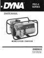
OWNERS MANUAL
MODELS DX3200, CSADX3200
225 South Cardova Avenue
Le Center, Minnesota 56057
READ AND UNDERSTAND ALL INSTRUCTIONS IN
THE MANUAL BEFORE STARTING AND OPERATING
THE GENERATOR SET.
USING THIS MANUAL
Congratulations on your choice of an ENERGX generator set. You have selected a high-quality, precisionengineered generator set designed and tested to give
you years of satisfactory portable service.
To get the best performance from your new engine
generator set, it is important that you carefully read and
follow the operating instruction in this manual.
Should you experience a problem please follow the
"Things To Check" near the end of this manual. The
warranty in the back of this manual describes what you
can expect from ENERGX should you need service
assistance in the future.
TABLE OF CONTENTS
PAGE
INTRO . . . . . . . . . . . . . . . . . . . . . . . . . . . . . . . . . . . . . .I
ENERGX WARRANTY . . . . . . . . . . . . . . . . . . . . . . . . .I
GUIDE TO PRODUCT SAFETY . . . . . . . . . . . . . . . . A1
BASIC INFORMATION . . . . . . . . . . . . . . . . . . . . . . . B1
Specifications.. . . . . . . . . . . . . . . . . . . . . . . . . . B1
Intended Uses . . . . . . . . . . . . . . . . . . . . . . . . . . .B1
Restricted Uses . . . . . . . . . . . . . . . . . . . . . . . . .B1
Unit Capabilities. . . . . . . . . . . . . . . . . . . . . . . . . B1
Where is Everything Located . . . . . . . . . . . . . . B2
PREPARING THE UNIT . . . . . . . . . . . . . . . . . . . . . . C1
Unpacking the unit . . . . . . . . . . . . . . . . . . . . . . C1
Oil Requirements . . . . . . . . . . . . . . . . . . . . . . . . C1
Fuel Requirements.. . . . . . . . . . . . . . . . . . . . . . C1
Battery Installation. . . . . . . . . . . . . . . . . . . . . . . C1
BASIC OPERATION . . . . . . . . . . . . . . . . . . . . . . . . . D l
Initial Start Up . . . . . . . . . . . . . . . . . . . . . . . . . .D l
Starting and Stopping . . . . . . . . . . . . . . . . . . . . D l
Connecting the Loads.. . . . . . . . . . . . . . . . . . . D2
OPERATOR MAINTENANCE . . . . . . . . . . . . . . . . . . E l
Engine Care . . . . . . . . . . . . . . . . . . . . . . . . . . . . E l
Generator Care . . . . . . . . . . . . . . . . . . . . . . . . . . E l
Unit Cleaning . . . . . . . . . . . . . . . . . . . . . . . . . . . E l
Things to Check before you call for Service . E2
Wiring Diagram.. . . . . . . . . . . . . . . . . . . . . . . . . E3
,
PROPER USE AND INSTALLATION
You must be sure your new engine generator set is:
* Properly serviced before starting
* Operated in a well ventilated area
* Exhaust gases are dispersed safely
* Wired by a qualified electrician
* Operated only for its designed purposes
* Used only by operators who understand its
operation
* Properly maintained
COPY YOUR MODEL AND SERIAL
NUMBER HERE
No other ENERGX generator has the same serial number as yours. It is important that you record the number
and other vital information here, if you should ever need
to contact us on this unit it will help us to respond to
your needs faster.
MODEL
................
SERIAL NUMBER..
......
DATE PURCHASED . . . . . .
DEALER. . . . . . . . . . . . . . . .
\
GUIDE TO PRODUCT SAFETY
This engine generator set has been designed and
manufactured to insure your personal safety. Improper
use can result in potential deadly hazards; from electrical shock, exhaust gas asphyxiation, or fire. Please
read all safety instructions carefully before installation
or use. Keep these instructions handy for future reference. Take special note and follow all warnings on the
unit and in the manuals.
CAUTION: Possible Damage to Equipment. CAUTION notes indicate any condition or practice, which if not strictly
observed or remedied, could result in
damage or destruction of the equipment.
-
3. DEADLY EXHAUST GAS Exhaust fumes from any
gasoline engine contain carbon monoxide, an odorless and deadly gas that must be mixed with fresh
air.
A. Operate only in well ventilated areas.
B . Never operate indoors.
C .Never operate the unit in such a way as to allow
exhaust gases to seep back into closed rooms (i.e.
through windows, walls or floors).
4. NOISE HAZARD - Excessive noise is not only
tiring, but continual exposure can lead to loss of
hearing.
A. Use hearing protection equipment when working
around this equipment for long periods of time.
B. Keep your neighbors in mind when permanently
installing this equipment.
a
WARNING: ~e'rsonalDanger. WARNING notes indicate any condition or
practice, which if not strictly observed,
could result in personal injury or possible loss of life.
.
.
1. ELECTRIC SHOCK - The output voltage present in this equipment can cause a fatal electric
shock. This equipment must be operated by a
responsible person.
A. Do not allow anyone to operate the generator without proper instruction.
B. Guard against electric shock.
C. Avoid contact with live terminals or receptacles.
D. Use extreme care if operating this unit in rain or
snow.
E. Use only three-prong grounded receptacles and
extension cords.
F. Be sure the unit is properly grounded to an external ground rod driven into the earth.
2. FIRE HAZARD - Gasoline and other fuels always present a hazard of possible explosion andlor fire.
A. Do not refuel when the engine is running or hot.
Allow the engine to cool at least two minutes
before refueling.
B. Keep fuel containers out of reach of children.
C. Do not smoke or use open flame near the
generator set or fuel tank.
D. Keep a fire extinguisher nearby and know its proper use. Fire extinguishers rated ABC by NFPA
are appropriate.
E. Store fuel only in an approved container, and only in a well-ventilated area.
5. CLEANLINESS - Keep the generator and surrounding
area clean.
A.Remove all grease, ice, snow or materials that
create slippery conditions around the unit.
B-Remove any rags or other material that could
create potential fire hazards.
C .Carefully wipe up any gas or oil spills before starting the unit.
D .Never allow leaves or other flammable material to
build up around the engine exhaust area.
6. SERVICING EQUIPMENT - All service, including the
installation or replacement of service parts, should
be performed only by a qualified technician.
A. Use only factory approved repair parts.
B. Do not work on this equipment when fatigued.
C.Never remove the protective guards, cover or
receptacle panels while the engine is running.
D .Use extreme caution when working on electrical
components. High output voltages from this equipment can cause serious injury or death.
E. When servicing this unit always avoid hot mufflers,
exhaust manifolds, and engine parts. They all can
cause severe burns instantly.
F. Installing and wiring a home-standby generator is
not a "do it yourself" project. Consult a qualified,
licensed electrician or contractor. The installation
must comply with all national, state, and local
codes.
SPECIFICATIONS
MODEL
Generator
Surge Watts
Continuous Watts
AC Volts
AC AMPS
DC Volts
DC AMPS
Receptacles
NEMA 5-15 (120V)
NEMA 5-30 (120V)
12 Volt DC
Engine
Size
Model
TYpe
Fuel Capacity
Fuel Consumption
full Load
Starting System
Stop System
Low Oil Shutdown
Muffler
Complete Unit
Weight (dry)
Dimensions LxWxH
Owner Must
Provide
Fuel
Oil Type
Oil Capacity
DX3200
CSADX3200
3200
2800
120
23.3
12
10
3200
2800
120
23.3
12
10
4
2
1
1
1
5H P
5H P
FA210
FA210
See Engine For Type
3/4 GAL
3/4 GAL
0.75 glhr
0.75 glhr
Recoil
Switch on Engine Shroud
Standard
Standard Muffler with Spark
Arrestor
99 LBS
24x15~14
99 LBS
24x15x14
the engine and the generator. Small compartments
will also develop hot spots where there is very little
air flow and may cause a fire.
3. DO NOT attempt to operate this unit at 50 cycles.
These units are designed and governed to operate
at 60 Cycles only. Special units are available for 50
cycle operation.
UNIT CAPABILITIES
1. Generator Connections - These generators are equipped with a single output power winding. This design
will give the owner full rated generator output from
a SINGLE 120 volt outlet.
The battery charging circuit on the DX3200 is a
center tapped off the standard 120 volt winding. On
the CSADX3200 the battery charging circuit is
separate winding on the armature. This output is
then run through a half wave bridge rectifier where
the current is changed from AC to pulsing DC current. The open circuit charging voltage as measured
with a DC meter or a volt-ohm meter will read approximately seven (7) volts. The peak voltage will be
over 16 volts in order to charge the battery. When
the generator is connected to a 12 volt battery, the
battery level voltage will immediately increase about
0.5 volts showing that the battery is being charged.
A DC ammeter in series with the generator output
will indicate a current reading approximately equal
to the DC nameplate rating if the battery is discharged.
Unleaded Gasoline
SAE30 SC Class. See engine
manual for additional info.
.64 US qt.
.64 US qt.
INTENDED USES
1. These engine generator sets have been designed for
portable use. Receptacles are provided in the control panel on the generator for you to plug in your
loads (portable appliances and tools). These generators are designed with full power capabilities. See
unit capabilities for further explanation.
2. These units require large quantities of fresh air for
cooling of both the engine and the generator. Fresh
air is drawn from both the engine end and the generator end and is exhausted at the center of the unit.
For safety, long life and adequate performance,
these units should never be run in small compartments without positive fresh air flow.
RESTRICTED USES
1. DO NOT remove from the cradle assembly. Removal of the generator from the cradle assembly. may
cause excessive vibration and damage to the engine
generator set.
2. DO NOT install and operate these portable generators in small compartment. (i.e. generator compartment of vehicles, motor homes or travel trailers)
These compartments will not allow enough free flow
fresh air to reach the engine generator set for cooling and will allow the unit to overheat damaging both
FIG B1
The following currents (measured in amps) are produced at 120 volts and 240 volts for models shown.
AMPS @
120 VOLT
RECEPTACLE ID
MODEL
DX3200
CSADX3200
23.3
12 VOLT
'"'
SPECIFICA TlONS (continued)
2. Starting Electric Motors - Electric motors require
much more current (amps) to start them than to run
-them. Some motors, particularly low cost split-phase
motors are very hard to start and require 5 to 7 times
as much current to start them as to run them. Capacitor motors are easier to start and usually require
2 to 4 times as much current to start them as to run
them. Repulsion Induction motors are the easiest to
start and usually require 11/2 to 2% times as much
current to start them as to run them.
Most fractional horsepower motors take about the
same amount of current to run them whether they
are of Repulsion-Induction (RI), Capacitor (Cap), or
Split-Phase(SP) type. The chart below shows the approximate current required to start and run various
types of sizes of 120 volt 60 cycle electric motors
under average load conditions.
RUNNING STARTING AMPS
RI
SP
CAP
HP AMPS
116
3.2
16 TO 22
6 TO 13 5 TO 8
114
4.5
22 TO 32
9 TO 18 7 TO 12
113
5.2
26 TO 35 10 TO 21
8 TO 17
112
7.2 NOT MADE 14 TO 29 11 TO 18
1
13.0 NOTMADE26TO52 20TO33
The figures given above are for average loads such
as a blower or fan. If the electric motor is connected
to a hard starting load such as an air compressor,
it will require more starting current. If it is connected
to a light load, or no load such as a power saw, it
will require less starting current. The exact requirement will also vary with the brand or design of the
motor.
3. Motor Starting Capacity - listed below you will find
the motor starting capability of your engine generator set.
Model
CSADX1000
(code "G" capacitor start)
HP
Trying to start a larger motor or a higher code (ie.
J or K) motor may result in damage to both the generator and the electric motor especially 120 volt
motors.
WHERE IS EV'ERYTHING LOCATED
L
0
-
1.
2.
3.
4.
5.
6.
7.
8.
Rewind Start Grip
Fuel Fill
Choke Lever
Air Filter
Stop Switch
Muffler
Spark Plug
120 Volt Duplex Receptacle
9.
10.
11.
12.
Ground Lug
Circuit Breaker
Battery Charging Receptacle
Low Oil Sensor
*Oil Fill Same Location
Opposite Side
13. Oil Drain Plug
14. Low Oil Control Module
PREPARATION INSTRUCTIONS
]-[
OUT OIL. Failure to maintain the engine
UNPACKING - When you unpack your new ENGINE
GENERATOR be sure to remove all the information
sheets and manuals from the carton. Also be sure that
any accessories (such as battery rack) ordered with the
generators have also been received.
1. This power plant was in good order when shipped.
Inspect the power plant promptly after receiving it.
If damage is noted, notify the transportation company immediately; request proper procedures for filing a "concealed damage" claim. Title to the equipment and responsibility forfiling claim rests with you
when a generator is sent F:O.B. shipping point. Only
you the customer, can legally file a claim.
2. Before proceeding with the preparation of your new
engine generator set for operation, take a few
minutes to insure that the unit you have received is
the correct model and review the specification pages
in this manual to insure that this unit meets your job
requirements.
3. After removing the engine generator from the carton
locate and install the four rubber feet shipped loose.
The cradle has been predrilled for the installation of
these rubber feet.
UNlT PREPARATION - Before your engine generator
was shipped from our factory it was fully checked for
performance. The generator was load tested to its full
capacity, and the voltage and frequency were carefully checked and adjusted.
1. Lubrication - Before starting the engine, fill the crankcase to the proper level with a good quality oil. The
recommended grade of oil and quantity of oil required
is listed in both the engine operators manual and in
the specifications section (page B1) of this manual.
The importance of using the correct oil, and keeping the crankcase full cannot be overemphasized.
Engine failures resulting from inadequate or improper
lubricant are considered abuse and are not covered
by Energx or the engine manufacturer's warranty.
2. Gasoline fuel - When using gasoline always use a
good grade of unleaded fuel. Leaded gasoline may
be use if unleaded is not available. Gasoline containing alcohol, such as gasohol is not recommended.
However if gasoline with alcohol is used, it must not
contain more than 10 percent Ethanol and must be
removed from the engine during storage. DO NOT
use gasoline containing methanol. Always insure
that the fuel is clean and free of all impurities.
-
a
FIRE DANGER
Gasoline and its fumes are VERY explosive when proper precautions are
not taken.
Never use gasoline that has been stored for an
extended period of time as the fuel will lose its
volatile properties and you will be left with only the
varnish residue. This varnish like substance will clog
the carburetor and will not burn properly. The use
of a fuel additive, such as STA-BIL, or an equivalent,
will minimize the formation of fuel gum deposits. If
a unit has been out of operation for an extended
period of time its best to drain old fuel from the
engine and replace with fresh fuel before attempting
to start.
BASIC OPERATION
-
INITIAL START UP - Use the following checklist to verify
the correct preparation of your engine generator before
starting.
On All Units Check:
1. Engine oil, fill as required with correct grade and
quantity.
2. Check fuel level and fill as required with clean fresh
fuel.
3. Visually check unit for loose parts.
added to gasoline in the fuel tank of the engine,
or to gasoline in a storage container.
1. Remove the remaining fuel from the fuel tank.
2. Start the engine and allow it to run until all the
fuel in the carburetor and the fuel lines has been
used up and the engine stops.
3. While the engine is warm drain oil and refill with
fresh oil.
4. Remove the spark plug, pour approximately 112
ounce (15 cc) of engine oil into the cylinder and
crank slowly to distribute oil. Replace spark plug.
5. Clean dirt and chaff from cylinder, cylinder head
fins, blower housing, rotating screen and muffler
areas. Store in a clean and dry area.
STARTING AND STOPPING - The throttle control on
these generators is preset and locked to operate at 3600
RPM (nominal) with no load speed set at 3690 RPM. Only a trained service technician should be allowed to adjust this speed setting. See "Operating Speed" section
for additional information.
1. Manual starting - Refer to the engine manual for additional starting, operating, and stopping instructions.
A. Turn the stop switch to run.
B. Move the choke to the full on position. A warm
engine will require less choking than a cold engine.
C. Grasp starter grip and pull slowly until starter
engages, then pull cord rapidly to overcome compression, prevent kickback and start the engine.
Repeat if necessary.
D. When the engine starts, open the choke gradually.
E. The engine should promptly come up to operating
speed.
OPERATING SPEED -The engine-generator must be run
at the correct speed in order to produce the proper electrical voltage and frequency.
A
1. All engines have a tendency to slow down when a
load is applied. The governor on the engine is designed to hold the speed nearly constant. When the
electrical load connected to the generator is increased, the engine is more heavily loaded, and as a result
the speed drops slightly. This slight decrease in
speed, together with the voltage drop within the generator itself, results in a slightly lower voltage when
the generator is loaded to its full capacity than when
running no load. The slight variation in speed also affects the frequency of the output current. This frequency variation has no appreciable effect in the
operation of motors, lights and most appliances.
However, electronic equipment and clocks will be affected if correct RPM is not maintained. See load vs.
Output chart.
Although individual units and models may vary
slightly, the normal voltage and frequency of the
engine-generatorsdescribed in this book are approximately as follows, under varying loads:
2. Starting Hints
A. Cold weather
1. Be sure to use the proper oil for the temperature
expected.
2 .A warm battery has much more starting capacity than a cold battery.
3.Use fresh winter grade fuel. Winter grade
gasoline has higher volatility to improve starting. Do not use gasoline left over from summer.
4. A slightly richer fuel mixture will usually improve
cold starting.
B. Hot weather
1. Be sure to use the proper oil for the temperature expected.
2. Use only summer blended gasoline. Using gasoline left over from winter may cause the unit
to vapor lock, because of the higher volatility of
the winter fuel.
3. Do not over-choke the unit.
-
The output voltage should be checked
to insure the generator is working properly prior to connecting a load to the
generator. Failure to do so could result
in damage to equipment plugged into
the unit and possible injury to the individual.
I
LOAD vs. OUTPUT
Generator Frequency
Speed
Applied*
Half
3600
60.0
3510
58.5
*Portion of plant's rated output current.
I Full
3. Stopping and Storage
A. For gasoline units turn the stop switch to stop.
B. Before extended storage (over 30 days) certain
precautions must be taken to ensure the fuel
doesn't deteriorate and clog the fuel system. Note:
The use of fuel additive, such as STA-BIL, or an
equivalent, will minimize the formation of fuel gum
deposits during storage. Such an additive may be
Voltage
Recpt.
120V
115V
2. The speed of the engine was carefully adjusted at
the factory so that the generator produces the proper voltage and frequency. For normal usage, the
speed setting should not be changed. If the generator is being run continuously on a very light load,
it is often advisable to lower the operating speed
Dl
BASIC OPERATlON (continued)
slightly. Whenever making any speed adjustments
check the unit with a voltmeter or tachometer and be
sure the speed is neither too high or low.
The engine must be run at the specified speed at
all times. Lower voltage may damage both the
generator and any load connecting to it. Running the
engine at excessively high speeds results in high
voltage, which may significantly shorten the life of
appliances being used.
3.Output voltage should be checked periodically to ensure continued proper operation of the generating
plant and appliances. If the generator is not equipped with a voltmeter, it can be checked with a portable meter. Frequency can be checked by using an
electric clock with a sweep second hand. Timed
against a wrist watch or a stop watch the clock should
be correct within 1- 2 seconds.
+
CONNECTING THE LOADS
1. Applying The Load -Allow the engine to warm up for
two or three minutes before applying any load. This
will allow the engine to reach normal operating temperature and oil to circulate throughout the engine.
A short warm-up time will permit the engine to work
more efficiently when the load is applied and will
reduce the wear in the engine, extending its life.
A. Receptacles have been provided on the control
panel for your load connections. The loads
should be applied gradually. If a large motor is
being started or multiple motors are being
started, they should be started individually and
the largest should be started first.
B. Most electric tools and appliances will have the
voltage and amperage requirements on their individual nameplates. When in doubt consult the
manufacturer or a local electrician. The nameplate
amperage rating for electric motors can be misleading, see Starting Electric Motors in section B.
C.These engine generator sets are inherently self
regulating based on engine speed. The engine
governor will automatically adjust itself to the
load. No harm to the generator will result if it is
run with no load connected.
D. Proper utilization of the receptacles located on the
control panel is necessary to prevent damage to
either the receptacles or the generator. The generator is a limited source of electrical power, therefore pay special attention to the receptacle and
generator ratings. The nameplate rating can be obtained through a combination of receptacles or a
single receptacle as long as the receptacle
amperage rating is not exceeded. Both the 120 and
240 volt receptacles can be utilized at the same
time. See section B for proper load separation.
2. Grounding - All units must be grounded.
A .Drive a 3/4 or 1'' copper pipe or rod into the ground
close to the engine-generator set. The pipe must
penetrate moist earth. Connect an approved
ground clamp, to the pipe. Run a no. 10 Awg wire
from clamp to the generator ground lug or the battery negative terminal. Do not connect to a water
pipe or to a ground used by a radio system.
3. Connecting the Battery - Enclosed with your new
generator set you will find a 12V DC connector, leadwire and battery clip assembly. This lead wire set
is provided for your use in charging 12 volt batteries.
Located on the front panel is a 12 volt receptacle.
To charge your batteries plug the lead wire assembly
into this receptacle and attach the battery clips to
the battery. The red clip is positive and the black clip
is negative. If the positive and negative leads are accidentally shorted, or are incorrectly connected to
the battery, the automatic resetting DC circuit
breaker in the generator will trip to protect the generator and your battery. Once the short is removed the
circuit breaker will reset itself in about 5 seconds.
A
PERSONAL DANGER
Lead acid batteries produce explosive
hydrogen gas when charging. Keep
sparks, flames, and burning cigarettes
away from the battery. Ventilate the
area when charging or using the battery
in an enclosed space. Lead acid batteries contain sulfuric acid, which causes
severe burns. If acid contacts eyes, skin
or clothing, flush well with water. For
contact with eyes, get immediate medical attention.
LOW OIL SHUTDOWN SYSTEM
KAWASAKI Powered Generators - These engine generator sets come equipped with a standard Kawasaki
low oil shut-down system.
A.This low oil shut-down system will automatically
stop the engine well before the oil level reaches a
danger point. This feature is designed to prevent
costly repairs and downtime.
B.The low oil shut-down system consists of a float
switch and a low oil module to monitor the oil level
in the crank case. The float switch is mounted in the
engine crank case between the engine and the
generator end bracket. The module is mounted on
the engine. The module monitors the oil level via the
float switch; if the oil level is low it will short out the
engine ignition and shut the engine off. If the oil level
is low when the engine is started, the engine will
start and run for about three (3) seconds and shutdown. This indicates that the oil level is low and
must be completely refilled before starting.
C. Use of this low oil shut-down system on applications
that are subject to shock, bumping or severe angles
of operation (in excess of 15 degrees) should be
avoided. This is especially true if an unexpected
shutdown would cause a safety hazard or serious
inconvenience for the operator. To disable the shutdown system disconnect the wire running from
under the engine shroud to the control module
mounted on the engine.
OPERATOR CARE AND MAINTENANCE
-
ENGINE CARE - If major engine service or repair is required contact an Authorized Engine Service Center.
The manufacturer of these engines has established an
excellent world-wide engine service organization. Engine service is very likely available from a nearby authorized dealer or distributor. Check the yellow pages of
your local telephone directory under "EnginesGasoline" for the closest engine repair center or ask
the dealer from whom you purchased the power plant.
1. Oil Changes
Change the oil after the first 20 hours of operation
and every 100 hours thereafter under normal operating conditions. Change engine oil every 50 hours
of operation if the engine is operated under heavy
load, or in high ambient temperatures.
A. Remove oil drain plug at base of the engine and
drain the oil with the engine warm.
B. Replace oil drain plug.
C .Remove oil filler plug and refill with new oil. Refer
to the table in the engine manual for the proper
grade of oil based on your operating temperature.
D. Replace filler plug.
-
2.Checking the Oil Level. The oil level must always be
checked before the engine is started. Take care to
remove any dirt or debris from around the oil fill plug
before removing. Be sure the oil level is maintained.
FILLTO POINT OF OVERFLOWING or on units with
the extended oil fill to the "FULL" mark on the
dipstick.
If the engine generator should fail to start and run,
check to be sure that the low oil protection system
has not been activated by a low oil condition.
3. Servicing Air Cleaners
A .Cleaning Air Cleaner Element - clean and re-oil
foam air cleaner at three month intervals or every
50 hours, which ever occurs first. Service more
often under dusty conditions.
1. Remove air cleaner cover and take the element
out.
2. Wash element in kerosene or liquid detergent
and water.
3. Wrap foam pre-cleaner in cloth and squeeze
dry4 . Saturate in engine oil. Squeeze to remove excess oil.
5. Install element in the air cleaner body. Be sure
to install with the surface marked "inside" facing toward the carburetor.
4. Spark Plug - Clean and reset gap at .030" every 100
hours of operation. Do not blast clean spark plug.
Clean by scraping or wire brushing and washing with
a commercial solvent. Poor spark will occur if terminal does not fit firmly on spark plug. If this happens re-form the terminal to fit firmly on spark plug
tip.
GENERATOR CARE - Proper care and maintenance of
the generator is necessary to insure a long trouble free
life.
1. Exercising The Generator - The generator should be
operated every three to four weeks. It should be operated for a period of time sufficient to warm the unit
up and to dry out any moisture that has accumulated
in the winds. If left this moisture can cause corrosion in the winding and on the slip rings. Frequent
operation of the engine generator set will also insure
that the set is operating properly should it be needed
in an emergency.
2. Generator Maintenance - Any major generator service including the installation or replacement of
parts should be performed only by a qualified electrical service man. USE ONLY FACTORY APPROVED
REPAIR PARTS.
A. Bearing - The bearing when used in these generators is heavy duty double sealed ball bearing. It
requires no maintenance or lubrication.
B. Brushes - Under ordinary circumstances brushes
will operate for long periods without requiring replacement. They should be inspected after 1000
hours of operation and every 100 hours thereafter.
When operating in dusty conditions check more
often to insure the slip ring and brush contact
area is clean and not wearing excessively.
C. Receptacles - Quality receptacles have been utilized. If a receptacle should become cracked or
otherwise damaged, replace it. Using damaged or
cracked receptacles can be dangerous both to the
operator and to the equipment.
CLEANING - Remove dirt and debris with a cloth or
brush. DO NOT use high pressure spray to clean either
the engine or the generator. This high pressure spray
could contaminate the fuel system and the generator
components.
1. Keep the air inlet screen on both the engine and
generator free of any dirt or debris to insure proper
cooling. At least yearly remove the blower housing
on the engine and clean the chaff and dirt out of the
engine cooling fins and flywheel. Clean more often
if necessary, failure to keep these areas clean may
cause overheating and permanent damage to the
unit.
2. Periodically clean muffler area to remove all grass,
dirt and combustible debris to prevent a fire.
3. On engine mufflers equipped with spark arresters, the
spark arrester must be removed every 50 hours for
cleaning and inspection. Replace if damaged.
OPERATOR CARE AND MAINTENANCE (continued)
-
THINGS TO CHECK
Sometimes problems can be easily solved by checking a few basic things. Check the chart below before
you call or take your unit to a service center. It could
save you time and money.
Problem
Won't Start
Voltage too low
Voltage too high
Possible Causes
*Check and clean spark plug
*Check fuel level
*Fuel turned on.
Dead battery
*Defective start switch.
*Check for proper engine
speed
*Generator overloaded
*Defective rectifier
*Defective Armature
*Defective Field Coil
*Engine speed is too high
Problem
Generator
overheating
No output voltage
Battery not
re-charging
Possible Causes
*Overloaded
*Insufficient ventilation
*Short in load (disconnect)
*No residual magnetisim in
generator
*Defective armature
*Defective field coil
*Defective Brushes
*Shorted condenser
*Shorted rectifier
Defective receptacle
*Defective charging circuit
on engine
EXCITATION CIRCUIT
"BOOST" CIRCUIT
POWER CIRCUIT
BATTERY CHARGE
'FULL POWER
ARMATURE
WINDINGS
RECEPTACLES
EXCITATION ClRCUlT
CAYS I
-
I I","
RECTIFIER
7
YRUSHES
SHUNT
FIELD
COILS
POWER CIRCUIT
SLIP RINGS
\
d
BATTERY CHARGE
& ? . CIRCUIT
'FULL POWER
WINDING
NEUTRAL
ciln
OUTPUT
mnn,,
BAnERY CHARGE
"ECTIFIER
AC
4'
120 VOLT
CIRCUIT BREAKER 9
25 AMP 120 VOLT
9 CIRCUIT BREAKER
+
ARMATURE
WINDINGS
BATTERY
CHARGING
WINDING
"tluuti I '.
"BOOST"
AUTO RESET
CIRCUIT BREAKER
N
i
NOT USED
A
-
A
I