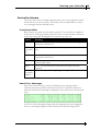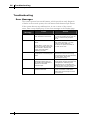
1
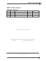
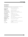
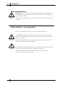
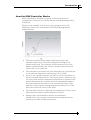
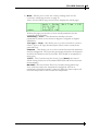
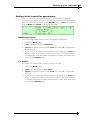
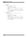
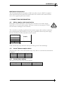
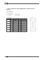
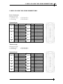
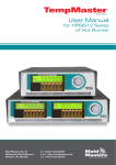
User Manual for HRS6/12
Series of Hot Runner
DMS Ltd,
Unit 11, Blenheim Road,
Cressex Industrial Estate, High
Wycombe, Bucks, HP12 3RS
Tel: +44 (0)1494 523811
Fax: +44 (0)1494 452898
HRS6/12 Users Manual
Amendment Record
HRS6/12 Users Manual
Amendment Record
Issue
Author
Authorised
Date
Amendments
1.0
Dec 2005
Initial Provisional Issue
DH
SK
1.1
Feb 2006
First Issue
DH
SK
1.2
July 2007
HRS12 Variant Added
DH
SK
Copyright (c) DMS Developments 2006
This manual is intended for use with the HRS-6/12 Series controller
(Serial No…………………….) with which it was supplied.
Our policy is one of continuous improvement and we reserve the right to alter product specifications at
any time without giving notice.
Issue 1.2
2
HRS6/12 Users Manual
3
4
HRS6/12 Users Manual
Contents
Contents
HRS6 Users Manual ............................................................................................ 3
Introduction ........................................................................................................ 5
Setting up your controller................................................................................. 16
Running your Controller .................................................................................. 22
Troubleshooting................................................................................................ 26
APPENDIX A..................................................................................................... 28
Index ................................................................................................................. 32
Introduction
Specification
Introduction
Specification
The following are general specifications. The actual controller/console supplied may
have contractual variations and differ in some specified options.
Supply Voltage
415v 3 phase 50/60Hz with neutral
Supply Voltage
Tolerance:
± 20% supply voltage swing.
Supply Protection:
Miniature Circuit Breaker
Overload Protection:
High Speed Semiconductor Fuse Links
Mains Voltage Output:
Burst fired, zero crossover & phase-fired soft start
Output Current:
15 A max
Control range:
0 - 472 Centigrade (Celsius).
Temperature scale:
Centigrade (Celsius) or Fahrenheit
Control Method:
Open or closed loop with HR software.
Thermocouple input:
Type 'J' or Type 'K'
Front panel LED
Indicators
Normal running, high and low temperature Alarm
T/C & Heater Tool
connector
Harting type Han A or equivalent.
Input Device
"Turn & Press" control wheel
Display
4 x 40 characters, LCD Screen (one for HRS6 and two
for HRS12
Case: HRS-6
Metal case 32w x 14h x 37d cm
Issue 1.2
2
HRS6/12 Users Manual
5
6
Introduction
Safety Instructions
Safety Instructions
DO NOT enter the cabinet without first ISOLATING the supplies –there
are unguarded terminals inside the cabinet which may have a dangerous
potential across them.
Where a three-phase supply is used then this potential may be at 415 volts
or higher.
Safety Notices - an explanation
Within this manual, safety instructions are marked as follows:
A WARNING symbol and message, shown here, identifies where there
may be a hazardous situation which, if not avoided, may result in death or
injury to personnel.
Most warnings pertain to electrical aspects and you must comply with
them to minimise any personal danger.
A CAUTION warning identifies where there may be a hazardous situation
which, if not avoided, may result in damage to property.
Caution warnings present no personal danger, but may cause the
equipment to fail or lose its memory.
Introduction
Where to use this equipment
Where to use this equipment
DMS Hot Runner temperature controllers are designed for use in the
plastic injection moulding industry as temperature controllers for third
party hot runner systems as commonly used in mould tools. The
controllers must not be used in residential, commercial or light-industrial
environments. Furthermore, they must not be used in an explosive
atmosphere or where there is a possibility of such an atmosphere
developing.
They should be installed in a clean dry environment where the ambient
conditions do not exceed the following limits: •
Temperature
•
Relative Humidity 90% (non-condensing)
0 to +35°C.
Controller — Tool Connections
The various connections to the system using the cables supplied with the
equipment are specified Appendix A.
Equipment failure through mis-wiring
Before you energise the system, pay special attention to how the supply to
your controller is wired and how it is connected to the mold.
Lack of attention to detail causes errors such as:
• incorrect wiring of mains supply phases into the controller
•
crossing heater supply feeds with thermocouple inputs (although this
error can be eliminated by the adoption of HASCO Standard
connections)
In such cases wiring errors have caused equipment failure.
DMS cannot be responsible for damage caused to the controller by
customer wiring and/or connection errors.
Controller Power Supplies
The control cabinet can be manufactured to accept a wide range of supplies
and sequence of phases. Refer to the serial plate in the controller cabinet for
confirmation of the supply requirements. If the local supply is outside the
specified range please contact DMS Systems for advice.
Tel: +(0) 44 494 523811
Issue 1.2
2
Fax.: +(0)44 1494 452898.
HRS6/12 Users Manual
7
8
Introduction
Switching On and Off
Switching On and Off
For the HRS models, the main Power Switch is an MCB at the rear of the
cabinet. The breaker is sufficiently rated to disconnect the total load
current and is used for switching “On” and “Off”.
“0 ° C/F” or “0% Power” is NOT Switched Off
The heat of a nozzle is proportional to the applied current. Setting any
zone to zero degrees temperature, or 0% power, means that only the
current is reduced to zero. However, the current-control is not a breakingcontact switch but a semi-conductor device known as a Triac. This means
that, at zero current, there may still be some voltage at the nozzles.
On a 3-phase “star” supply with a neutral, the triac is on the live side of the
supply – this keeps residual voltage to a low value. However, you should
ALWAYS isolate the controller before you open up a controller to examine
any wiring or change fuses. Remember that, with respect to the mains
supply, “0% power is NOT “Off”.
Introduction
The HRS 6 & 12 Controller
The HRS 6 & 12 Controller
The HRS is a two-part case with the display and control functions on the front
while the input and output cables and the main switch are mounted on the rear
panel.
Both the output load fuses and the input thermocouple fuse are mounted on the
main circuit board(s). If you need to check or replace a fuse then you should
isolate the controller from any electrical supply before you open the case.
Controller Cards
There are three boards mounted inside the HRS6 cabinet. Two boards are
fixed to the front facia; one to house the main LCD display unit and the
second is an interface for all the LED display alarms.
The third board controls the zone temperatures, and it has four main
components:
• thermocouple amplifiers,
• CPU,
• multi-voltage output triacs,
• power supply.
The HRS12 has a similar construction but uses two LCD displays and two
LED interface boards. The two main control boards differ in that only one
board has the common power supply, while the other has all the
thermocouple inputs and amplifiers. Both main boards have six output
control circuits and each board has its own CPU to control those six
circuits.
Thermocouple Amplifiers
The Thermocouple amplifier used in the HRS-6/12 controller can be configured
for use with either J or K-type thermocouples. You can set this option on the
“Mode” page.
Central Processor Unit (CPU)
The CPU provides the following facilities: -
Issue 1.2
2
•
closed and open loop control of the zones,
•
communicates settings and thermocouple readings over the data link
to the display micro-processor
•
checks for alarm conditions, including blown fuse, incorrect
thermocouple wiring, zone over temperature condition, heater not
responding to controller output and generates alarm information for
the display page,
•
controls the output power to the triacs using a number of self-tuning
algorithms,
•
monitors the thermocouple every 20 milliseconds
HRS6/12 Users Manual
9
10
Introduction
The HRS 6 & 12 Controller
Input and Output Supplies
The power supply to the cabinet is via a cable at the rear of the panel that
is fitted with a 3-phase 32A plug.
Connections to the tool are made through one or two cables which carry
the heater supplies and thermocouple connections. Tool-to-Controller
terminations are made through a Harting type Han E connectors and the
wiring details are shown in Appendix A.
Introduction
How the DMS Controller Works
How the DMS Controller Works
DMS controllers are designed to perform in closed and open loop
configurations. However, we consider that the normal operating mode is
closed loop.
Whenever the controller is set to start, the system goes into a selfcalibration routine. This is illustrated in the following diagram and
explained below.
Issue 1.2
2
•
The zone controller slowly ramps up the heater power and
simultaneously looks for a positive temperature change at the
thermocouple input. The controller verifies the actual rate of rise
against a predetermined value. Power is slowly increased until the
correct rate of rise is achieved.
•
The controller now increases the zone temperature at a constant rate
of rise until the temperature reaches about 110°C (230°F).
•
At 110°C the controller performs a 'Load Test' on the zone heater to
check its thermal characteristics. The output power is reduced to zero
for a test period and the temperature monitored for a response. From
all this information, the controller has built mathematical model of
the heater characteristics and so it can automatically select a Fast,
Medium or Slow response heating program that suits the tool. This
allows more efficient control of the zones.
•
The controller continues to ramp up the temperature to the set point,
which should be achieved with minimum over-shoot.
•
Having built a virtual model to map the tool and heater
characteristics, the controller can maintain the temperature at an
accurate point with virtually no deviation.
HRS6/12 Users Manual
11
12
Introduction
Watchdog feature
Watchdog feature
The Controller card CPU has a 'watchdog' timer that has to be reset by the
system every 3 milli-seconds. If for any reason the software fails to reset
the timer, the zone power is set to zero to protect the tool against overheating. The controlling card resets to the auto-tune start position and
power is increased in progressive steps until correct temperature control is
re-established.
Safety Memory Check
This controller uses flash memory to store all your settings such as
temperatures, limits and alarms. There is an extremely low small risk that
an interruption may cause any of these settings to alter and, if such an
event should occur, then there must be no risk to the equipment.
To ensure that this cannot happen there is a safety memory-check facility.
This checks to see that no value has been changed since the last time that
the controller was used. If this facility detects that any setting is different,
then it protects your system by automatically erasing every single stored
setting within its memory. If such a rare occurrence happens to your
controller then you will be met by the following message when you switch
on:
"CAUTION SYSTEM RAM ERROR
Stored values HAVE been ERASED"
If you read this then you need reset all appropriate settings. This basic task
is described in the next chapter of this manual. The task is easier if you
have all the correct settings written down in a safe place.
CAUTION
DMS recommends that a hard copy of all the controller and tool
settings is saved in a safe place.
The HRS Console
Screen
The HRS Console
Screen
40 x 4 LCD Screens display all the necessary information which is divided
into four rows to normally show:
Set temperature, Actual temperature, Power level, Speed Setting and, in the
bottom left, the page “Name”.
Front-panel Status Indication
There are 6 LED indicators below each channel to show its status. From the
top there are
Red
Green
Blue
The temperature is above the upper limit.
The controller is operating normally.
The temperature zone is below the lower limit.
Red (T/C)
There is no detected Thermocouple input.
Red (fuse)
The output fuse has ruptured.
Amber (load) The system is delivering output load current.
The Turn-&-Press control wheel interface.
All the control and setup functions are accessed through the Turn-&-Press
wheel.
The HRS12 has two screens with one Turn-&-Press wheel, as you scroll
laterally through the zones then the control will move across from one
page to the other.
As you [Turn] and [Press] the wheel, the screen confirms your selected
function by highlighting the last character of the required function with a
blinking square.
As you turn the wheel, it has an automatic accelerate action which helps
when setting temperatures. If you turn the wheel quickly, the settings will
alter by a large quantity, but as you turn the wheel more slowly, the
increments are smaller which makes for fine adjustment.
If at any time you stop making changes, and leave the wheel idle for about
10 seconds, then the controller will default back to its previous idle state
with no changes made.
Issue 1.2
2
HRS6/12 Users Manual
13
14
The HRS Console
The Screen Interface
The Screen Interface
The Controller has three main pages that may be seen during normal
Running and during Setting Up, these are named “Display”, “Setup” and
“Mode”. This identity is shown at the bottom left of the page. (on the
HRS12 it is shown only on the left hand screen
To select the different pages, push the wheel so that the page name is
blinking, and then turn the wheel to show the three different pages. Their
function is as follows:
1) Display – Shows the current running conditions for the zones. The
four rows (from the top of the page) show:
Set - the Temperature to which the zone has been set.
Actual - the Temperature which is being currently read on that zone.
Power - the Power level currently being used to maintain that
temperature.
Display – the name of the selected page. However, the bottom row
may also be used to select further parameters for each zone which
includes the auto temperature, the manual power level, the zone alarm
limits and the zone on/Off switch.
2) Setup – Shows the current operational settings for the zones. The four
rows (from the top of the page) show:
Speed – The speed that has been selected for the zone. It may be left as
its optimal AUTO setting or changed to Fast, Medium or Slow, if
required (see page 19 for more details).
Standby – The temperature by which the zone is reduced when a
Standby condition is selected.
Boost – The Temperature by which the zone is temporarily raised
when a Boost condition is selected.
(NOTE: that, during a Boost mode, it is the Boost Time that takes
precedence over Boost Temperature. If the Boost temperature has not
been reached by the time a Boost period expires then the zone reverts
to its normal set temperature rather than staying in Boost in order to
reach the configured Boost temperature.)
Setup – the name of the selected page. However, the information on
the rest of the bottom row helps to setup the other zone parameters
including zone speed, and Boost and Standby temperatures.
The HRS Console
The Screen Interface
3) Mode – Allows you to select the current running mode for the
controller, which may be seen on page 23.
(Note: On the HRS12 only the left screen displays the Mode page.)
Within this page you can also set four overall parameters for the
controller which includes:
Scale Deg – C or F – this determines whether the zone
temperatures, limits etc are shown in degrees Centigrade or degrees
Fahrenheit.
T/C Type – J or K – this allows you to set the controller to work to
either J-Type on K-Type thermocouples. Select either to match the
particular tool.
Contrast – This allows you to set the contrast between the characters
and the background. The lower the percentage the darker the character.
At 100% the characters will be invisible. 50% should be acceptable for
most users.
(NOTE – The Contrast may also be set if you [Press] the control
wheel during Switch-on as the alarms LEDs blink and before the main
menus appear)
Bst Time -This sets a Boost Period (in seconds) during which any
zone, that has some boost temperature configured, will rise in
temperature when Boost mode is selected. When the timer expires, all
the zones drop back to their normal set temperature.
Issue 1.2
2
HRS6/12 Users Manual
15
16
Setting up your controller
What is covered in this section
Setting up your controller
New HRS6/12 controllers are not normally configured at the factory. You
should always check through any new controller to see that its settings are
correct for the tool with which it is about to be used. If you are checking a
new controller, or reconfiguring an older controller to use it with a
different tool or environment, then you may need to refer to this chapter of
the manual.
What is covered in this section
Setting the Controller parameters
(including Boost Time, Temperature scale, Thermocouple Type
and Screen Intensity)
Setting the Tool Parameters
(including Zone Speed Settings, Boost and standby
Temperatures, Zone Alarm Limits, Zone Temperatures)
Setting up your controller
Setting initial controller parameters
Setting initial controller parameters
First you should check the MODE page to see that these settings are
correct for your general use. Once the unit has been switched on select the
page title and push the wheel so that Display blinks. [Turn] the wheel till
you see Mode and [Press] it to engage that page.
Temperature Scale
To set the temperature scale to either Centigrade or Fahrenheit:
1. Select the [Mode] page.
2. [Turn] the wheel to select Scale Deg.
3. [Press] the wheel once more and [Turn] it to select C (Centigrade) or
F (Fahrenheit).
4. If you need to set another function while on this page then [Turn] the
wheel to select that function. Otherwise, if there is no other function
to change then leave the wheel untouched for a short time and it will
return to the Display page.
T/C Sensor
To set the T/C Sensor type to either J-Type or K-Type:
1. Select the [Mode] page.
2. [Turn] the wheel to select T/C Type.
3. [Press] the wheel once more and [Turn] it to select J (J-Type) or K
(K-Type).
4. If you need to set another function while on this page then [Turn] the
wheel to select that function. Otherwise, if there is no other function
to change, then leave the wheel untouched for a short time and it will
return to the Display page.
Issue 1.2
2
HRS6/12 Users Manual
17
18
Setting up your controller
Setting initial controller parameters
Boost Time
To set the overall Boost Time (in seconds):
1. Select the [Mode] page.
2. [Turn] the wheel to select Bst Time.
3. [Press] the wheel once more and [Turn] it to increase or decrease the
Boost Time.
4. If you need to set another function while on this page then [Turn] the
wheel to select that function. Otherwise, if there is no other function
to change, then leave the wheel untouched for a short time and it will
return to the Display page.
Screen intensity
To set the intensity of the characters on the screen (and hence the
legibility):
1. Select the Mode page.
2. [Turn] the wheel to select [Display]
3. [Press] the wheel once more and [Turn] it to increase or decrease the
screen character intensity.
4. If you need to set another function while on this page then [Turn] the
wheel to select that function. Otherwise, if there is no other function
to change, then leave the wheel untouched for a short time and it will
return to the Display page.
Setting up your controller
Configuring Zone settings
Configuring Zone settings
Zone Speed settings
The Speed parameter determines how fast the zone will respond to, or
anticipate, changes in temperature. While there are manual settings of
Slow Medium or Fast, the default setting is Auto. This allows the zone to
run the auto-load sensor program (described on page 11) during its first
start and so determine which of the three manual settings best suits the
load. You can override this automatic selection by selecting one of three
preferred speeds on a zone-by-zone basis, as described here:
1. Select the Setup page.
2. [Turn] the wheel to select Spd on the required zone.
3. [Press] the wheel twice to make the word AUTO, on the top row,
blink then [Turn] it to change the zone speed from Auto to select the
manual speed setting to either FAST, MEDI (Medium) or SLOW then
[Press] the wheel to select that speed.
4. If you need to set another function (Standby or Boost temperature) while
on this page then [Press] the wheel again to select that function.
Otherwise, if there is no other function to change, then leave the wheel
untouched for a short time and it will return to the Display page.
Setting the zone Boost and Standby Temperatures
The Boost and Standby temperatures may be set on a zone-by-zone basis. Both
are set as temperatures above or below the set temperature as opposed to a
specific temperature values. These values can be set as described below:
1. Select the Setup page.
2. [Turn] the wheel to select Spd on the required zone.
3. [Press] the wheel once to make the word Spd, on the bottom row,
blink, then [Turn] it to select either Bst or Stby and [Press] the
wheel once more to make the appropriate setting blink.
4. While Stby blinks, [Turn] the wheel to set the required Standby
temperature reduction, then [Press] to accept the new setting.
5. To follow on and set the Boost temperature [Press] the wheel to
make Spd blink then [Turn] the wheel to select Bst and [Press] once
more.
6. With Bst blinking and the temperature selected, [Turn] the wheel to
raise or lower the required boost temperature.
(Note: in a Boost mode condition, it is the Boost Time that takes
precedence and if you set the Boost Temperature too high with relation
to the Boost Time then the required Temperature increase may not be
reached before the Timer expires and the zone returns to its normal set
temperature.)
Issue 1.2
2
HRS6/12 Users Manual
19
20
Setting up your controller
Configuring Zone settings
Setting Zone-Alarm limits
You can set zone limits to provide a visual warning if actual temperatures
go outside the nominal set points. The Low and High limits may be
independently set within the range of 1 to 99 ° C above and below the set
temperature.
Note: High and Low limits will create an alarm at 1˚ more than your
setting. So that a Limit setting of, say, 10˚ means that an actual
temperature may deviate by up to 10˚ without raising an alarm. A zone
must deviate by 11˚ or more before an alarm condition is generated.
To set these limits:
1. While on the Display page, [Turn] the wheel to select the zone.
2. [Press] the wheel then [Turn] it so that Lim is blinking.
3. [Press] the wheel again to select the High Limit (on the top row) and
[Turn] the wheel to set the required high Alarm limit and then
[Press] to accept the new setting.
4. The cursor automatically moves on to the Low Limit (on the second
row), [Turn] the wheel to set the required low Alarm limit and then
[Press] to accept it.
5. After leaving the control wheel idle for a few seconds the display
returns to its previous working mode and shows Auto, Man or Off
according to its original setting.
Setting up your controller
Setting Zone Temperatures
Setting Zone Temperatures
You can set the zone temperatures, on a zone-by-zone basis, as follows:
1. While on the Display page, [Turn] the wheel once to select the zone.
2. With the zone in Auto, [Press] the wheel twice so that Auto is
blinking and the Set temperature is selected.
3. [Turn] the wheel to increase or decrease the Set Temperature then
[Press] the wheel to accept the new setting.
Setting Manual Power Levels
If you choose to run any zone in a Manual or Open-loop mode then you
need to switch it into Manual and then set its power output level as
described here:
1. While on the Display page, [Turn] the wheel to select the zone.
2.
[Press] the wheel so that Auto blinks then [Turn] the wheel till the
bottom line shows Man.
3. [Press] the wheel so that Man blinks and the cursor shows alongside
the Power setting.
4. [Turn] the wheel to raise or lower the required power level then
[Press] it to accept the new setting.
5. After leaving the control wheel idle for a few seconds the display
returns to its Manual working mode.
NOTE: To return the zone to Auto working simply:
1. Select the zone that is in Manual.
2. [Press] the wheel to select the zone and turn it to select Auto.
3. [Press] the wheel to engage Auto mode and the zone returns to its
previously set temperature.
Issue 1.2
2
HRS6/12 Users Manual
21
22
Running your Controller
What is included in this section
Running your Controller
This section of the manual is divided into three main areas that are
concerned with:
• the basic Starting and Stopping along with Boost and Pause controls.
• changing settings while the controller is running so that you can adjust
temperatures to cope with varying operating conditions.
• recognising what alarms may be generated and what they mean and
what to do about them.
What is included in this section
Starting
Stopping
Pausing (Standby) - how to put the heaters on hold for a short
time
Boost - how to apply a brief raise in temperature
Changing the Zone Temperature
Turning any individual zone off
About Controller Alarms
Running your Controller
Starting, Stopping and other options
Starting, Stopping and other options
Other than simple power-on (Run) or power-off (Stop), your HRS6/12
controller offers more options including Pause, (or Standby), and Boost
These modes are all available from the main Display page as described in
the following paragraphs.
RUN
The HRS6/12 controller automatically defaults to Run from switch on. To
switch to Run, if not already in that mode:
1.
2.
3.
4.
Select the Mode page.
[Turn] the wheel to select Mode and [Press].
[Turn] the wheel to select RUN and [Press].
Leave the wheel idle and it will shortly default back to the main
Display page.
STANDBY
To switch to Standby:
1.
2.
3.
4.
Select the Mode page.
[Turn] the wheel to select Mode and [Press].
[Turn] the wheel to select Stdby and [Press].
Leave the wheel idle and it will shortly default back to the main
Display page
(Note the system remains in Standby until you reselect another mode.)
BOOST
To select a temporary Boost mode:
1.
2.
3.
4.
Select the Mode page.
[Turn] the wheel to select Mode and [Press].
[Turn] the wheel to select Boost and [Press].
Leave the wheel idle and it will shortly default back to the main
Display page
(Note the system only remains in Boost for the preset Boost Time, after
which it returns to normal Run mode.)
STOP
To switch to the unit to Stop:
Select the Mode page.
[Turn] the wheel to select Mode and [Press].
[Turn] the wheel to select Stop and [Press].
Leave the wheel idle and it will shortly default back to the main
Display page.
(Note putting the system at Stop only sets the power level to zero - there
will still be mains voltage present at the tips.
DO NOT use STOP as a maintenance mode to access the tool wiring.)
1.
2.
3.
4.
Issue 1.2
2
HRS6/12 Users Manual
23
24
Running your Controller
Changing the Zone Temperature
Changing the Zone Temperature
You can change zone temperatures, on a zone-by-zone basis, while the tool
is auto mode:
1. [Turn] the wheel to highlight the required zone then [Press] to select
that zone.
2. [Press] the wheel again to select the temperature function.
3. With the current temperature setting highlighted, [Turn] the wheel to
raise or lower temperature and then [Press] to set it.
Setting Zone power levels (manual working)
To set a zone’s percentage power level.
1. [Turn] the wheel to highlight the required zone then [Press] to select
that zone.
2. [Press] to select the percentage-power function.
3. [Turn] the wheel to raise or lower the required percentage power level
and [Press] to set it.
Turning any individual zone off
Any single zone can be individually switched off while leaving the other
working zones unaffected. When a zone is turned off its previous Auto or
Manual levels are retained in memory so that when you later switch it
back on it will revert to its known setting.
1. [Turn] the wheel to highlight the required zone then [Press] to select
that zone.
2. [Turn] the wheel again to select the OFF function and [Press] to
select that function.
To switch the zone on again, use the control wheel to select the zone and
then turn again to select Auto or Man. It will revert to the selected mode
at the temperature or power level that was used prior to being switched
off.
Running your Controller
Controller Alarms
Controller Alarms
There are two sources of alarms that may alert you to any problems within
the mould tool or the controller. These may occur as alarm LEDs or screen
error messages and are detailed below.
Front Panel LEDs
Below each zone panel are six back-lit symbols. Two should be normally lit
if the zone is working normally while the other four show alarm conditions
if an error is detected. Reading down from the top, these are:
Colour
Meaning
RED
Hi Level Alarm – the current temperature is above the hightemperature alarm level.
GREEN
Normal – the channels is within the temperature limits for that
(normally zone
lit)
BLUE
Low Level Alarm- the current temperature is below the lowtemperature alarm level
RED
T/C – the system has detected an open circuit on the
thermocouple input
RED
FUSE – the system has detected that the output fuse has
ruptured
LOAD – the system is supplying some regulated load current.
AMBER
(normally
flashes)
Panel Error Messages
Each zone has the ability to raise an individual error message which
indicates that the controller has detected a fault. If an alarm condition is
detected then an Error Message is displayed in the third row of the affected
zone.
A full list of Error Messages along with the interpretation and a suggested
action to investigate appears in the following Troubleshooting section.
Issue 1.2
2
HRS6/12 Users Manual
25
26
Troubleshooting
Error Messages
Troubleshooting
Error Messages
The control system has several features, which provide an early diagnosis
of faults in the control system, the tool heaters and thermocouple sensors.
If the system detects any malfunctions, in one or more of the control
zones, then it may display any of four error messages in the Display page.
Error
Message
Cause
Action
ERR!
No temperature rise has
been detected in that zone.
Check thermocouple wiring, it may
be reversed. Heater wiring may be
faulty or element may be open
circuit.
FUSE
The fuse for that zone has
failed.
Replace the fuse with one of the
same rating and type, i.e. High
Rupture Current load fuse.
The fuses are panel mounted on
the back of the unit.
Please Note: A fuse can only
fail due to a fault external to
the controller. Identify and
rectify the fault before
replacing the fuse.
OVER
The particular Zone
temperature is exceeding the
limits
There could be an interaction
between the zones or the wrong
thermocouple may be connected to
the zone input. Check the
thermocouple wiring.
REV
The card has detected an
abnormal input at the T/C
termination that indicates a
shorted or Reversed
thermocouple.
If the REV alarm persists then you
should switch off the controller and
investigate the offending zone.
Alternatively you could slave the
offending zone to a good zone until
you have time to clear the fault.
T/C
An open circuit thermocouple
has been detected.
Check the thermocouple wiring for
a loose connection. If OK then
replace the thermocouple as soon
as convenient.
Troubleshooting
Servicing and repairing your controller
Servicing and repairing your controller
Always isolate your controller at source before you replace fuses or open
the unit for inspection.
When it comes to machine maintenance there is very little that you need
to do to look after it.
Replacement parts
DMS does not expect that you will need to repair any controller parts at
board level other than fuses. In the unlikely event of any board failure then
we provide an excellent repair and exchange facility for all our customers.
Regular Inspection
The front grill and the fan(s) should be checked, periodically, to see that no
airway is clogged and that the fan is free to rotate. Failure to do this can
allow lint and dust to collect and reduce the flow of cooling air. This, in
turn, may incur more expensive repairs if internal components
subsequently overheat.
External cable-looms should be checked to see that there has been no
damage to the flexible conduit, plugs or sockets. If the flex has been
squashed, if there is visible damage, or if there are any exposed conductors,
then, for your own safety, it must be replaced.
Issue 1.2
2
HRS6/12 Users Manual
27
28
APPENDIX A
APPENDIX A
HRC Wiring Standards
APPENDIX A
HRC WIRING STANDARDS
The following standards only apply to HRS controllers wired to HASCO standard.
Other specifications may have been stated when the controller was ordered. Please
refer to the supplied specification details.
1. CONNECTION INFORMATION
1.1 Mains supply cable termination
Please take extreme care when connecting the controller to the mains supply,
especially if it is a three-phase supply. Incorrect connection may appear to work
but can result in damage to the controller.
The controller is normally supplied with the mains supply cable suitably terminated
into an appropriate plug. However, if the unit is requested without any mains plug
then the conductors will be labelled as shown below.
Cable Marking
L1
L2
L3
N
Earth Symbol
3-phase star
supply
Phase 1
Phase 2
Phase 3
Neutral
Earth
Cable colours may vary therefore wire up according to the Cable Markings.
1.2 Loom Thermocouple cables
Thermocouple cable colours and number may vary. Refer to controller documentation
for details.
Type
J
K
Positive
Black
Green
Negative
White
White
1.3 Loom Power cables
The colour of the power cables are as follows:
Supply
3-phase star
Issue 1.2
2
Live (supply)
Brown
Neutral (return)
Blue
HRS6/12 Users Manual
29
30
2. HRS-6 LOOM TOOL END CONNECTIONS. (HASCO Standard
Wiring)
Tool Connector
Harting Han 24E
1 off female insert
1 off housing
09 33 024 2701
09 30 024 0301
Connections
Zone
1
2
3
4
5
6
Pin
1
2
3
4
5
6
7
8
9
10
11
12
Connection
Supply
Return
Supply
Return
Supply
Return
Supply
Return
Supply
Return
Supply
Return
Pin
13
14
15
16
17
18
19
20
21
22
23
24
Connection
T/C Positive
T/C Negative
T/C Positive
T/C Negative
T/C Positive
T/C Negative
T/C Positive
T/C Negative
T/C Positive
T/C Negative
T/C Positive
T/C Negative
3. HRS-12 LOOM TOOL END CONNECTIONS.
3. HRS-12 LOOM TOOL END CONNECTIONS.
Power Connector
Harting Han 24E
1 off female insert
1 off housing
09 33 024 2701
09 30 024 0301
Connections
Zone
1
2
3
4
5
6
Pin
1
13
2
14
3
15
4
16
5
17
7
18
Connection
Supply
Return
Supply
Return
Supply
Return
Supply
Return
Supply
Return
Supply
Return
Zone
7
8
9
10
11
12
Pin
7
19
8
20
9
21
10
22
11
23
12
24
Connection
Supply
Return
Supply
Return
Supply
Return
Supply
Return
Supply
Return
Supply
Return
Pin
7
19
8
20
9
21
10
22
11
23
12
24
Connection
T/C Positive
T/C Negative
T/C Positive
T/C Negative
T/C Positive
T/C Negative
T/C Positive
T/C Negative
T/C Positive
T/C Negative
T/C Positive
T/C Negative
Thermocouple
Harting Han 24E
1 off male insert
1 off housing
09 33 024 2601
09 30 024 0301
Connections
Zone
1
2
3
4
5
6
Issue 1.2
2
Pin
1
13
2
14
3
15
4
16
5
17
7
18
Connection
T/C Positive
T/C Negative
T/C Positive
T/C Negative
T/C Positive
T/C Negative
T/C Positive
T/C Negative
T/C Positive
T/C Negative
T/C Positive
T/C Negative
Zone
7
8
9
10
11
12
HRS6/12 Users Manual
31
32
Index
Index
Running your Controller, 22
Alarm Limits - setting, 20
Boost Temperatures, 19
Boost Time, 15, 18
Changing the Tool Temperature, 24
Controller Alarms, 25
Controller Cabinet, 13
Controller Cards, 9
Erased Values, 12
Error Messages, 26
Front Panel Alarm LEDs, 13
Front Panel LEDs, 25
How the DMS Controller Works, 11
LEDS - Front Panel, 13
Manual Mode Working, 24
Memory Check, 12
Safety Instructions, 6
Screen intensity, 18
Servicing and Repairing, 27
Setting intial controller parameters, 17
Setting Manual Power Levels, 21
Setting up your controller, 16
Setting Zone Temperatures, 21
Specification, 5
Standby Temperatures, 19
Starting, Stopping and other options, 23
Switching On and Off, 8
T/C Sensor, 17
Temperature Scale, 17
Temperature Scale – C or F, 15
The control wheel interface, 13
The HRS6 Controller, 9
The Screen Interface, 14
Thermocouple – J or K, 15
Troubleshooting, 26
Power Level - Setting, 24
Watchdog Feature, 12
Welcome, 7
RAM Error, 12
Response Speeds - changing, 19
Zone Temperature Alarms, 20
Zones - switching off unwanted zones, 24