Transcript
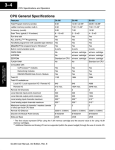
3–14
CPU Specifications and Operation
Memory Cartridge
The diagram below displays a Memory Cartridge for the DL440 or DL450. It shows
how the memory cartridge fits in the CPU and in the handheld programmer. It also
shows how to open the memory cartridge for selecting write protect (for CMOS
RAM) or for erasing the UVPROM. Details about connecting the handheld
programmer to the CPU is covered in DL405 Handheld Programmer Manual.
WARNING: Do not insert or remove a CPU memory cartridge while the power is
connected. Your program or password may be corrupted if this occurs. A corrupted
program can cause unpredictable operation which may result in a risk of injury to
personnel or damage to equipment. If the password becomes corrupted, you cannot
access the CPU.
Pull lever to
extract cartridge
Jumper pins 2 & 3
to Write Protect.
Jumper pins 1 & 2
to Write Enable.
Memory
Cartridge
Battery
CMOS Memory
Cartridge
D4-EE-2
UVPROM Memory
Cartridge
(with cover removed)
Retaining
Screws
P
R
OT
V
CPU Specifications
and Operation
CPU Battery
UVPROM Erasing Instructions
1) Remove cartridge from CPU or HPP
2) Remove cartridge retaining screw
3) Remove cover
4) Place cartridge in UV erasing lamp typical
12,000m w/cm2 lamp @ 2.5cm for 15–20 minutes
5) Replace cover
Jumper pin V to the
center pin
to Write Protect.
Jumper the center pin
to the unmarked pin
to Write Enable.
Memory Cartridge
Capacity Table
D4-RAM-1
D4-RAM-2
D4-UV-1
D4-UV-2
D4-EE-2
Program Storage Capacity
7.5K
15.5K
7.5 K
15.5K
15.5K
Cartridge Battery Type
Lithium
Lithium
None
None
None
Writing Cycle Life
N/A
N/A
1000
1000
>10,000
Write Inhibit
Internal jumper
Internal jumper
No
No
Internal jumper
Memory Clear Method
Electrical
Electrical
Ultraviolet light
Ultraviolet light
Electrical
DL405 User Manual, 3rd Edition, Rev. E