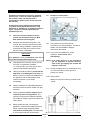
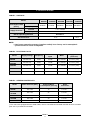
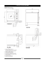
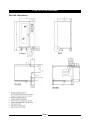
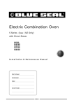
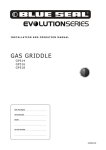
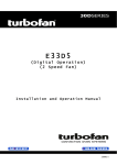
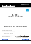
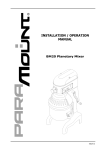
1
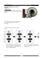
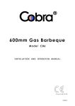
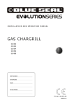
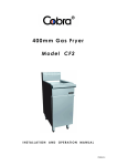
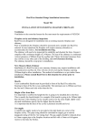
Gas Combination Oven
S series - (Aus / NZ Only)
with Direct Steam
G9CSD
G14CSD
G20CSD
G21CSD
G40CSD
Installation & Maintenance Manual
Ref; 90023620 Rev 03
234862-2
INTERNATIONAL CONTACTS
AUSTRALIA
Moffat Pty Limited
Web:
E.Mail:
Main Office:
Service:
Spares:
Customer Service:
www.moffat.com.au
[email protected]
(tel) +61 (03) 9518 3888
(fax) +61 (03 9518 3833
(tel): 1800 622 216
(tel): 1800 337 963
(tel): 1800 335 315
(fax): 1800 350 281
CANADA
Serve Canada
Web:
E.Mail:
Sales:
Service:
www.servecanada.com
[email protected]
(tel): 800 551 8795 (Toll Free)
(tel): 800 263 1455 (Toll Free)
NEW ZEALAND
Moffat Limited
Web:
E.Mail:
Main Office:
www.moffat.co.nz
[email protected]
(tel): 0800 663328
UNITED KINGDOM
Blue Seal
Web:
E.Mail:
Sales:
Spares:
Service:
www.blue-seal.co.uk
[email protected]
(tel): +44 121 327 5575
(fax): +44 121 327 9711
(tel): +44 121 322 6640
(fax): +44 121 327 9201
(tel): +44 121 322 6644
(fax): +44 121 327 6257
UNITED STATES
Moffat
Web:
Sales:
Service:
www.moffat.com
(tel): 800 551 8795 (Toll Free)
(tel): +1 336 661 1556
(fax): +1 336 661 9546
(tel): 800 858 4477 (Toll Free)
(tel): +1 336 661 1556
(fax): +1 336 661 1660
REST OF WORLD
Moffat Limited
Web:
E.Mail:
www.moffat.co.nz
[email protected]
The reproduction or copying of any part of this manual by any means whatsoever is strictly forbidden unless authorized previously in
writing by the manufacturer.
In line with policy to continually develop and improve its products, Moffat Ltd. reserves the right to change the specifications and
design without prior notice.
© Copyright Moffat Ltd. March 2011.
234862-2
CONTENTS
Page
1.
• INTRODUCTION
2
2.
• SPECIFICATIONS
4
3.
• INSTALLATION DIAGRAMS
5
4.
• SPECIAL REQUIREMENTS FOR THE INSTALLATION SITE
11
5.
• STATUTORY REQUIREMENTS AND TECHNICAL REGULATIONS
12
6.
• POSITIONING
12
7.
• ELECTRICAL CONNECTIONS AND EARTH BONDING
13
8.
• POINTS TO REMEMBER WHEN MAKING THE ELECTRICAL CONNECTION
14
9.
• WATER AND DRAIN CONNECTIONS
14
10.
• VENTS
17
11.
• GAS CONNECTION PROCEDURES
17
12.
• OPERATING AT THE RATED HEAT OUTPUT
18
13.
• COMMISSIONING AND TESTING
22
14.
• IMPORTANT INFORMATION FOR THE USER
22
15.
• MAINTENANCE
23
16.
• GAS CONVERSION AND SPECIFICATIONS
23
• NOTES
26
MODELS
G9CSD
G14CSD
G20CSD
G21CSD
G40CSD
- Gas Combination Oven,
- Gas Combination Oven,
- Gas Combination Oven,
- Gas Combination Oven,
- Gas Combination Oven,
9 of 1/1 GN Trays.
14 of 1/1 GN Trays.
20 of 1/1 or 10 of 2/1 GN Trays.
20 of 1/1 GN Trays.
40 of 1/1 or 20 of 2/1 GN Trays.
VERSIONS
S - Programmable electronics with direct access key to the programs and recipes, automatic humidity
control and lighting.
The manufacturer accepts no liability for any inaccuracies in this manual
attributable to printing or copying errors. We reserve the right to modify
our products as we deem fit, without impairing their basic features.
The reproduction or copying of any part of this manual by any means
whatsoever is strictly forbidden unless authorized previously in writing
by the manufacturer.
15.09.2008
234862-2
1
1. INTRODUCTION
We are confident that you will be delighted with your Blue Seal Combi Oven, and it will become a most
valued appliance in your commercial kitchen.
To ensure you receive the utmost benefit from your new Blue Seal appliance, there are two important
things you can do.
Firstly
Please read the instruction book carefully and follow the directions given. The time taken will be well
spent.
Secondly
If you are unsure of any aspect of the installation, instructions or performance of your appliance,
contact you BLUE SEAL dealer promptly. In many cases, a phone call could answer your questions.
WARNING:
INSTRUCTIONS TO BE FOLLOWED IN THE EVENT THE USER SMELLS GAS ARE TO BE POSTED IN A PROMINENT
LOCATION. THIS INFORMATION SHALL BE OBTAINED BY CONSULTING THE LOCAL GAS SUPPLIER.
WARNING:
GREAT CARE MUST BE TAKEN BY THE OPERATOR
TO USE THE EQUIPMENT SAFELY TO GUARD IT AGAINST
RISK OF FIRE.
•
•
THE APPLIANCE MUST NOT BE LEFT ON UNATTENDED.
IT IS RECOMMENDED THAT A REGULAR INSPECTION IS MADE BY A QUALIFIED SERVICE PERSON TO
ENSURE CORRECT AND SAFE OPERATION OF YOUR APPLIANCE IS MAINTAINED.
WARNING:
DO NOT STORE OR USE GASOLINE OR OTHER FLAMMABLE VAPOURS OR LIQUIDS IN THE VICINITY OF THIS
OR ANY OTHER APPLIANCE.
DO NOT SPRAY AEROSOLS IN THE VICINITY OF THIS APPLIANCE WHILE IT IS IN OPERATION
WARNING:
IMPROPER INSTALLATION, ADJUSTMENT, ALTERATION, SERVICE OR MAINTENANCE CAN CAUSE PROPERTY
DAMAGE, INJURY OR DEATH. READ THE INSTALLATION, OPERATING AND MAINTENANCE INSTRUCTIONS
THOROUGHLY BEFORE INSTALLING OR SERVICING THIS APPLIANCE .
C AUTIO N :
This appliance is for professional use and is only to be used by qualified people
234862-2
2
1. INTRODUCTION
Installations must be carried out by qualified
persons only. Failure to install equipment to
the relevant codes and manufacturer’s
specifications shown in this section will void
the warranty.
1.8
Components having adjustments protected
(e.g. paint sealed) by manufacturer are only
allowed to be adjusted by an authorised service
agent. They are not to be adjusted by the
installation person.
1.1
The oven must be installed, commissioned and maintained only by a Blue
Seal authorized service agent.
1.2
Carefully read the directions given in this
manual; they contain important information
on safety during installation, operation and
maintenance. Keep this manual in a safe
place for future consultation!
AM
X
E
1.9
This appliance is for professional use and is
only to be used by qualified personnel.
1.4
1.6
Packing materials must be disposed of in
conformity with local regulations. This
normally means that the different materials
are sorted according to type and collected as
urban refuse.
1.7
Before positioning and connecting the
appliance, check that the utilities (electrical
power, water and gas supplies) are as
indicated on the data plate. The data plate
is on the right-hand side, at the bottom.
The positions of the inlet and drain
connections are clearly labelled. For further
details, see the installation diagram
attached to this manual.
1.11 During installation and / or maintenance work
it is recommended you wear gloves to
protect your hands.
Having removed the packing check that the
appliance is not damaged in any way. If in
doubt, proceed no further with installation of
the appliance and contact the Blue Seal
Customer Service or your dealer
immediately.
Packing materials are potentially dangerous
and must not be left where children can play
with them.
O
NOTE: If for some reason it is not possible to
get the appliance to operate correctly,
shut off the gas supply and contact the
supplier of this unit.
This appliance must be put only to the use
for which it is specifically intended,
i.e. cooking foods; any other type of use is
improper and therefore dangerous.
1.5
E
PL
Y
NL
1.10 In the event of breakdown or faulty
operation, switch off the oven
immediately!
C AUTIO N :
1.3
Example of a data plate:-
1.12 Safety sticker
• Maximum height for inserting containers with
liquids.
234862-2
3
2. SPECIFICATIONS
TABLE 1: GAS DATA
Model
Consumption Rate
[MJ/hr]
Supply Pressure
G9CSD
Nat Gas
38 MJ/hr
LPG (Propane)
G14CSD
G20CSD
71 MJ/hr
100 MJ/hr
Nat Gas
1.13 - 5.0 kPa
LPG (Propane)
2.75 - 6.0 kPa
G21CSD
G40CSD
120 MJ/hr
200 MJ/hr
See Note 1.
Burner Operating Pressure
Gas Connection
R ½”
R ¾”
NOTE:
1. Gas burner operating pressure (regulator outlet) is ex-factory set for atmospheric
pressure and it is not to be adjusted.
TABLE 2: ELECTRICAL DATA
Supply Voltage
Frequency
Electrical Power
Input
Motor
Supply Cable
(Oil-Proof)
230-240 V ac
50 Hz
0.5 kW
1 x 0.25 kW
3 x 1mm2 (10A)
230-240 V ac
50 Hz
1.0 kW
1 x 0.55 kW
3 x 1mm2 (10A)
G20CSD
230-240 V ac
50 Hz
1.0 kW
1 x 0.55 kW
3 x 1mm2 (10A)
G21CSD
230-240 V ac
50 Hz
1.8 kW
2 x 0.55 kW
3 x 1mm2 (10A)
G40CSD
230-240 V ac
50 Hz
1.8 kW
2 x 0.55 kW
3 x 1mm2 (10A)
Model
G9CSD
G14CSD
TABLE 3: GENERAL WATER DATA
Water Pressure [kPa]
Softened Water
Consumption [max.l/h]
200 - 500
15
2 x R ¾"
(1)
200 - 500
22
2 x R ¾"
(1)
G20CSD
200 - 500
22
2 x R ¾"
(1)
G21CSD
200 - 500
30
2 x R ¾"
(1)
G40CSD
200 - 500
44
2 x R ¾"
(1)
Model
G9CSD
G14CSD
(1)
Water
Connection
The ovens are equipped with two water inlets, one for non-softened cold water and the other for hot water
(max. 50 °C) or softened cold water.
234862-2
4
3. INSTALLATION DIAGRAMS
G9CSD- Dimensions
234862-2
5
3. INSTALLATION DIAGRAMS
G14CSD - Dimensions
234862-2
6
3. INSTALLATION DIAGRAMS
G20CSD - Dimensions
234862-2
7
3. INSTALLATION DIAGRAMS
G21CSD- Dimensions
234862-2
8
3. INSTALLATION DIAGRAMS
G40CSD- Dimensions
234862-2
9
3. INSTALLATION DIAGRAMS
DISTANCES TO OBSERVE
We recommend keeping a distance of 500mm
(20”) on the right-hand side in order to carry out
maintenance work.
DO NOT INSTALL APPLIANCES WITH
A SOURCE OF HEAT ON THE RIGHTHAND SIDE OF THE OVEN.
C AUTIO N :
If the ambient temperature to the
right of the appliance is too high, the
oven will stop for safety reasons.
Minimum distance from sources of heat on
the right-hand side: 400mm (15.7”).
234862-2
10
4. SPECIAL REQUIREMENTS FOR THE INSTALLATION SITE
Installation Requirements
NOTE:
• It is most important that this appliance is installed correctly and that operation is correct before
use. Installation shall comply with local electrical, gas, health and safety requirements.
• This appliance shall be installed with sufficient ventilation to prevent the occurrence of
unacceptable concentrations of health harmful substances in the room, the appliance is installed
in.
This appliance is designed to provide years of satisfactory service, and correct installation is essential to
achieve the best performance, efficiency and trouble-free operation.
It must be installed in accordance with applicable National and Local installation gas, electrical and fire
safety codes / regulations.
AUSTRALIA:
NEW ZEALAND:
Australia / New Zealand:
- AS5601
- NZS5261
- AS / NZS3000
- AS / NZS3500
- Gas Installations.
- Gas Installation.
- Wiring Rules.
- Plumbing and Drainage Code.
Installations must be carried out by qualified persons only. Failure to install equipment to the
relevant codes and manufacturer’s specifications shown in this section will void the warranty.
Components having adjustments protected (e.g. paint sealed) by the manufacturer are only allowed
to be adjusted by an authorised service agent. They are not to be adjusted by the installation
person.
The manufacturer accepts no liability for any damage or malfunctioning of the appliance
attributable to the absence or inadequacy of earthing systems, to the incorrect arrangement or
installation of auxiliary systems, also to incorrectly made connections or to non-compliance of the
building's electrical system with current regulations.
4.1
The room where the oven is to be fitted has
to be well ventilated with all the openings
required for rooms with gas installations
(Refer to specific regulations).
NOTE: It is important that adequately sized
piping runs directly to the connection
joint on the appliance, with as few tees
and elbows as possible to give
maximum supply volume.
4.2
Current accident prevention guidelines;
4.5
4.3
The oven needs a water supply,
incorporating a softener with suitable flow
and pressure specifications (see Section 2
“Specifications” and Section 9 “Water
and Drain Connections”). A shutoff valve
must be installed on each of the water supply
pipelines to the appliance.
4.4
The room must have a water drain in a good
position for the oven to be installed, its
specifications are given under Section 8
“Water and Drain Connections” in this
manual.
The gas supply plumbing must be installed
in accordance with current regulations,
adopting pipe sections and pressures
suitable for the appliance (see Section 2
“Specifications” and Section 11 “Gas
Connections Procedures”). A fast acting
shutoff valve must be installed on the gas
inlet line to the appliance. It is absolutely
essential that this valve should be specified
to current standards and type test approved.
4.6
The electrical isolating switch and the water
and gas shutoff valves must all be located
near to the appliance, within easy reach for
the user.
234862-2
11
5. STATUTORY REQUIREMENTS, TECHNICAL REGULATIONS AND DIRECTIVES
Throughout installation it is vital to observe the
following requirements:
5.1 Any health and hygiene standards applicable
to kitchens and eating places;
5.2 Local and/or territorial building regulations
and fire prevention standards.
5.3 Current accident prevention guidelines;
5.4
5.5
The regulations of the electrical power
supply company or agency;
Any other local regulations.
6. POSITIONING
6.1
To position the appliances, it is
recommended to use the mount offered by
the manufacturer; should you want to do
things differently, it is necessary to take
account of the weight of the appliance.
6.2
Before manoeuvring the oven into the
selected position, attach the water inlet
hoses and waste pipe to the relative
connection points (See Section 9 “Water
and Drain Connections”).
6.3
The distances from other appliances or from
adjacent walls that must be left to allow
access for servicing operations will be found
on the installation diagram for the oven to
connect. In the event of the oven being
installed directly against an inflammable wall,
suitable heat insulation must be
provided. Current fire regulations should be
meticulously observed and respected. Do
not obstruct the openings and slots in the
casing as they disperse the heat in the
electric component compartment. Keep
strictly to the installation diagrams.
6.4
Once the appliance is installed, the
electrical power cable must be protected,
and never stretched or tugged.
6.5
The appliance must be level: any
difference in level or sloping of the supporting surface should be eliminated.
Differences in level or sloping negatively
affect oven operation.
6.6
Remove all packing materials and peel away
the protective plastic film from all external
surfaces of the oven.
6.7
234862-2
12
For free-standing models, the appliance
needs to be levelled: small differences in
level of the supporting surface can be
eliminated with the adjustable feet (by
screwing or unscrewing them).
A significantly uneven or sloping stance can
affect the operation of the oven adversely.
For models equipped with a pan trolley, it is
necessary to pay special attention when
levelling.
6. POSITIONING
6.8
Lining up the pan trolleys G20CSD and
G21CSD. If the floor is not level, a remedy
must be found using an access ramp with a
maximum gradient of 4° (not included in the
supply). If there is an outlet grate in front of
the appliance, it is necessary to fit runners in
the pan trolley entry area.
7. ELECTRICAL CONNECTIONS AND EARTH BONDING
NOTE: All electrical connection must only be
carried out by a qualified electrical
service person.
7.1
7.2
7.3
As this oven is supplied without a power
cable and plug, the cable and other
hardware needed to make the connection to
the electrical power supply must be provided
by the installer. The cable must satisfy the
requirements indicated in Table 1
'Electrical Data'.
The oven must be connected to the power
supply by way of a multiple pole main
isolating switch ensuring a gap between
open contacts of at least 3mm on each pole.
The cable must be fed in from beneath the
clamp. The individual wires are then
fastened to the corresponding terminals of
the terminal board. The earth wire must be
longer than the other wires, so that in the
event of the cable being jerked or the clamp
broken, the live wires will disconnect first.
Check the efficiency of the isolating switch
The oven must be kept in an equipotential
system. This connection is made by wiring a
conductor of nominal cross section 10mm2 to
the corresponding terminal at the back of the
oven, which is marked with the
internationally recognized symbol. All
appliances in the room are bonded in this
way and connected to the earth system of
the building.
To gain access to the AC mains connection
terminal board, the right hand panel of the
casing must be removed by undoing the
fixing screws (all models).
7.4
234862-2
13
The electrical safety of this appliance can be
guaranteed only when it is connected
correctly to an efficient earth system, in
compliance with current standards.
8. POINTS TO REMEMBER WHEN MAKING THE ELECTRICAL CONNECTION
8.1
As all ovens of the series are fitted with an
alternating fan motor (clockwise and anticlockwise rotation), there is no need for the
fan to rotate in any particular direction. Simply verify, when commissioning the
appliance, that the fan is balanced and
rotates freely.
8.3
This problem is indicated by:On gas models mechanical version by
the burner ignition reset button, which is
lit up.
On gas models electronic version via
the electronic card.
8.4
Check also that the neutral registers zero
potential when tested. If not, the fault
already described in Item 8.3 of this section
will occur. In this eventuality, consult the
installer of the building's electrical system.
C AUTIO N :
The G21CSD and G40CSD models are
equipped with two motors.
8.2
When making the electrical connection, care
is needed to ensure that the neutral pin of
the terminal block corresponds to the neutral
wire of the supply line. If this connection is
not made correctly, the burners will not
operate correctly.
9. WATER AND DRAIN CONNECTIONS
Australia / New Zealand only:
Water installation must be done in compliance with AS/NZS 3500 Plumbing and
Drainage Code.
9.2
The water connection is R 3/4”.
Australia only:
Double Check Valve supplied with this appliance must be installed in the water supply
line to this appliance to provide total backflow prevention
required by Plumbing Code of Australia.
This valve must be installed on upstream of
any water filtering or conditioning device installed in association with this appliance, i.e.
before the
water supply line separation into the separate inlet water connections (A) and (B) of
this appliance.
9.1
WATER CONNECTIONS
The water supplied must be either cold and
softened or hot (max 50 °C), as described
below.
The hose for connection to the water supply
must be provided by the installer. A shutoff
valve must be installed in the line between
the oven and the mains supply.
9.3
WATER SPECIFICATIONS
The characteristics of the water must be
within the limits given below, in order to
prevent corrosion, which is extremely
damaging for the appliance, due to supplying
water that is too softened or too aggressive,
and scaling in the oven and in the water
system due to water that is too hard.
Hardness: between 3° and 6° TH.
PH:
greater than 7.5.
Chlorides: less than 30 ppm.
WATER PRESSURE
The pressure of the water in the network
must be between 200 and 500 kPa, as
already stated under the Section 2
'Specifications'. If the supply pressure is
higher than this, a pressure reduction valve
must be installed between the oven and the
These values are important for ensuring that
the water used by the appliance is suitably
treated.
234862-2
14
9. WATER AND DRAIN CONNECTIONS
9.4
WATER CONNECTIONS FOR
CONDENSING STEAM
The water used for condensing steam need
not be softened, but must be cold. The
water connection is R 3/4. The hose for
connecting to the water supply must be
provided by the installer. A shutoff valve
must be installed in the line between the
oven and the mains supply.
9.5
DRAINING
The water is drained off by gravity through a
heat-resistant pipe DN 50 (not flexible),
maximum length 2m, installed at an angle of
no less than 4°. Mean temperature of the
drain water: 65°C.
For the range with the drain as per Fig 1, it
is possible to make a direct connection with
an air trap, without fitting a drain cup, as the
drainage manifold system has an internal air
drop (Fig. 2). With a drain on the floor
without an air trap, it is necessary to have an
outlet clearance of 2cm (Fig. 3).
For the remaining models, it is imperative to fit a
tundish to ensure a minimum air drop of 25mm.
between the appliance's plastic drain elbow and
drain line. A direct connection is not
permissible.
C AUTIO N :
The drain line must be outside the
perimeter
of
the
oven.
It
is
prohibited
to
reduce
the
drain
diameter.
234862-2
15
9. WATER AND DRAIN CONNECTIONS
9.6
FITTING THE HAND SHOWER
NOTE:
To fit the shower attachment, the oven RH
side panel must be removed. Do NOT attempt to fit the hand shower attachment
without removing the side panel as electrical
equipment behind the panel can get
damaged and there is potential for causing
electric shock. Ensure electrical power is
disconnected before commencing.
5. Ensure that the water
supply is turned off at
the mains shut-off
valve.
6. Connect up the hose
connection from the
shower head to the ‘T’
connection at the rear of
the oven.
The oven is supplied with a hand shower
attachment which must be fitted to the oven as part
of the installation process.
NOTE:
Ensure that the supplied sealing washers are
fitted between the ‘Tee’, Hose and Hand
Shower.
To fit the hand shower attachment, the right hand
side panel of the oven must be removed to drill and
attach the hand shower mounting bracket.
To fit the hand shower attachment, carry out the
following operation:1. Remove the 3
screws securing the
right hand side
panel (as viewed
from front of oven).
7. Fit the shower head to
the shower head
mounting bracket.
Oven R/H
Side Panel
8. Turn ‘On’ the water
supply and check for
leaks.
9. Carry out a functional
check of the shower
head.
Remove 3 Screws
60 mm
2. Drill a 5.5 mm hole
in the top left hand
corner of the side
panel as shown on
the diagram below.
Oven R/H
Side Panel
60 mm
Connect Shower Head
Hose Connection Here.
3. Secure the shower head mounting bracket to
the side panel with the bolt, nut and washers
supplied.
Mounting
Bracket
Reverse Side
of Panel
4. Refit the side panel to the oven and secure with
3 screws.
234862-2
16
Mounting
Bracket
Shower
Head
10. VENTS
10.1 Under no circumstances must vents A
and B be shut, blocked or ducted into
other pipes.
A - Vent to extract vapours from the oven.
B - Safety vent.
11. GAS CONNECTION PROCEDURES
NOTE: Do not obstruct or block the
appliances flue.
Never directly
connect a ventilation system to the
appliance flue outlet.
Installation Requirements
NOTE: This appliance shall be installed with
sufficient ventilation to prevent the
occurrence
of
unacceptable
concentrations of health harmful
substances in the room, the appliance
is installed in.
WARNING:
FLUE GASES MAY REACH TEMPERATURES OF 400°C.
FLUE
11.1 GAS CONNECTION
GASES
MUST
NEVER
BE
DUCTED
AWAY
UTILIZING AN EXTRACTION SYSTEM.
NOTE: All gas fitting must only be carried
out by a qualified gas service person.
CLEAR THE GAS SUPPLY SYSTEM OF ANY MACHINING DEBRIS BEFORE CONNECTING UP THE OVEN.
The section of the gas supply pipe must be
chosen according to the type of gas and the
consumption of the appliance to be
connected. The system must be designed
and installed in accordance with current
regulations.
11.2 LEAK TEST
WARNING:
DO
NOT USE A NAKED FLAME TO CHECK FOR GAS
LEAKAGES.
The gas connection on the oven is either
R 1/2” or R 3/4”, and this section must
never be reduced.
All connections between the mains and the
appliance must be tested for leakage. The
recommended method is to use a proprietary
leak detection spray; alternatively, a noncorrosive foamy liquid of any general
description can simply be brushed onto the
fittings: whichever method is used, no
bubbles should appear.
A fast acting shutoff valve must be installed
on the gas inlet line to the oven. The valve
must be type test approved in accordance
with current regulations.
A suitable joining compound which resists
the breakdown action of LPG must be used
on every gas line connection, unless
compression fittings are used.
The manufacturer accepts no liability for any damage or malfunctioning of the appliance
attributable to the absence or inadequacy of earthing systems, to the incorrect arrangement or
installation of auxiliary systems, also to incorrectly made connections or to non-compliance of the
building's electrical system with current regulations.
234862-2
17
12. OPERATING AT THE RATED HEAT OUTPUT
12.4 MEASURING THE SUPPLY PRESSURE
The inlet pressure is measured using a
manometer connected to the supply
pressure test point (B) of the gas control
valve. To gain access to the valve, remove
the right-hand side casing panel. Before
connecting the manometer, loosen the screw
sealing the supply pressure test point (B).
Now measure the pressure with the burner in
operation. The value shown on the
manometer must come within the limits given
in Section 2 ‘Specifications’, ‘Table 1: Gas
Data’.
After checking, carefully close the supply
pressure test point (Screw B). The sealed
screws on the valves must never be
tampered with under any circumstances.
WARNING:
THE GAS SYSTEM COMPONENTS ARE FITTED FOR A
6.0 KPA.
HIGHER SUPPLY PRESSURES ARE NOT
PERMISSIBLE.
MAXIMUM PRESSURE OF
12.1 During final testing in the factory, all
appliances are fitted for the type of gas
shown on the sticker next to the rating plate.
Should the appliance fitting not correspond
to the gas type available on location, the
appliance must be converted to adapt to the
type of gas available. Refer to the Gas
Conversion Section.
12.2 Commissioning of the appliance to operate
at the rated heat output is dependent on the
inlet pressure, calorific value of the gas and
the correct amount of primary air.
12.3 The inlet pressure required for the appliance
to operate with the various types of gas
typically available will be within the limits
indicated in Section 2 'Specifications',
'Table 1: Gas Data'.
The appliance must not be commissioned
if inlet pressure values are outside these
limits. If pressures differ from those
indicated in Table 1, the gas supply
company or agency should be contacted, or
alternatively the contractor by which the
system was installed in the building.
Gas Mix Rate
B - Supply Pressure
Test Point
NOTE: Mix screw and burner operating
pressure are ex-factory fixed and
further adjustment is not provided
nor required.
If for some reason it is not possible to
get
the
appliance
to
operate
correctly, shut off the gas supply and
contact the supplier of this unit.
234862-2
18
12. OPERATING AT THE RATED HEAT OUTPUT
CHECKING NOMINAL HEAT CAPACITY
S VERSION
- Chamber Burner
Check the depth of the screw “A” in accordance
with table 5 of the “Tecnical gas data” booklet, using
a gauge.
Check that the burner fan speed, corresponds to
the data given in table 5 of the “Technical gas
data” booklet.
To enter the management screen of the burner to
Check :
With the appliance live and display off, press
button 1,the display 2 shows [USb], turn
knob 3 until [rEL] is displayed, press the
knob to confirm the selection
Turn knob until [123] (access password for
parameter modification) and confirm by
pressing knob 3
234862-2
19
12. OPERATING AT THE RATED HEAT OUTPUT
1
2
3
4
5
Turn knob 5 until [br1] on display 7 and
confirm by pressing knob 3.
Display 2 shows parameter [151] IGN ignition speed and display 4 shows the ignition
speed value (example [110]).
To modify the value press knob 5, turn to
knob 5 to set the new value and confirm by
pressing knob 5.
Turning knob 3 takes us to display 2 and
visualisation of parameter [152] minimum
speed, and display 4 shows the minimum
speed value (example [136]).
Turning knob 3 again takes us to display 2
and visualisation of parameter [153] maximum speed, and display 4 shows the
maximum speed value (example [173]).
Press button 1 to select another burner by
turning knob 5.
Proceed in the same way to check the values of the other burners if present
(example [br2]).
234862-2
20
12. OPERATING AT THE RATED HEAT OUTPUT
1
6
2
3
4
5
Then, to test the correct functioning of the
burners, exit the screen by pressing 1.
During testing, it is possible to manually
block the sequence by pressing button 1; this
way, the burner blocks in the desired phase
(ex. IGN ignition) allowing the technician to
carry out other verifications in this phase.
To test chamber burner [br1], turn scroller 5
until [br1] on display 2, and then start-up the
cycle with the 6 “START/STOP”button.
When a phase is blocked, the point indicating
phase 1, 2 or 3 flashes.
The burner will go in pre-ventilation to then
pass on to the set IGN ignition. The first IGN
ignition stage is indicated on display 4, by the
first point under the speed value.
To restart the sequence, always press button 1.
NOTE: in case of maximum speed, the cycle block becomes pointless since the oven
is already working normally; it is possible to
shift to minimum phase by pressing key 1.
Then, the minimum and maximum speed
stages, indicated respectively in the second
and third points, will automatically activate.
To carry out the tests with the door open,
once the cycle is started, press the “CLIMA”
button; this function is useful during combustion analysis and for functioning tests of
the prolonged burner without reaching the
temperature previously set in the chamber
The correct burner functioning is highlighted
by the increase of the temperature in the
cooking compartment.
Once reached a speed stage, press button 1
to shift to the previous stage.
To deactivate burner functioning, press button 6 “START/STOP” again.
To exit the cycle press button 1.
NOTE: To check/adjust the boiler burner, activate
the Boiler Burner section (example [br2]) as operated for cooking compartment burner heating
234862-2
21
13. COMMISSIONING AND TESTING
13.3 You should moreover check that the silicone
joints and sleeves of the water circuit (oven
vent, oven outlet, drip tray) do not leak.
13.1 Check the appliance and the entire
installation as soon as connection has been
completed.
13.4 Carefully refit the right-hand side that was
removed for the above work.
Check in particular:
• That there are no traces of the protective
film on the outside walls and that the oven
is empty;
• All vents are clear;
• The connections are made as required and
instructed in this handbook;
• All the safety requirements of the current
standards, laws and directives are met;
• There is no leakage from the gas and
water connections;
• Water drainage and flue gas extraction are
clear.
13.5 For an additional check that the appliance is
operating correctly, carry out a volumetric
measurement of the quality of gas
consumed. The meter will show how much
gas has been consumed over a given
period of time, and this value can be
checked against the values given in
Section 2 'Specifications', Table 1 “Gas
Data".
13.6 The test report must be completed in full and
submitted to the customer, who should then
sign in acceptance. With effect from this
moment, the appliance is covered by the
manufacturer’s warranty.
13.2 Now proceed to light the oven as directed in
the 'User Operating Manual', checking the
smooth ignition of the burner.
14. IMPORTANT INFORMATION FOR THE USER
14.4 Keep the installation manual and the wiring
diagram for future reference. Explain to the
user that the user manual supplied with the
oven must be kept near the oven in a place
where it can be seen. It is good policy to
make a note, in the user manual, of the
name and contact numbers of the selected
Service Agent.
14.1 With the user manual to hand, show the user
the functions, safety devices, appropriate
use and, above all, the time intervals for
servicing the oven.
Maintenance operations include cleaning the
burners, inspecting the combustion chamber
and cleaning the various ducts and pipes,
and should be carried out at least once a
year.
Customers are recommended to sign a
service agreement.
14.5 Explain to the user that certain faults in
operation are often due to simple errors or
oversights such as failure to switch on or
connect utilities. Accordingly, kitchen staff
should be trained in such a way that they can
use the appliance confidently and
understand how it operates. Faults of a
recurring or persistent nature must be
investigated by a Blue Seal authorized
Service Agent.
14.2 Ensure the user is fully aware that such
repair and / or maintenance operations as
may become necessary over time must be
carried out only by a Blue Seal authorized
service agent.
14.3 Explain clearly to the user that in the event of
breakdown or faulty operation, all connected
utilities (water, electricity and gas) should be
shut off immediately.
14.6 Explain clearly that any alterations to the
room or changes in ventilation may affect the
operation of gas-fired appliances. In these
cases, it is advisable to have the oven
functions checked over.
234862-2
22
15 MAINTENANCE
15.1 MAINTENANCE PROCEDURE
Every 6 months the burner air supply inlet located
behind the service panel should be inspected and
cleared of any build up of material to ensure an
un-obstructed air supply to the burners.
1. Carefully pull out the burner air supply pipe
from the air inlet elbow (this is a push fit).
2. Clean out the pipe ensuring that there are no
blockages.
3. Refit the burner air supply inlet to the air inlet
elbow.
Air Inlet Elbow
Burner Air
Supply Inlet
Fig 1
16. GAS CONVERSION AND SPECIFICATIONS
16.1 GAS CONVERSION PROCEDURE
1. Turn off the electrical and gas supplies to the
appliance at the mains supply.
2. Remove the right hand side panel from the
appliance by removing the 2 screws from the
lower edge of the panel and remove the side
panel.
3. Carefully pull off the inlet elbow from the end of
the blower. (Refer to Fig 2).
C AUTIO N :
Ensure that the Unit is isolated from
the gas supply before commencing
servicing.
NOTE:
• These conversions should only be carried
out by qualified persons. All connections
must be checked for leaks before
re-commissioning the appliance.
• For all relevant gas specifications refer to
the table at the end of this section.
Air Inlet
Elbow
Gas appliances are commissioned as standard to
run on Natural Gas. Requests for commissioning
for different types of gas (e.g. LPG) must be made
at the time of ordering, or use the conversion kit
included with the appliance.
It is important that the correct gas orifice disc is
fitted for the gas type the unit is going to be used
on. Refer to the table at the rear of this section for
gas specification details.
This disc, which acts as a gas duct diameter
reducer, must be fitted at the gas valve outlet, as
shown overleaf.
Fig 2
4. Unscrew and remove the 3 screws at the rear of
the gas valve, ensuring that the allen key is no
longer than 100mm (for access purposes).
Gas Valve
Mounting Screws
234862-2
23
Fig 3
17. GAS CONVERSION AND SPECIFICATIONS
5. Remove the black rubber gasket fitted to the
gas valve outlet (Refer to Fig 4) and replace the
brass disc inside the gasket with the correct
orifice size specified in the 'Gas Specifications
Data' table at the rear of this section.
Disc
6. Check that the central orifice is free from burrs
that could cause turbulence when the gas
passes through it.
Rubber
Gasket
Fig 4
7. Position the gasket / disc assembly into the gas
valve outlet, making sure that it fits snugly
around the full perimeter of the valve outlet.
(Refer to Fig 4).
8. Refit the gas valve to the rear of the blower and
secure in place with the 3 screws. (Refer to Fig
3 on previous page).
NOTE: Ensure that all wiring connections to
the gas valve and ignition module
remain intact, especially the burner
flame sensor wire connection.
Ensure that the Burner
Flame Sensor Wire is not
Damaged or Broken
17.2 GAS MIXING SCREW
Gas Mix Screw is ex-factory set at 10mm depth
and it is not to be adjusted.
17.3 BURNER BLOWER SPEED ADJUSTMENT
Adjust the Burner Blower Speed as shown in
Section 12.5 'Checking Nominal Gas Input
Rate', sub section 'Burner Blower Speed'.
234862-2
24
Fig 5
17. GAS CONVERSION AND SPECIFICATIONS
GAS SPECIFICATIONS
Model
Consumption Rate
[MJ/hr]
Gas Flow Orifice
[mm]
Mix Screw [mm]
(See Note 1)
G9CSD
G14CSD
G20CSD
G21CSD
G40CSD
38
71
100
120
200
Nat Gas
Ø 4.40
Ø 5.40
Ø 5.40
Ø 5.40
Ø 5.40
LPG (Propane)
Ø 2.90
Ø 3.90
Ø 4.10
Ø 3.90
Ø 4.10
Butane
Ø 2.80
Ø 3.70
Ø 3.80
Ø 3.70
Ø 3.80
Nat Gas
10
10
10
10
10
LPG (Propane)
Butane
10
10
10
10
10
Ign
110
110
110
110
110
Min
135
140
140
140
140
Max
175
175
190
175
190
Ign
110
110
110
110
110
Min
135
140
140
140
140
Max
185
175
185
175
185
Nat Gas
LPG (Propane)
Nat Gas
Burner Fan Speed
[Hz]
LPG
(Propane)
Butane
Supply Pressure
Nat Gas
1.13 - 5.0 kPa
LPG
2.75 - 6.0 kPa
See Note 2.
Burner Operating Pressure
Gas Connection
NOTE:
1.
2.
R ½”
R ¾”
Mix screw is ex-factory set to 10 mm (± 1.0) depth and it is not to be adjusted.
Gas burner operating pressure (regulator outlet) is ex-factory set for atmospheric
pressure and it is not to be adjusted.
234862-2
25
NOTES
Check the combustion, CO (ppm) and CO2 (%)values, with an appropriate instrument:
Start the oven working, 180°C convection mode, open the door and short the micro-door with a
magnet fixed with tape, the oven restarts and wait for approximately 5 minutes. Position the flue
gas collection probe in the flue gas outlet pipe (chamber and boiler).
The CO2 must b
234862-2
26