1
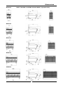
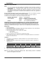
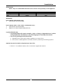
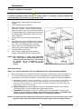
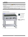
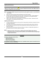
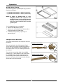
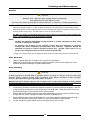
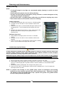
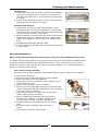
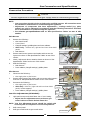
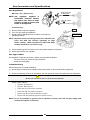
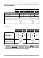
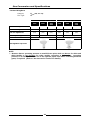
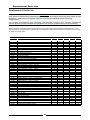
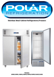
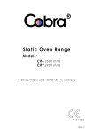
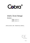
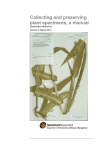
` INSTALLATION AND OPERATION MANUAL GAS CHARGRILL G592 G593 G594 G596 G598 For use in GB, IE & DK 228593-24 MANUFACTURED BY Moffat Limited Rolleston 7675 New Zealand INTERNATIONAL CONTACTS AUSTRALIA Moffat Pty Limited Web: E.Mail: Main Office: Service: Spares: Customer Service: www.moffat.com.au [email protected] (tel) +61 (03) 9518 3888 (fax) +61 (03) 9518 3838 (tel): 1800 622 216 (tel): 1800 337 963 (tel): 1800 335 315 (fax): 1800 350 281 CANADA Serve Canada Web: E.Mail: Sales: Service: www.servecanada.com [email protected] (tel): 800 551 8795 (Toll Free) (tel): 800 263 1455 (Toll Free) NEW ZEALAND Moffat Limited Web: E.Mail: Main Office: www.moffat.co.nz [email protected] (tel): 0800 663328 UNITED KINGDOM Blue Seal Web: E.Mail: Sales: Spares: Service: www.blue-seal.co.uk [email protected] (tel): +44 121 327 5575 (fax): +44 121 327 9711 (tel): +44 121 322 6640 (fax): +44 121 327 9201 (tel): +44 121 322 6644 (fax): +44 121 327 6257 UNITED STATES Moffat Web: Sales: Service: www.moffat.com (tel): 800 551 8795 (Toll Free) (tel): +1 336 661 1556 (fax): +1 336 661 9546 (tel): 800 858 4477 (Toll Free) (tel): +1 336 661 1556 (fax): +1 336 661 1660 REST OF WORLD Moffat Limited Web: E.Mail: www.moffat.co.nz [email protected] The reproduction or copying of any part of this manual by any means whatsoever is strictly forbidden unless authorized previously in writing by the manufacturer. In line with policy to continually develop and improve its products, Moffat Ltd. reserves the right to change the specifications and design without prior notice. © Copyright Moffat Ltd. December 2014. Contents List G592-B G594-[2] G594-[2] G596-[2] G598-[2] NOTE: Gas Chargrill, 300mm wide - Bench Model. Gas Chargrill, 450mm wide. Gas Chargrill, 600mm wide. Gas Chargrill, 900mm wide. Gas Chargrill, 1200mm wide. [2]: LS B - On Leg Stand. - Bench Models. Introduction .............................................................................................. 2 Specification .............................................................................................. 3 Model Numbers Covered in this Specification Gas Supply Requirements Dimensions ................................................................................................ 5 Installation ................................................................................................ 8 Installation Requirements Unpacking Location Clearances Assembly Fitting Leg Stand to Chargrill Gas Connection Commissioning Operation ................................................................................................. 12 Operation Guide Description of Controls Lighting Pilot Burner Lighting Main Burner Griddle Plate Fitting Chargrill Grate Reversal Cleaning and Maintenance ...................................................................... 15 General Daily Cleaning Weekly Cleaning Periodic Maintenance Fault Finding ............................................................................................ 18 Gas Conversion and Specifications ......................................................... 19 Conversion Procedure Gas Specifications Replacement Parts List ........................................................................... 24 Introduction We are confident that you will be delighted with your BLUE SEAL CHARGRILL, and it will become a most valued appliance in your commercial kitchen. To ensure you receive the utmost benefit from your new Blue Seal CHARGRILL, there are two important things you can do. Firstly: Please read the instruction book carefully and follow the directions given. The time taken will be well spent. Secondly: If you are unsure of any aspect of the installation, instructions or performance of your appliance, contact your BLUE SEAL dealer promptly. In many cases a phone call could answer your question. CE Only: These instructions are only valid if the country code appears on appliance. If code does not appear on appliance, refer to supplier of this appliance to obtain technical instructions for adapting appliance to conditions for use in that country. Warning IMPROPER INSTALLATION, ADJUSTMENT, ALTERATION, SERVICE OR MAINTENANCE CAN CAUSE PROPERTY DAMAGE, INJURY OR DEATH. READ THE INSTALLATION, OPERATING AND MAINTENANCE INSTRUCTIONS THOROUGHLY BEFORE INSTALLING OR SERVICING THIS APPLIANCE. Warning INSTRUCTIONS TO BE FOLLOWED IN THE EVENT THE USER SMELLS GAS ARE TO BE POSTED IN A PROMINENT LOCATION. THIS INFORMATION SHALL BE OBTAINED BY CONSULTING THE LOCAL GAS SUPPLIER. Warning GREAT CARE MUST BE TAKEN BY THE OPERATOR TO USE THE EQUIPMENT SAFELY TO GUARD IT AGAINST RISK OF FIRE. THE APPLIANCE MUST NOT BE LEFT ON UNATTENDED. IT IS RECOMMENDED THAT A REGULAR INSPECTION IS MADE BY A COMPETENT SERVICE PERSON TO ENSURE CORRECT AND SAFE OPERATION OF YOUR APPLIANCE IS MAINTAINED. DO NOT STORE OR USE GASOLINE OR OTHER FLAMMABLE VAPOURS OR LIQUIDS IN THE VICINITY OF THIS OR ANY OTHER APPLIANCE. DO NOT SPRAY AEROSOLS IN THE VICINITY OF THIS APPLIANCE WHILE IT IS IN OPERATION. Caution This appliance is for professional use and is only to be used by qualified persons. Only authorised service persons are to carry out installation, servicing or gas conversion operations. Components having adjustments protected (e.g. paint sealed) manufacturer should not be adjusted by the user / operator. DO NOT operate the appliance without the legs supplied fitted. 2 by the Specifications Model Numbers Covered in this Specification G592-B G593-[2] G594-[2] G596-[2] G598-[2] NOTE: Gas Chargrill, 300mm wide - Bench Model. Gas Chargrill, 450mm wide. Gas Chargrill, 600mm wide. Gas Chargrill, 900mm wide. Gas Chargrill, 1200mm wide. [2]: LS B - On Leg Stand. - Bench Models. Gas Supply Requirements - Australia Natural Gas G592 Input Rating (N.H.G.C.) Supply Pressure Burner Operating Pressure Gas Connection G593 G594 LP Gas (Propane) G596 G598 G592 G593 G594 G596 G598 33.0 MJ/hr 48.0 MJ/hr 66.0 MJ/hr 100.0 MJ/hr 133 MJ/hr 33.0 MJ/hr 48.0 MJ/hr 66.0 MJ/hr 100.0 MJ/hr 133 MJ/hr 1.13 - 3.40 kPa 1.0 kPa 2.75 - 4.50 kPa 0.95 kPa (*) 1 2.5 kPa 3 /2” BSP Male 2.6 kPa (*) 1 /4” BSP Male 3 /2” BSP Male /4” BSP Male - New Zealand Natural Gas G592 Input Rating (N.H.G.C.) Supply Pressure Burner Operating Pressure Gas Connection G593 G594 LP Gas G596 G598 G592 G593 G594 G596 G598 33.0 MJ/hr 48.0 MJ/hr 66.0 MJ/hr 100.0 MJ/hr 133 MJ/hr 34.5 MJ/hr 50.4 MJ/hr 69.1 MJ/hr 103.6 MJ/hr 138.2MJ/hr 1.13 - 3.40 kPa 1.0 kPa 2.75 - 4.50 kPa 0.95 kPa (*) 1 2.5 kPa 3 /2” BSP Male 2.6 kPa (*) 1 /4” BSP Male 3 /2” BSP Male /4” BSP Male - United Kingdom II2H3P (20, 30 / 37). A1. Category: Flue Type: Natural Gas (G20) Nominal Heat Input (nett) Reduced Gas Rate (nett) Nominal G593 G594 G596 G598 G592 G593 G594 G596 G598 8.8 kW 13.0 kW 18.0 kW 27.0 kW 36.0 kW 8.8 kW 13.0 kW 18.0 kW 27.0 kW 36.0 kW 3.5 kW 4.2 kW 6.0 kW 9.0 kW 18.0 kW 3.81 m3/ hr 1.27 m3/ hr 3.7 kW 0.68 kg/ hr 0.29 kg/ hr 4.3 kW 6.4 kW 9.6 kW 12.8 kW 3 3 3 3 0.93 m /hr 1.38 m /hr 1.90 m /hr 2.86 m /hr Reduced 0.37 m3/hr 0.40 m3/hr 0.63 m3/hr 0.95 m3/hr Supply Pressure Burner Operating Pressure Gas Connection Propane (G31) G592 20 mbar 10.6 mbar 1 /2” BSP Male 1.01 kg/hr 1.40 kg/hr 2.10 kg/hr 2.80 kg/hr 0.33 kg/hr 0.50 kg/hr 0.75 kg/hr 0.99 kg/hr 30 / 37 mbar 10 mbar (*) 25 mbar 1 /2” BSP Male ¾” BSP Male 26 mbar (*) ¾” BSP Male (*) - Measure burner operating pressure at manifold test point with one burner for G592 and G593 Models or two burners for other models, operating at full setting. Operating pressure is ex-factory set and is not to be adjusted, apart from when converting between gases, if required. (Refer to ‘Gas Conversion’ section for details). 3 Specifications - All Other Markets Natural Gas G592 Input Rating (N.H.G.C.) Supply Pressure Burner Operating Pressure Gas Connection G593 G594 G596 Town Gas G598 G592 G593 1.13 - 3.40 kPa 1.0 kPa G596 G598 0.75 - 1.50kPa 0.95 kPa (*) 1 0.63kPa (**) 3 /2” BSP Male 1 /4” BSP Male 3 /2” BSP Male /4” BSP Male LP Gas (Propane) G592 Input Rating (N.H.G.C.) Supply Pressure Burner Operating Pressure Gas Connection G594 33.0 MJ/hr 48.0 MJ/hr 66.0 MJ/hr 100.0 MJ/hr 133 MJ/hr 33.0 MJ/hr 48.0 MJ/hr 66.0 MJ/hr 100.0 MJ/hr 133 MJ/hr G593 G594 G596 Butane G598 G592 G593 G594 G596 G598 33.0 MJ/hr 48.0 MJ/hr 66.0 MJ/hr 100.0 MJ/hr 133 MJ/hr 33.0 MJ/hr 48.0 MJ/hr 66.0 MJ/hr 100.0 MJ/hr 133 MJ/hr 2.75 - 4.50 kPa 2.5 kPa 1 /2” BSP Male 2.75 - 4.50 kPa 2.6 kPa (*) 3 /4” BSP Male 2.5 kPa 1 /2” BSP Male 2.6 kPa (*) 3 /4” BSP Male NOTE: (*) Measure burner operating pressure at manifold test point with one burner for G592 and G593 Models or two burners for other models, operating at full setting. NAT, LPG & Butane Only - Operating pressure is ex-factory set and is not to be adjusted, unless when converting between gases, if required. (**) TOWN GAS Only - Adjust burner operating pressure using adjustable gas regulator supplied. Refer to ‘Gas Conversion and Specifications' section in this manual for further details. 4 Dimensions G592-B NOTE: The G592 is available in Bench Model (- B) Option Only. G593-B G594-B G596-B G598-B 5 Dimensions G593-LS G594-LS 6 Specifications G596-LS G598-LS R R = Rating Plate Location for all options. 7 Installation Installation Requirements NOTE: It is most important that this appliance is installed correctly and that operation is correct before use. Installation shall comply with local, gas, health and safety requirements. This appliance shall be installed with sufficient ventilation to prevent occurrence of unacceptable concentrations of health harmful substances in the room, appliance is installed in. Blue Seal chargrills are designed to provide years of satisfactory service, and correct installation is essential to achieve the best performance, efficiency and trouble-free operation. This appliance must be installed in accordance with National installation codes and in addition, in accordance with relevant National / Local codes covering gas and fire safety. Australia / New Zealand: United Kingdom: - Ireland: AS5601.1 - Gas Installations. Gas Safety (Installation & Use) Regulations 1998. BS6173 - Installation of Catering Appliances. BS5440 - 1 & 2 Installation Flueing & Ventilation. IS 820 - Non - Domestic Gas Installations. Installations must be carried out by qualified persons only. Failure to install equipment to the relevant codes and manufacturer’s specifications shown in this section will void the warranty. Components having adjustments protected (e.g. paint sealed) by manufacturer are only to be adjusted by an authorised service agent. They are not to be adjusted by the installation person. Unpacking Remove all packaging. Check equipment and parts for damage. Report any damage immediately to carrier and distributor. Remove protective plastic coating from side panels. Check the following parts have been supplied with chargrill: 1 x Gas Regulator. 1 x Gas Type Conversion Kit. Report any deficiencies to the distributor who supplied the chargrill. Check available gas supply is correct to as shown on the rating plate attached to the underside of R/H side, front hob lower trim. Location 1. 2. This appliance must be installed in a suitably ventilated room to prevent dangerous build up of combustion products. Installation must allow for sufficient flow of fresh air for combustion air supply. Combustion air requirements are:Combustion Air Requirements 3. 4. G592 G593 G594 G596 G598 Natural Gas (G20) 9 m3/hr 14 m3/hr 18 m3/hr 27 m3/hr 36 m3/hr LPG/Propane (G31) 9 m3/hr 13 m3/hr 18 m3/hr 26 m3/hr 35 m3/hr Never directly connect a ventilation system to the appliance flue outlet. Position chargrill in its approximate working position. NOTE: Do not obstruct or block the appliance flue. system to the appliance flue outlet. 8 Never directly connect a ventilation Installation Clearances NOTE: Only non-combustible materials can be used in close proximity to this appliance. Combustible Surface Non Combustible Surface Left / Right Hand Side 200mm 0mm Rear 150mm 0mm Assembly Bench Models (G592 Models Only). 1. Check all feet are securely fitted. Bench Models (G593 / G594 / G596 / G598 Models Only) 1. 2. Check all feet are securely fitted. Adjust feet to make Chargrill steady and level. Leg Stand Models Only Leg Stand Models will require assembly. Refer to 'Fitting of Adjustable Feet / Rollers to Leg Stand Units' information on the following page for assembly instructions. The rear leg housings can be fitted with:a. Adjustable feet to assist with levelling of appliance on uneven floors. b. Rear rollers to enable appliance to be easily moved for positioning and cleaning purposes. Optional Accessories (Refer to Replacement Parts List) Plinth Kit. For installation details, refer to instructions supplied with each kit. 9 Installation Fitting Leg Stand to Chargrill Warning TO PREVENT EQUIPMENT DAMAGE AND RISK OF INJURY, REMOVE ALL CHARGRILL CASTINGS, BURNERS AND OTHER REMOVABLE ITEMS PRIOR TO FITTING THE LEG STAND. 1. Remove grates, griddle plates and radiants from chargrill. 2. Lower Chargrill onto it’s rear face. 3. Attach four hob legs to leg mounting positions on underside of chargrill. Secure each leg hand tight. 4. Align four round cut out holes on base tray with four hob legs already fitted to chargrill (Ensure base tray is orientated with sloping edge of base tray facing front of appliance. 5. Slot base tray onto four hob legs and push fully home. 6. Secure base tray to front chargrill legs by screwing adjustable feet supplied, into base of front chargrill legs. Secure each adjustable foot, hand tight. 7. Fit rear rollers to rear leg ring plates and secure using locating bolts supplied, tighten bolts. 8. Lift chargrill back onto its legs. 9. Refit all grates, griddle plates and radiants to chargrill, ensuring that they are correctly fitted. NOTE: This appliance is fitted with adjustable feet / rear rollers to enable appliance to be positioned securely and level. This should be carried out on completion of gas connection. Refer to ‘Gas Connection’ section. Chargrill Leg Mount Points Chargrill Legs Sloping Edge of Base Tray Base Tray Rear Roller Fig 2 Gas Connection NOTE: ALL GAS FITTING MUST ONLY BE CARRIED OUT BY AN AUTHORISED PERSON. 1. Blue Seal Chargrills do not require an electrical connection, as they function on the gas supply only. 2. It is essential that the gas supply is correct for the Chargrill to be installed and that an adequate supply pressure and volume is available. The following checks should be made before installation:a. Gas Type the appliance has been supplied for, is shown on a coloured sticker located above the gas entry point and on the rating plate. Check that these are correct for the gas supply, the appliance is being installed for. Gas conversion procedure is detailed in ‘Gas Conversion and Specification’ section in this manual. b. Supply Pressure required for appliance is shown in ‘Specifications’ Section of this manual. Check gas supply to ensure that adequate supply pressure exists. c. Input Rate of this appliance is shown on Rating Plate and in ‘Specifications’ section of this manual. Input rate should be checked against available supply line capacity. Particular note should be taken if Chargrill is being added to an existing installation. NOTE: It is important that adequately sized piping runs directly to the connection joint on the appliance with as few tees and elbows as possible to give maximum supply volume. 10 Installation 3. Fit gas regulator supplied, into gas supply line as close to appliance as possible. For G592, regulator connection is ½" BSP female. Connection on unit is ½" BSP male. For G593 / G594 / G596 / G598 regulator connections are ¾" BSP female. Connection on unit is ¾" BSP male. (Refer to ‘Specifications’ section for gas supply location dimensions). NOTE: Gas pressure regulator provided with this appliance is convertible between Natural Gas and LPG as shown in ‘Gas Conversion Section’ in this manual. Ensure regulator is converted to the correct gas type that the appliance will operate on. Regulator outlet pressure is fixed ex-factory for gas type that regulator is converted to and it is NOT to be adjusted. 4. A suitable joining compound which resists the breakdown action of LPG must be used on every gas line connection, unless compression fittings are used. NOTE: A manual isolation valve must be fitted to the individual appliance supply line. 5. 6. 7. 8. Correctly locate appliance into its final operating position and using a spirit level, adjust legs so that unit is level and at the correct height. Connect gas supply to appliance. Check gas operating pressure is as shown in ‘Specifications’ section. Check all gas connections for leakages using soapy water or other gas detecting equipment. Warning DO NOT USE A NAKED FLAME TO CHECK FOR GAS LEAKAGES. NOTE: Measure burner operating pressure at the manifold test point with one burner for G592 and G593 Models or two burners for other models, operating at full setting. Operating pressure is ex-factory set and not to be adjusted, apart from when converting between gases, if required. (Refer to ‘Gas Conversion’ section for details). Manifold Test Point Fig 3 Commissioning 1. Before leaving the new installation; a. Check the following functions in accordance with operating instructions specified in ‘Operation’ section of this manual. Light the Pilot Burner. Light the Main Burner. Check Low Fire Burner Operation. Check High Fire Burner Operation. b. Ensure operator has been instructed in the areas of correct lighting, operation, and shutdown procedure for this appliance. 2. This manual must be kept by the owner for future reference and a record of Date of Purchase, Date of Installation and Serial Number of Unit recorded and kept with this manual. (These details can be found on the rating plate attached to underside of R/H side, front hob lower trim. NOTE: If it is not possible to get the appliance to operate correctly, contact the suppler of this appliance. 11 Operation Operation Guide Caution This appliance is for professional use and is only to be used by qualified persons. Only authorised service persons are to carry out installation, servicing or gas conversion operations. Components having adjustments protected (e.g. paint sealed) manufacturer should not be adjusted by the user / operator. by the Description of Controls Gas Control Knobs OFF Position PILOT Burner HIGH Flame LOW Flame Piezo Igniter (with burner flame viewing ports). Fig 4 12 Operation Lighting Pilot Burner Warning WHEN THE SOLID GRIDDLE PLATE IS USED, IT'S SURFACE TEMPERATURE CAN REACH OVER APPLIANCE IS OPERATED AT FULL HEAT SETTING. 350°C WHEN THE NOTE: All chargrill models incorporate a push button piezo ignition system for each individual pilot burner. 1. Depress gas control knob and rotate anti-clockwise to the ‘PILOT’ position. 2. With gas control knob depressed, press piezo igniter until pilot burner ignites. (Each operation of the piezo igniter button will generate a single spark). Pilot ignition can be viewed through the openings in the plastic surround of the piezo igniter button. 3. Hold in the gas control knob for approximately 10-15 seconds, then release. Pilot burner should remain alight. (If not repeat Items 2 and 3 above). Lighting Main Burner 1. Turn gas controls anti-clockwise to first stop (‘FULL’ flame position) and allow the chargrill to heat up to operating temperature. 2. ‘LOW’ flame can be selected by depressing the gas control knob and rotating fully anti-clockwise. 3. For intermediate heat, position the gas control knob between ‘HIGH’ and ‘LOW’ positions for the desired heat setting. 4. During idle periods, main burners can be turned down to maintain a suitable plate temperature or gas controls can be set to ‘PILOT’ position as required. NOTE: Always set the gas control knob to ‘HIGH’ position when lighting main burners. If pilot burner goes out during normal operation, wait 5 minutes before attempting to re-light the pilot burner. IMPORTANT: Should any abnormal operation like; - ignition problems, - abnormal burner flame, - burner control problems, The appliance requires IMMEDIATE service by a qualified service person and should not be used until such service is carried out. 13 Operation Griddle Plate Fitting. B The following options of griddle plate (Fig 4) can be fitted to the chargrill:- A (A) Griddle Plate 300mm or 450mm wide (cast). (B) Griddle Plate 300mm or 450mm (fabricated). NOTE: If fitting a Griddle Plate to your chargrill, remove the required cast Radiants (Item 2) (See Fig 5) that sit directly beneath the griddle plate, this will give a more intense heat onto the griddle plate. Fig 4 To fit a Griddle Plate to your Chargrill:1. Remove the BBQ Grates (Item 1). 2. Remove the cast Radiants (Item 2) that will sit directly beneath the griddle plate. 3. Fit Griddle Plate (Item A) or (Item B), as required (Fig 4). Fig 5 Chargrill Grate Reversal. The grates can be fitted to the chargrill in either of two ways:- Griddle in Flat Position. They can be fitted in the FLAT position (Fig 6). This is ideal if you require the flame grill effect as any fat / oil will fall directly onto the Radiants (2) and will be burnt off to give a flame grilled flavour to the food. Fig 6 They can be reversed and fitted in the RAISED position (Fig 7) which allows the rear of the grate to sit slightly raised, any fat released from the product being cooked will be channelled by the grooves in the grate, directly into the fat collection area at the front of the chargrill. Griddle in Raised Position. Fig 7 14 Cleaning and Maintenance General Caution Always turn ‘Off’ the gas supply before cleaning. This appliance is not water proof. Do not use water jet spray to clean interior or exterior of this appliance. Clean the chargrill regularly. A clean chargrill looks better, will last longer and will perform better. Carbonised grease on the cooking surface or on the chargrill will hinder the transfer of heat from the cooking surface to the food. This will result in a loss of cooking efficiency. DO NOT use water on chargrill while this item is still hot as warping and cracking may occur. Allow chargrill to cool down before cleaning. NOTE: DO NOT use abrasive detergents, strong solvents or caustic detergents as they could corrode or damage the chargrill. To prevent rust forming on the chargrill, ensure that any detergent or cleaning material has been completely removed after each cleaning. Appliance should be switched on briefly to ensure chargrill becomes dry. Spread a thin coat of oil or grease over chargrill surface to form a protective greasy film. To keep your chargrill clean and operating at peak efficiency, follow the procedures shown below:After Each Use 1. Clean the griddle plate with a scraper tool to remove any food debris. 2. Always ensure that scraper tool blades are changed regularly to ensure that scraper tool works efficiently and prevents damage to griddle plate surface. Daily Cleaning Caution If the Chargrill is fitted with a griddle plate, if using a scraper tool to clean the griddle plate, always apply even pressure over whole surface of the scraper tool, to prevent scoring of griddle plate surface. NEVER bang the sharp edge of the scraper tool on the flat surface of the griddle plate as this will damage the griddle plate and invalidate the warranty. 1. 2. Crumb tray(s) should be checked and emptied frequently to prevent overflow and spillage. Remove crumb tray(s) while still warm so that the grease is in a liquid state. Empty any grease from trays and wash thoroughly in same manner as any cooking utensil. Remove grates and radiants and thoroughly clean splash back, interior and exterior surfaces of the chargrill with hot water, a detergent solution and a soft scrubbing brush. 3. Brush chargrill surface with a soft bristled brush. Any carbon deposits should be removed using a scraper tool followed by wiping with a cloth to prevent accumulation of food deposits. 4. Dry the chargrill thoroughly with a dry cloth and polish with a soft dry cloth. 15 Cleaning and Maintenance Weekly Cleaning NOTE: If chargrill usage is very high, we recommend weekly cleaning is carried out more frequently. Ensure protective gloves are worn during cleaning. DO NOT use harsh abrasive detergents, strong solvents or caustic detergents as they will damage chargrill and burners. DO NOT use water on griddle plates while they are still hot as warping may occur. Allow these items to cool and then remove for cleaning. Grates (Cast Iron) a. Clean grates thoroughly with a wire brush or a flexible spatula. b. A scraper tool can be used to remove stubborn carbon and deposits. c. Clean with hot water, a recommended detergent solution and a scrubbing brush. Dry all components thoroughly with a dry cloth. d. Switched the chargrill ‘On’ briefly to ensure grates become dry. Spread a thin film of cooking oil over grates to form a protective film. Radiants (Cast Iron) a. Clean radiants thoroughly with a wire brush or a flexible spatula. b. A scraper tool can be used to remove stubborn carbon and deposits. c. Clean with hot water, a mild detergent solution and a scrubbing brush. Dry all radiants thoroughly with a dry cloth. Grates Radiants Main Burners Fig 8 Griddle Plate (Optional Extra) Caution If the Chargrill is fitted with a griddle plate, if using a scraper tool to clean the griddle plate, always apply even pressure over whole surface of the scraper tool, to prevent scoring of griddle plate surface. NEVER bang the sharp edge of the scraper tool on the flat surface of the griddle plate as this will damage the griddle plate and invalidate the warranty. a. Remove and clean grease collection drawer frequently to prevent over spills. b. Clean griddle surface thoroughly with a scraper tool or wire brush. If necessary use a griddle stone or a scotch bright pad on griddle surface to remove stubborn or accumulated carbon deposits. c. Occasionally bleach griddle plate with vinegar when plate is cold. d. Clean with hot water, a mild detergent solution and a scrubbing brush. Dry all components thoroughly with a dry cloth. NOTE: To prevent rust forming on the griddle plate, ensure all detergent and cleaning material has been entirely removed after each cleaning process. Switch the chargrill ‘On’ briefly to ensure the griddle plate is dry. Spread oil or grease over griddle surface to form a thin protective greasy film. 16 Cleaning and Maintenance Main Burners a. Clean main burners with hot water, a recommended detergent solution and a scrubbing brush. Ensure any excess water is removed from inside burners. Dry all burners thoroughly with a dry cloth. b. Ensure burners are fitted correctly over main injectors and are located properly into recesses in chargrill. Fig 9 Stainless Steel Surfaces a. Clean exterior surfaces of chargrill with hot water, a mild detergent solution and a soft scrubbing brush. Note that gas control knobs are a push fit onto gas control valve spindles and can be removed to clean the control panel. b. Baked on deposits or discolouration may require a good quality stainless steel cleaner or stainless steel wool. Always apply cleaner when appliance is cold and rub in the direction of the grain. c. Dry grease tray thoroughly with a dry cloth. d. Dry all components thoroughly with a dry cloth and polish with a soft dry cloth. Fig 10 Periodic Maintenance NOTE: All maintenance operations should only be carried out by a qualified service person. To achieve the best results cleaning must be regular and thorough and all controls and mechanical parts checked and adjusted periodically by a competent serviceman. If any small faults occur, have them attended to promptly. Don't wait until they cause a complete breakdown. It is recommended that the appliance is serviced every 6 months. Gas Control Valve Re-Greasing Gas control valve should be dismantled and greased every 6 months to ensure correct operation. To a. b. c. d. e. f. g. h. i. j. carry out this operation;Remove the gas control knobs from the gas tap spindles. Remove the drip tray from the appliance. Remove two screws on underside of control panel, securing control panel to the hob. Remove control panel from front of appliance. Remove 2 screws holding shaft plate to gas control body and remove control shaft and plate. (See Fig 11). Note orientation of shaft for correct re-assembly. Using needle nose pliers or similar, pull out gas control spindle, again noting its orientation. Apply a suitable high temperature gas cock grease or lubricant such as ROCOL - A.S.P (Anti scuffing paste)/ Dry Moly Paste to outside of spindle. (See Fig 12). Replace spindle and re-assemble gas control in reverse order. Refit control panel to appliance and secure with 2 screws. Refit knobs to gas control valve spindles. 17 Two Screws Spindle Fig 11 Fig 12 Fault Finding This section provides an easy reference guide to the more common problems that may occur during operation of your equipment. The fault finding guide in this section is intended to help you correct, or at least accurately diagnose problems with your equipment. Although this section covers the most common problems reported, you may encounter a problem not covered in this section. In such instances, please contact your local authorised service agent who will make every effort to help you identify and resolve the problem. Please note that the service agent will require the following information: Model Trade Name and Serial Number of the Appliance. (both can be found on the Rating Plate located on the appliance. Fault Pilot won’t light. Pilot goes out when gas control knob released. Possible Cause No gas supply. Ensure gas isolation valve is turned ‘On’, and bottles are not empty. Blocked pilot injector. Call service provider. Releasing knob before the thermocouple has heated. Hold knob in for at least 20 seconds following ignition of pilot. Pilot flame too small. - Gas pressure too low. - Partially blocked pilot injector. Main burner will not light. NOTE: Remedy Call service provider. Call service provider. Thermocouple faulty. Call service provider. Incorrect supply pressure. Call service provider. Faulty gas control. Call service provider. Components having adjustments protected (e.g. paint sealed) by the manufacturer, are only to be adjusted by an authorised service agent. They are not to be adjusted by an unauthorised service person. 18 Gas Conversion and Specifications Conversion Procedure Caution Ensure Appliance is isolated from gas supply before commencing servicing. NOTE: Gas conversions should only be carried out by qualified persons. All connections must be checked for leaks before re-commissioning the appliance. Adjustment of components that have adjustments / settings sealed (e.g. paint sealed) can only be adjusted in accordance with the following instructions and shall be re-sealed before re-commissioning this appliance. For relevant gas specifications refer to ‘Gas Specifications Tables’ at rear of this section. Shell Bracket Main Burners 1. Remove the following: Gas control knobs. Control Panel. Chargrill castings / griddle plates and inner radiants. G592 Only - Remove left / right and end inner heat shield panels. Main burners. 2. Remove main burner injectors and replace with correct size injectors as shown in ‘Gas Specifications Tables’ at rear of this section. 3. Check / adjust main burner aeration shutter as shown in ‘Gas Specifications Tables’ at the rear of this section. 4. Refit the following:- Main Burner Aeration Shutter Adjusting Screw Main burners. Inner radiants, chargrill castings / griddle plates. Aeration Gap G593/4/6/8 Pilots Retaining Plate Pilot Burners 1. Disconnect the following:- 2. Gas supply tube to pilot burner. Remove pilot injectors and replace with correct size pilot injectors as shown in ‘Gas Specifications Tables’ at rear of this section. 3. Reconnect the following:- Piezo HT Lead Gas supply tube to pilot burner. G592 Only - Refit left / right and end inner heat shield panels, burner supports. Inner radiants, chargrill castings / griddle plates. Low Fire Adjustment (All Models) 1. Light main burners and check flame size on ‘Low’ setting. Adjust low fire adjustment screw on burner gas control valves to obtain desired flame size. G592 Pilots Only Piezo Igniter Electrode Refit control panel. 3. Refit gas control knobs to gas control valves. Gas Connection Pilot Bracket Securing Screws Low Fire Screw 19 Thermocouple Pilot Burner Pilot Bracket Clamp NOTE: ‘Low Fire Adjustment Screw’ should be sealed with coloured paint on completion of low fire adjustment. 2. Gas Supply Tube Gas Conversion and Specifications Gas Regulators NOTE, Pin rotated for Natural Gas - NAT Gas / LPG / Butane Only. NOTE: Gas regulator supplied is convertible between Natural Gas and LP Gas, but it’s outlet pressure is fixed ex-factory and is NOT to be adjusted. NOTE, Pin rotated for LPG - Town Gas Only. 1) 2) 3) Remove slotted cap from regulator. Turn ‘On’ gas supply and appliance. Adjust pressure adjusting screw to achieve correct burner operating pressure. Cap Nut Pressure Adjusting Screw NOTE: Measure burner operating pressure at manifold test point and with two burners operating at ‘High Flame’ setting. (With exception of G592 and G593 models which have one burner only). 4) 5) Verify operating pressure remains correct (Re-adjust regulator if required). Screw cap nut back onto regulator. Gas Type Labels On completion of the gas conversion, replace gas type labels located at:- The rear of the unit, above the gas connection. - Beside the rating plate. Commissioning Before leaving the converted installation; 1) Check all gas connections for leakages using soapy water or other gas detecting equipment. 2) Check the following functions in accordance with the operating instructions specified in the ‘Operation’ Warning DO NOT USE A NAKED FLAME TO CHECK FOR GAS LEAKAGES. section of this manual. Light the Pilot Burners. Light the Main Burners. Check the Low Fire burner operation. Check the High Fire burner operation. Ensure that all the controls operate correctly. Ensure that the operating pressure remains correct. NOTE: If it is not possible to get the unit to operate correctly, shut ‘Off’ the gas supply and contact the supplier of this unit. 20 Gas Conversion and Specifications Gas Specifications - Australia Natural Gas LP Gas (Propane) G592 G593 G594 G596 G598 G592 G593 G594 G596 G598 Main Burner Injectors 2.70mm 3.50mm 2.70mm 1.65mm 1.90mm 1.65mm Pilot Burner Injectors 0.35 Low Fire Adjustment 0.45 0.25 11/4 turns out 17/8 turns out 11/4 turns out (ccw) (ccw) (ccw) Burner Operating Pressure 1.0 kPa (*) 0.95 kPa (*) Main Burner Aeration Shutter ½ turn out (ccw) 0.30 11/4 turns out (ccw) 2.5 kPa (*) Fully Open ½ turn out (ccw) 2.6 kPa (*) Fully Open Gas Regulator Cap Screw - New Zealand Natural Gas Main Burner Injectors Pilot Burner Injectors Low Fire Adjustment Burner Operating Pressure Main Burner Aeration Shutter LP Gas G592 G593 G594 G596 G598 G592 G593 G594 G596 G598 2.70mm 3.50mm 2.70mm 1.65mm 1.90mm 1.65mm 0.35 1 0.45 7 1 1 /4 turns out 1 /8 turns out 1 /4 turns out (ccw) (ccw) (ccw) 1.0 kPa (*) 0.95 kPa (*) Fully Open 0.25 ½ turn out (ccw) 2.5 kPa (*) 0.30 ½ turn out (ccw) ½ turn out (ccw) 2.6 kPa (*) Fully Open Gas Regulator Cap Screw NOTE: * - Measure burner operating pressure at manifold test point with one burner for G592 and G593 Models or two burners for other models, operating at full setting. Operating pressure is ex-factory set and is not to be adjusted, apart from when converting between gases, if required. (Refer to ‘Gas Conversion’ section for details). 21 Gas Conversion and Specifications - United Kingdom Category: Flue Type: II2H3P (20, 30 / 37). A1. Natural Gas (G20) Main Burner Injectors Pilot Burner Injectors Low Fire Adjustment Burner Operating Pressure Main Burner Aeration Shutter Propane (G31) G592 G593 G594 G596 G598 G592 G593 G594 G596 G598 2.70mm 3.50mm 2.70mm 1.65mm 1.90mm 1.65mm 0.35 1 0.45 7 1 1 /4 turns out 1 /8 turns out 1 /4 turns out (ccw) (ccw) (ccw) 1.0 kPa (*) 0.95 kPa (*) Fully Open 0.25 ½ turn out (ccw) 2.5 kPa (*) 0.30 1 1 /4 turns out (ccw) ½ turn out (ccw) 2.6 kPa (*) Fully Open Gas Regulator Cap Screw NOTE: * - Measure burner operating pressure at manifold test point with one burner for G592 and G593 Models or two burners for other models, operating at full setting. Operating pressure is ex-factory set and is not to be adjusted, apart from when converting between gases, if required. (Refer to ‘Gas Conversion’ section for details). 22 Gas Conversion and Specifications - All Other Markets Natural Gas Main Burner Injectors Pilot Burner Injectors Low Fire Adjustment Burner Operating Pressure Town Gas (**) G592 G593 G594 G596 G598 G592 G593 G594 G596 G598 2.70mm 3.50mm 2.70mm Ø 4.50mm T.B.A. Ø 4.50mm 0.35 1 0.45 7 0.60m 1 1 /4 turns out 1 /8 turns out 1 /4 turns out (ccw) (ccw) (ccw) 1.0 kPa (*) Main Burner Aeration Shutter 0.75mm 2 turns out (ccw) 0.95 kPa (*) 0.63 kPa (*) Fully Open Fully Open Adjustable Regulator (Adjust to Burner Operating Pressure specified). Gas Regulator Cap Screw LP Gas (Propane) Butane G592 G593 G594 G596 G598 G592 G593 G594 G596 G598 Main Burner Injectors 1.65mm 1.90mm 1.65mm 1.55mm 1.80mm 1.55mm Pilot Burner Injectors 0.25 Low Fire Adjustment ½ turn out (ccw) Burner Operating Pressure 2.5 kPa (*) Main Burner Aeration Shutter 0.30 1 1 /4 turns out (ccw) ½ turn out (ccw) 2.6 kPa (*) Fully Open 0.25 ½ turn out (ccw) 2.5 kPa (*) 0.30 ½ turn out (ccw) ½ turn out (ccw) 2.6 kPa (*) Fully Open Gas Regulator Cap Screw NOTE: * Measure burner operating pressure at manifold test point with one burner for G592 and G593 Models or two burners for other models, operating at full setting. NAT, LPG & Butane Only - Operating pressure is ex-factory set and is not to be adjusted, unless when converting between gases, if required. (**) TOWN GAS Only - Adjust burner operating pressure using adjustable gas regulator supplied. Refer to ‘Gas Conversion and Specifications' section in this manual for further details. 23 Replacement Parts List Replacement Parts List IMPORTANT: Only genuine authorized replacement parts should be used for servicing and repair of this appliance. Instructions supplied with parts should be followed when replacing components. For further information and servicing instructions, contact your nearest authorized service branch (contact details are as shown on reverse of front cover of this manual). When ordering replacement parts, please quote the part number and description as listed below. If the part required is not listed below, request part by description and quote the model and serial number which is shown on rating plate. CHARGRILL - PARTS LIST Part No. 227286 237107 227286 229719 019464K 227508 228010 019428 019218 227404 231540 019624 229731 228047 Description BURNER. BURNER. BURNER. PILOT ASSY 3 WAY. PILOT BURNER KIT - BBQ. PIEZO - SIT. PIEZO HOUSING. THERMOCOUPLE 320mm, M9 x 1. THERMOCOUPLE 450mm. GAS VALVE 21S. SPARK ELECTRODE. ELECTRODE. HT LEAD 250mm RING TERMINAL.. HT LEAD 250mm. 227985 018972 227984 018971 232309 026393 PILOT PILOT PILOT PILOT PILOT PILOT 037270 037350 037165 037190 037155 037180 037450 MAIN MAIN MAIN MAIN MAIN MAIN MAIN 227378 229531 236655 228488 228487 228489 KNOB B-SEAL 8mm GAS PF DRIP TRAY. CRUMB TRAY. CRUMB TRAY. CRUMB TRAY. CRUMB TRAY. 013908 227851 227850 229674 227854 227855 SPACER FOOT ASSY. LEG 150mm (EXTEND. STUD). LEG 150mm (FLUSH STUD). REAR ROLLER ASSY. LEG EXTENSION 430mm. LEG 80mm (FOR BENCH MOUNT). INJECTOR INJECTOR INJECTOR INJECTOR INJECTOR INJECTOR INJECTOR INJECTOR INJECTOR INJECTOR INJECTOR INJECTOR INJECTOR - 0.35mm 0.45mm 0.25mm 0.30mm 0.60mm 0.75mm 2.70mm 3.50mm 1.65mm 1.90mm 1.55mm 1.80mm 4.50mm - G592 G593 G594 G596 G598 NAT GAS. NAT GAS. LPG / PROPANE / BUTANE. LPG / PROPANE / BUTANE. TOWNS. TOWNS. NAT GAS. NAT GAS. LPG (PROPANE). LPG (PROPANE). BUTANE. BUTANE. TOWNS. T.B.A 24 Replacement Parts List Gas Regulators Gas Type Model G592 Gas Regulators Part No. Description 228533 ½” BSP F/F Convertible. 228531 ¾” BSP F/F Convertible. G593 Nat. Gas LPG (Propane) Butane G594 G596 G598 Gas Conversion Kits Model Gas Type to Convert to Nat. Gas LPG (Propane) Butane Town Gas G592 231947 231946 231948 231949 G593 237004 237003 237005 237006 G594 231951 231950 231952 231953 G596 231955 231954 231956 231957 G598 231959 231958 231960 231961 Optional Accessories Description Part No Casting Scraper Tool. 228787 Smooth Plate Scraper Blades (Pack of 5 blades). 228567 Chargrill Scraper Assembly. 228787 Drop-On Griddle Plate - 300mm (Cast, no sides) - (refer Operation Section). 227002 Drop-On Griddle Plate - 450mm (Cast, no sides) - (refer Operation Section). 227003 Drop-On Griddle Plate - 300mm (Steel, with sides) - (refer Operation Section). 230707 Drop-On Griddle Plate - 450mm (Steel, with sides) - (refer Operation Section). 230710 BBQ Grate Casting Straight 233965 450mm Plinth Kit 234792 600mm Plinth Kit. 228795 900mm Plinth Kit. 228799 1200mm Plinth Kit. 228803 25