1
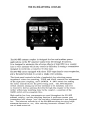
THE FC-902ANTENNA
COUPLER
The FC-902 antenna coupler is designed £or low and medium power
applications
in the HF amateur bands £rom 160 through 10 meters .
It is designed to minimize
the adverse effects 0£ high SWR on a coaxial
line or wire antenna which may result in difficulty
in tuning a transmitter
designed to work into a resistive
50 ohm load.
The FC- 902 comes equipped with three UHF -type female
and a threaded terminal
to accept a single -wire antenna.
coax receptacles
The front panel controls include a bandswitch for selecting proper
impedance values for matching,
TUNE and LOAD controls for adjustment
of the capacitive
coupling,
and a POWER
& SWR switch for setting
the meter sensitivity
for the power being used.
The ANT SELECT
switch chooses among any of four antennas to be matched,
and if it
is desired to feed an antenna directly
through the. coupler to the trans mitter without any matching done by the coupler,
a position of the
BAND switch will accomplish
this .
High-quality
low-loss
components are used throughout the FC-902
antenna coupler,
and the matching function it perlorms
means your
transmitter
will always flseell the resistive
termination
it was designed
for.
The inherent selectivity
of the FC- 902 matching circuitry
helps
attenuate harmonics,
too, thus reducing harmonic-related
TVI or
out-of-band
emission.
,
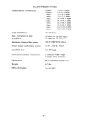
FC-
FREQUENCY
902
SPECIFICA
COVERAGE
TIONS
1.8-2. 0 MHz
1.9-2.4
MHz
3. 5 -4. 0 MHz
7 .0 -7 .5 MHz
10.0-10.5
MHz
14.0-14.5
MHz
18.0-18.5
MHz
21.0-21.5
MHz
24.5-25.0
MHz
28.0-29.7
MHz
160mL
160mH
BOm
40m
30m
20m
17m
15m
12m
10m
Input
50-75
impedance
Max. variation
impedance
Maximum
Power
transmitter
meter
Insertion
in load
calibration
ohms
50 ohm in:
75 ohm in:
power
10 -250 ohms
18-300 ohms
500 W PEP @ 50 ohms
scales
2SW.
loss
2S0W.
SO OW
0.5 dB max.
3 coaxial
Rear panel antenna connections
1 single
IIUHF
wire
II type
terminal
Dimensions
208 (L)x152(H)x324(D)
Weight
6 .5 kg .
SWR calibration
To 4:1 SWR
-2-
mm.
FRONT
PANEL
CONTROLS
.
TUNE
The TUNE control is a dual capacitor to provide capacitive
adjustment
of the coupling -between the transmitter
and the impedance established
by the BAND switch and the LOAD control.
The TUNE and LOAD
controls are adjusted for minimum
SWR .
BAND switch
The BAND switch selects the inductance required to accomplish
matching on the band in question.
The operator
should select the
BAND switch position which best covers the portion 0£ the band
being used.
The DIRECT position 0£ the BAND switch connects the
transmitter
directly
to the antenna, bypassing the FC-902 matching
circuitry,
but permitting
measurement
0£ the SWR on the line at
that point.
SWR SET
This control is used to calibra.te the SWR METER:
the SWR may
be read accurately
by adjusting the SWR SET control for full deflection
of the FWD POWER meter with the POWER & SWR switch in the
SWR SET position.
LOAD
The LOAD control is connected to a variable
capacitor which adjusts
the couplin,g between the antenna feedline and the impedance presented
by the BAND switch inductor and the TUNE control.
3-
ANT SELEC T
This switch selects the anteIUla to be matched.
The operator
has the choice of one of three coax-fed antennas or a single wire
anteIUla.
POWER
&SWR
switch
This switch is used to select the proper sensitivity
0£ the FWD POWER
meter £or the power being used, and to provide calibration
£or the
measurement
0£ SWR.
FWD POWER meter
The FWD POWER meter reads the output power
25 watts. 250 watts. and 500 watts maximum.
on three
scales of
SWR meter
When calibrated,
this meter provides accurate measurement
of SWR
for purposes of adjusting the LOAD and TUNE controls for the best
match.
.
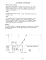
REAR PANEL
ANT
1, ANT
2, ANT
CONNECTIONS
3
These three £emale UHF -type connectors will accept the coaxial
£eedline £rom the antenna.
As well, a dummy load such as the
Y AESU YP -150 may be attached to one 0£ these connectors £or
tuning or test purposes .
WIRE
This threaded terminal
"Windom" type.
accepts
a single -wire
antenna such as the
GND
This terminal
should be connected to a good earth ground So as to
provide a DC path to ground £or stray currents.
and to reduce
I'RF in the shack" and ground looPS. etc. .that may make antenna
matching di£ficult.
This is particulary
important
in the case 0£
certain types 0£ single -wire antennas .
INPUT
The INPUT connector is another female UHF receptacle
for connection
between the FC- 902 and the RF output connector of the transmitter
or transceiver.
.../
~
/
COAXIALCABLE
/
/"""
DUMMY
LOAD
yp-
150
FC-902
TRANSCEIVER/
ANT2
-E)
LQJ
ANTJ
COAXIAL CABLE
(:)
INPUT
(7)
COAXIAL
-~-
CABLE
TRANSMITTER
ANTENNA
MA TCmNG
PROCEDURE
IT IS STRONGLY RECOMMENDED
THAT THE FOLLOWING
SECTION
BE READ IN ITS ENTIRETY
BEFORE ANY MA TCHING OF ANTENNAS
IS ATTEMPTED.
WffiLE A STRAIGHTFORWARD
PROCEDURE,
ANTENNA MATCHING WITH A COUPLER SUCH AS THE FC-902
INVOLVES A LOGICAL PROGRESSION OF STEPS, AND FAMILIARITY
WITH THE TOTALITY
OF THE FOLLOWING
SECTION WILL
CLARIFY
THE PROCEDURE IMMENSEL Y .
To summarize
the procedure that is followed in using the FC-902
antenna coupler to match a feedline to the transmitter,
the following
process takes place:
1) The proper inductance is chosen using the Band
swi tch .
2) The LOAD and TUNE controls are adjusted to
secure a minimum
SWR. Thses two controls
should be adjusted one at a time, so as to avoid
confusion as to the effect of any particular
adjustment.
A typical procedure to follow would
be to apply power, adjust the TUNE control for
minimum
SWR, then adjust the LOAD direction
either to the right or left.
Once the LOAD control has been changed, the TUNE control should
again be adjusted for minimum
SWR; if this
procedure improves
the SWR, it should be continued by further moving the LOAD control in
the same direction,
but if the initial change in
the LOAD control worsens the SWR, one should
try moving the LOAD control in the opposi.te
direction.
It will be clear to the operator when
the LOAD control is being adjusted in the right
direction.
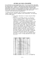
Figure
-6-
1
The reader is re£erred to Fig. 1, which contains the approximately
correct positions 0£ the BAND, LOAD,
and TUNE controls £or a
50 ohm load impedance,
such as that presented by a dummy load.
A dummy load is extremely
use£ul £or tuning up a transmitter
in
preparation
£or adjustment 0£ matching 0£ an antenna.
1£ the control
positions shown in Fig. 1 are utilized in conjunction with a 50 ohm
dummy load, only very minor adjustments
0£ the TUNE and LOAD
controls will be necessary for a per£ect match.
0£ course, a 50-ohm
dummy load should require no matching £or a per£ect match to a 50-ohn:
transmitter
output, but this information
is presented because the
control positions in Fig. 1 represent useful starting points £or
matching unknown impedances .
The following.
then. is a step-by-step
procedure to follow for the
matching of an antenna feedline that has not been matched previously.
I) Tune up the transmitter
in the normal way into a 50 -ohm dummy
load (if 50 ohm coax is used between the transmitter
and the FC-902)
or other Tesistive
50 ohm termination.
Reduce the gain control on
the transm"'ltter to a minimum,
and place the transmitter
in "standby'
for the moment.
2) Place the BAND, LOAD ~ and TUNE c.ontrols in the positions
indicated in Fig. 1 £or the £requency at which the line is to be
matched.
Place the ANT SELECT switch in the position which
corresponds
to the rear panel connector 0£ the antenna to be
matched.
Place the POWER & SWR switch in the SWR SET
position,
and place the SWR SET knob in the 12:00 position.
3) It is desirable
to make preliminary
matching adjustments
with as little transmitter
output power as possible.
Place the
transmitter
in the "tran$mit"
condition,
and SloWly advance
the outpUt level until deflection
0£ the FWD POWER meter is
observed.
Adjust the SWR SET control to line up the meter
needle 0£ the FWD POWER meter with the SWR SET position
at the far right end 0£ the FWD POWER meter,
using the minimwn
power necessary to accomplish
this.
With the needle in the SWR
SET mark 0£ the FWD POWER meter,
the SWR meter will accurately
read the SWR .
4) Adjust the TUNE control for minimum
reading on the SWR
meter.
If necessary,
adjust the SWR SET control and/or transmitter power to ensure'proper
calibration.
Once the Ildip'l has
been found using the TUNE control,
move the LOAD control either
to the left or right, by a sma~l amount.
Adjust the TUNE control
for a "dip" again, and if the SWR improves
(again, make sure that
you are reasonably well calibrated)
move the LOAD control slightly more in the same direction.
Again "dip" the TUNE control,
and
continue this procedure until no further improvement
is noted.
If
the initial direction
of adjustJ:nent of the LOAD control worsened the
SWR, move it an equal direction
from the starting point IN THE
OPPOSITE DIRECTION
and follow the above procedure with
succes sive adjustment of the TUNE and LOAD controls .
5) Once the initial procedure has been followed to yield a nearperfect match, the POWER & SWR switch may be placed in the
position which most closely corresponds
to the transmitter
output
power expected.
The transmitter
may then be adjusted for full
power {some adjustment
of the transmitter
load and tune controls
may be necessary during matching adjustments),
and the FC-902
LOAD and TUNE controls may be adjusted to yield zero deflection
of the SWR meter.
When the POWER & SWR switch is not calibrated
with the SWR SET controls,
the SWR meter will not accurately
read
the SWR, but it will. indicate minimum
reflected power .
NOTES ON ANTENNA
MA TCHING
I) It is very important
that the maximum time limits during tune -up
conditions for the transmitter
are not exceeded.
This is particularly
important
when the transmitter
is being used at full power.
2) It should be noted that any matGhing per£ormed by the FC-902
in the shack will have no e££ect on the losses due to S"W-Ron the
coaxial line between the FC- 902 coupler and the antenna.
The
operator should consult one 0£ the popular antenna handbooks to
determine whether or not matching between the coaxial line and
the antenna must be per£ormed at the antenna. For example, a
100 -£OOt length 0£ RG8A fu coax typically
has a loss (with 1:1
SWR between it and antenna) 0£ less than 1 dB at 21 MHz.
If
this line is operated wiftJ. a~
S'N"R due to a. low or high antenna
impedance,
the loss due to SWR will increase roughly 0. S dB,
an imperceptible
degradation
as compared to the 1:1 condition.
In this case, attempts to reduce the 3:1 SWR at the antenna end
would serve no use£ul purpose as £ar as reducing losses in the
coax, through matching with the FC-902 would improve the
impe.:lance presente;j to the transinitter
01.ltpi.lt cjrcuitry.
~vel.
i£ a SOO-£oot leJ.1gth of the above coax 'Nere used instead 0£ only
loo feet, smnewhat more than 1 dB 0£ loss wo'.lld o,-;cur in +.he
coax due to the 3:1 SWI.-{, possibly justi£ying further matching
attem;Jts :3.t the antp:'1"1."
3) Whe:.'l using ~ transce.lver
such as the FT -30lD which has
protection
for the O1.ltput transistors
again3t high SWR, it can
be seen that the rnatcl'ling action of the FC-902 will en3Ure that
a 50 Jhm load is presented to the O1.ltput circuitry,
thus ensuring
full transmj.tter
power .
4) It may b,~ useful for the operator to record in a noteboo~< t.~e
proper TUNE and LOAD positions for a particular
ante:.L'la for
q".lick reference.
AlteTnatively,
approprIate
lab,~ls may be
fabricated
and applied to the FC-902 front p.3.nel showing the
proper positions of the TUNE ani LOAD co~trols .
-8-
.
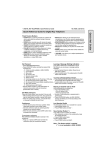
PARTS
LIST
~
YAESU
V
E8190182H(8206-F)