1
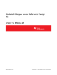
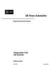
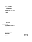
Electric Rotary Valve EN and SN SERIES User Manual TABLE OF CONTENTS Contents TABLE OF CONTENTS ................................................................................................................. 2 VALVE CONFIGURATIONS .......................................................................................................... 3 Flow Control Configurations – 4 Position Valve ...................................................................... 3 Flow Control Configurations – 6 Position Valve ...................................................................... 3 Flow Control Configurations – 8 Position Valve ...................................................................... 4 Flow Control Configurations – 10 Position Valve .................................................................... 4 Flow Control Configurations – 12 Position Valve .................................................................... 4 Valve Part-Number Structure .................................................................................................. 5 Valve Head Assembly ................................................................................................................ 6 Features ................................................................................................................................. 6 Optical Position Sensor .............................................................................................................. 6 Features ................................................................................................................................. 6 Stepper Motor ............................................................................................................................ 7 Features of BCF Supplied Motors (RV-SN2 series valves only) ............................................. 7 Motor Interface ........................................................................................................................... 8 GETTING STARTED: Quick-Start Application Guide ................................................................. 10 Getting Started: RV-EN0 Series – Valve Head Assembly ....................................................... 10 Getting Started: RV-SN2 Series – Valve Head Assembly + Stepper Motor ............................ 10 Getting Started: Recommended Operating Parameters ............................................................. 11 Motor Operating Speed ............................................................................................................ 11 Motor Microstepping for Optimal Port Alignment ...................................................................... 11 Motor Duty Cycle...................................................................................................................... 11 Getting Started: Electrical Connections ................................................................................... 12 Stepper Motor (wire colors for RV-SN2 series motors, supplied by BCF)............................. 12 Position Sensor Wires (Bio-Chem Fluidics Two-Channel Position Sensor) .......................... 13 Getting Started: Valve Installation ............................................................................................... 14 Valve Mounting Details ............................................................................................................ 14 Bulkhead Mounting Recommendations .................................................................................... 15 Getting Started: Fluid Port Fitting Interface ................................................................................. 16 Tightening Fittings .................................................................................................................... 16 Valve Port Sequencing ......................................................................................................... 17 MAINTENANCE ........................................................................................................................... 18 Valve Head Assembly .............................................................................................................. 18 Technical Specifications .............................................................................................................. 19 Valve ........................................................................................................................................ 19 Functional Specifications ...................................................................................................... 19 Warranty ...................................................................................................................................... 20 Life Support Policy ................................................................................................................... 20 Bio-Chem Fluidics Electric Rotary Valve Quick-Start Guide Page 2 VALVE CONFIGURATIONS The standard configurations of these valves have two types of flow control arrangements – switching and distribution. Each configuration is shown below. All configurations provide inert flow paths (using TFE-based materials for the wetted components), making them compatible with a wide range of liquid media. Port locations and sequencing order are illustrated in the diagrams below. Each diagram is shown with the valve in the “Home” position. Flow Control Configurations – 4 Position Valve 4 port switching 4-way selection / distribution Axial Port 4 1 4 1 3 2 3 2 4 port switching 4-way selection / distribution Flow Control Configurations – 6 Position Valve 6 port switching 6-way selection / distribution 6 1 6 2 5 4 3 6 port switching Axial Port 1 2 5 4 3 6-way selection / distribution Bio-Chem Fluidics Electric Rotary Valve Quick-Start Guide Page 3 Flow Control Configurations – 8 Position Valve 8-way selection / distribution 1 Axial Port 2 8 7 3 4 6 5 Flow Control Configurations – 10 Position Valve 10-way selection / distribution 1 10 Axial Port 2 9 3 8 4 5 7 6 Flow Control Configurations – 12 Position Valve 12-way selection / distribution 12 1 Axial Port 2 3 11 4 10 5 9 8 7 6 Bio-Chem Fluidics Electric Rotary Valve Quick-Start Guide Page 4 Valve Part-Number Structure The valve part-number structure is as follows: RV – aaa – bbb – cccc The options are: RV – rotary valve (universal) aaa EN0 – valve head assembly only SN2 – valve head assembly with stepper motor bbb J4C – switching valve, 4-port – rated at 200 psi lifetime pressure J6B – switching valve, 6-port – rated at 150 psi lifetime pressure S4C – selection / distribution valve, 4-way – rated at 200 psi lifetime pressure S6B – selection / distribution valve, 6-way – rated at 150 psi lifetime pressure S8B – selection / distribution valve, 8-way – rated at 150 psi lifetime pressure SAB – selection / distribution valve, 10-way – rated at 150 psi lifetime pressure SCB – selection / distribution valve, 12-way – rated at 150 psi lifetime pressure cccc PTHB – PTFE body / CTFE rotor / Ø.032” orifice size / ¼”-28 port fittings PTNB – PTFE body / CTFE rotor / Ø.052” orifice size / ¼”-28 port fittings PTTB – PTFE body / CTFE rotor / Ø.096” orifice size / ¼”-28 port fittings Bio-Chem Fluidics Electric Rotary Valve Quick-Start Guide Page 5 SYSTEM COMPONENTS ESD Sensitive The sensor PCBs are sensitive to electrostatic discharge (ESD). The user must take appropriate precautions to protect against ESD during handling and installation. The BCF Electric Rotary Valve is made up of a Valve Head Assembly and an optional Stepper Motor. Valve Head Assembly The Valve Head Assembly is made up of five (5) primary components: 1. Body (PTFE) 2. Rotor (CTFE) 3. Coupling (aluminium) 4. Optical Position Sensor 5. Housing (POM) Features Chemically inert wetted surfaces – PTFE Body + CTFE Rotor Coupling is precision-mated to Valve Rotor (direct inline drive) Coupling incorporates encoder disc for optical position sensing Coupling mates directly to motor’s drive shaft, secured via allen head set-screw Housing encases the optical encoder assembly and secures PCBs into position Housing secures both the valve assembly and the driving motor into position Optical Position Sensor A two-channel optoelectronic position sensor and optical encoder disc are incorporated into the valve. This position sensor allows for referencing the “Home” position after the unit is powered up, and for signalling that the valve has reached a valid “Port” position. This sensor must be powered externally and its signal processed externally. This sensor is an open-collector circuit. For further details on the on the electronic connections, see page 10. Features Operates on +5 VDC power input 2-Channel TTL output signal – one channel for “Home” / one channel for “Port” Bio-Chem Fluidics Electric Rotary Valve Quick-Start Guide Page 6 OPTICAL SENSORS PORT INDICATORS HOME INDICATOR HOME = PORT 1 Bio-Chem Fluidics Two-Channel Position Sensor and Encoder Disc Stepper Motor The Bio-Chem Fluidics Electric Rotary Valve is designed to be driven by a NEMA 17 hybrid stepper motor. Each valve requires a motor rated at a MINIMUM holding torque of 96 N-cm at the recommended operating voltage and motor speed. The RV-SN2 series valve is supplied with a motor pre-installed. The RV-EN0 series valve is not supplied with a motor, and it is the responsibility of the customer to ensure the appropriate power / torque motor is installed per BCF recommendations (refer to table below and Motor Interface section on next page). Features of BCF Supplied Motors (RV-SN2 series valves only) NEMA 17 frame configuration, two phase hybrid design Wired as bipolar series, 4 lead-wire connection 1.8° step angle, optimized for microstep operation Quad-stack motor design, 1.8 A RMS current Motor Specifications Specification Rated RMS phase current Peak - Peak phase current (see note below) Phase resistance at 20°C Phase inductance (typ.) Holding torque (typ.) Parameter Units Value IRMS RATED A 1.8 IP-P A 2.6 RCOIL Ω 2.6 mH 5.2 N-cm 96.0 in-oz 136 Insulation class B Connection wires 4 Step angle ° 1.8 Although the motors can be operated at a minimum voltage of 12 VDC, it is recommended to operate these motors using ≥24 VDC in order to achieve optimal motor torque and performance for reliable valve operation. Bio-Chem Fluidics Electric Rotary Valve Quick-Start Guide Page 7 The current ratings provided for the stepper motors are RMS ratings, not Peak-to-Peak ratings. For the 1.8 ARMS quad-stack motor, it is recommended that the power supply be capable of supplying a minimum of 2.6 amps current, as the motor can draw up to 2.545 AP-P. ESD Sensitive Due to the sensitivity of the Electric Rotary Valve’s position sensor electronics, it is required to attach an earth-ground to the motor casing. RV-SN2 series valves come equipped with an 18AWG insulated ground wire pre-installed. It is recommended to use an equivalent grounding wire on RV-EN0 series valves. Motor Interface The BCF Electric Rotary Valve is designed to mate to a NEMA 17 hybrid stepper-motor as the driving source. The valve’s Housing fastens to the stepper-motor frame using four (4) M3x25 socket-head cap screws (M3 lock washers also recommended) on a 40 mm (1.58”) pitch circle diameter. The following diagram illustrates representative dimensions of the NEMA 17 stepper motors to which the valve is designed to mate (including the recommended shaft dimensions). (All dimensions are in millimeters). Interface Dimensions –Stepper Motor When attaching a motor on RV-EN0 series valves, it is important that the flat edge of the motor shaft is aligned with the set screw prior to motor installation. The set screw is pre-installed in the Coupling inside of the valve’s Housing (visible through the Access Port hole in the Housing). Bio-Chem Fluidics Electric Rotary Valve Quick-Start Guide Page 8 When attaching a motor on RV-EN0 series valves, ensure the encoder sensor wires do not get pinched. Not only can the wires be damaged, but this can also impact the alignment of the motor shaft connection. It is important to verify the wires remain inside the Housing’s wire channel. When fastening a motor on RV-EN0 series valves using the recommended hardware, care must be taken when tightening the screws. The screws mount through the four (4) holes in the valve’s Housing and screw directing into the M3 threaded holes in the motor. It is suggested to first loosely fasten all of the screws and then secure them with a torque of 54-58 in-oz (38-41 N-cm). Once a motor is fastened on RV-EN0 series valves, the motor shaft needs to be secured using the M3 set screw. It is important that the flat edge of the motor shaft is aligned with the set screw prior to motor installation. The set screw is accessible through the Access Port hole in Housing. It is recommended to secure the set screw with a torque of 54-58 in-oz (38-41 N-cm). Bio-Chem Fluidics Electric Rotary Valve Quick-Start Guide Page 9 GETTING STARTED: Quick-Start Application Guide ESD Sensitive The sensor PCBs are sensitive to electrostatic discharge (ESD). The user must take appropriate precautions to protect against ESD during handling and installation. Setting up the Bio-Chem Fluidics Electric Rotary Valve will depend upon the valve configuration. This quick-start guide will explain what is needed to set up and operate the valves. Getting Started: RV-EN0 Series – Valve Head Assembly In order to use an RV-EN0 series valve, it is necessary to install and apply the appropriate power / torque motor and the appropriate driver / controller electronics to operate the motor. Refer to the Motor Specifications section on page 7-9 for required motor parameters. Getting Started: RV-SN2 Series – Valve Head Assembly + Stepper Motor The RV-SN2 series valve is supplied with a NEMA 17 stepper motor pre-installed. In order to use an RV-SN2 series valve, it is necessary to supply the appropriate drive and control electronics to operate the stepper motor. This can be accomplished by either employing an offthe-shelf driver / controller module or by setting up a custom control board with the appropriate driver and controller ICs. Driver and controller ICs are available from a variety of sources. See page 9 for the electrical specifications of the motors provided on the RV-SN2 series valves. The power supply must be capable of supplying a minimum of 2.6 amps current, as the motor can draw up to 2.545 AP-P. In some cases, programming software associated with the ICs can be used to cap the current provided to the motor should this be needed for a particular power supply. Use the integrated position sensor to locate the valve’s “Home” and “Port” positions (reference details on page 8). along with additional microstep adjustments to ensure optimal alignment of the ports. . Bio-Chem Fluidics Electric Rotary Valve Quick-Start Guide Page 10 Getting Started: Recommended Operating Parameters The following operating parameters are recommended for use with the BCF Electric Rotary Valve. Following these guidelines will optimize the lifetime performance of the valve and maintain the valve’s sealing ability over its full life. Motor Operating Speed The following table outlines recommended motor operation speeds. In order to maintain the valve’s sealing ability over its lifetime, the valves should not be operated above these speeds. Furthermore, because the angular travel is short, maintaining speeds at or below those recommended below will provide optimal control accuracy for rotor positioning. Note that acceleration and deceleration are not included in the port to port times, and therefore times are approximate. Valve Configuration Angular Move Distance Suggested Motor Speed Resultant Move Time Port-to-Port 4-Way 90° 60 RPM 250 msec 6-Way 60° 40 RPM 250 msec 8-Way 45° 40 RPM 180 msec 10-Way 36° 40 RPM 150 msec 12-Way 30° 40 RPM 125 msec Motor Microstepping for Optimal Port Alignment Set the default microstepping value to “16” in the control program. Use an additional “24” microstep adjustment after “Home” or “Port” signals are detected for optimal alignment of the port position. Microstepping methods vary from controller to controller. Utilizing and programming these methods are the responsibility of the customer. Motor Duty Cycle The following nominal and maximum duty cycles are recommended. Operating above the maximum duty cycle will shorten the valve life significantly. Consequently, lower duty cycles will minimize valve wear and prolong the life of the valve. Duty Cycle – Nominal: Duty Cycle – Maximum: 12.5% 25.0% Depending on actual motor speeds, the nominal equates to approximately one port-to-port move every two seconds, while the maximum equates to approximately one port-to-port move every one second. Bio-Chem Fluidics Electric Rotary Valve Quick-Start Guide Page 11 Getting Started: Electrical Connections ESD Sensitive The sensor PCBs are sensitive to electrostatic discharge (ESD). The user must take appropriate precautions to protect against ESD during handling and installation. Stepper Motor (wire colors for RV-SN2 series motors, supplied by BCF) Wire Color Wire Type & Gauge Coil Red UL 3265 AWG 26 Motor coil A start Blue UL 3265 AWG 26 Motor coil A end Green UL 3265 AWG 26 Motor coil B start Black UL 3265 AWG 26 Motor coil B end RV-SN2 series valves also come with ground wire pre-installed on the motor case. This wire is Green/Yellow, UL 1007 AWG 18, and must be secured to an earth-ground. CAUTION! Never connect or disconnect a motor to a control board with power applied. This may result in damage to the control board and/or motor. Bio-Chem Fluidics Electric Rotary Valve Quick-Start Guide Page 12 Position Sensor Wires (Bio-Chem Fluidics Two-Channel Position Sensor) Wire No Name Function Wire Color and Type 1 Home Home Signal 0 to 1V when at Home position 1.5 to 5V when not at Home position Black UL1007 24 AWG 2 Port Port Signal 0 to 1V when at Port position 1.5 to 5V when not at Port position Red UL1007 24 AWG 3 GND Signal Ground Blue UL1007 24 AWG 4 +5V +5VDC Supply Input *SEE NOTE BELOW Green UL1007 24 AWG CAUTION! The position sensor MUST be operated using an external 5VDC power supply connected to the green wire. If more than 5VDC is applied to the green wire the optical position sensor board may fail instantly and permanently without warning. If the valve is used with boards that do not have pull down resistors installed in their general purpose inputs (GPI), the “Home” (black) and “Port” (red) signals should both have separate 10KΩ pull-up resistors wired to them. Bio-Chem Fluidics Electric Rotary Valve Quick-Start Guide Page 13 Getting Started: Valve Installation Valve Mounting Details The Electric Rotary Valve can be either base-mounted or bulkhead-mounted. Base-mounting involves three (3) M3 screws; bulkhead-mounting involves several mounting patterns involving seven (7) total M3 screws. The valve should be mounted with the Position Sensor and Motor wires arefacing down. The following diagram illustrates the relevant mounting dimensions for all valves (dimensions are in inches). Note that a 6 way switching valve is shown, but all valve head heights are given in the drawing. Other dimensions are the same. Note that an additional 1” in minimum length should be provided behind the motor for controller board and associated cables. Overall Dimensions and Mounting Positions – Ø1.24” Valve Head Bio-Chem Fluidics Electric Rotary Valve Quick-Start Guide Page 14 Bulkhead Mounting Recommendations When mounting a valve such that the valve head protrudes through a bulkhead opening. Outer diameters of the valve heads are listed below. Additional clearance is required for easy valve installation: 4 way and 6 way except 0.096” orifice: 1-1/4” 6 way .096” orifice: 1-1/2" 8 way except 0.096 orifice: 1-5/16” 8 way 0.096 orifice through 12 way: 1-3/4" Additionally: The recommended screw clearance-hole size is Ø0.128” (3.3 mm). The maximum size screw head that can be accommodated is Ø0.240” (6.10 mm). The maximum size washer that can be accommodated is Ø0.360” (9.14 mm). The maximum screw insertion depth is limited to 0.472” (12.0 mm). All bulkheads or brackets must be designed to properly support the weight of the valve. Further specific details regarding these mounting configurations may be found on Installation Drawings available through Bio-Chem Fluidics. Bio-Chem Fluidics Electric Rotary Valve Quick-Start Guide Page 15 Getting Started: Fluid Port Fitting Interface All standard RV series valves employ female ¼-28 UNF flat bottom ports that mate to standard male ¼-28 flat bottom fittings. Tightening Fittings Caution Fittings must be torqued to 11-13 N-cm (16-18 in-oz) in the order suggested below or leakage and/or premature failure may occur. It is important when connecting fittings into the body’s ports to first loosely install all fittings and then tighten opposing fittings together, in progressive steps, increasing the thread engagement at each step as one works across the body. Taking this precaution will prevent unduly distorting the PTFE body. The required torque of 11-13 N-cm (16-18 in-oz) is adequate to ensure proper long-term sealing between the fitting and the port bottom. Tightening fittings beyond this level can distort the inner section of the body, squeezing the rotor and adding excessive torque load on the motor (identified by noise from the motor). Bio-Chem Fluidics Electric Rotary Valve Quick-Start Guide Page 16 Valve Port Sequencing The following diagrams illustrate the port sequencing order. Where applicable, both switching and selection valves are shown. This is the sequence as seen when looking straight on at a valve with the vmotor away from the observer. 4 1 4 1 3 2 3 2 1 6 2 5 10 2 1 12 2 9 7 3 4 1 8 2 5 3 4 1 6 3 4 8 4 5 2 3 11 4 10 3 6 1 7 6 5 5 9 8 7 6 CAUTION: Avoid multiple removals and re-installations of the fittings, as doing so will reduce the intended working life of the valve’s ports. PTFE is a relatively soft material which can be damaged if care is not taken when installing/removing the fittings. If one of the ports in the PTFE body is accidentally cross-threaded and/or damaged, it is very likely to result in permanent leakage at that port. Bio-Chem Fluidics Electric Rotary Valve Quick-Start Guide Page 17 MAINTENANCE Valve Head Assembly Due to the inherent nature of the Virgin PTFE used to produce the body (stator) of these valves, the valve’s body / rotor assembly will experience a slight release of PTFE fibers from the body over time. This may be more pronounced in selection valves than in switching and combination valves. This is primarily because less fluid is flowing through the overall valve at any given time (more fluid equating to greater lubrication). Some fibers will remain firmly secured to the body at the inner orifice interfaces (where the body mates to the rotor), while some fibers will wash out into the fluid stream. Applications that employ pressures higher than 25 psi should see most of the fibers wash out into the fluid stream. This may dictate the need for a downstream filter in an instrument’s flow path. A 50 micron (or finer) filter is recommended. Residual fibers that remain attached should not cause more than 3% flow restriction over the life of the valve for standard-sized orifices (.054”). Applications that employ pressures less than or equal to 25 psi will see most of the fibers remain secured to the body. A downstream filter may still be desirable for the small amount of fibers that do wash out. In these applications, the amount of fiber blockage will continually build up until significant blockage may be present toward the end of the valve’s life. However, testing has shown that this blockage should introduce no more than approximately 10% flow restriction. The following preventative maintenance (PM) routine is required to remove built-up fibers that have accumulated in valves used for low pressure applications: 1. Flush water at 50 psi for 2 minutes through each orifice. 2. Repeat this routine a minimum of every 100,000 cycles, or more frequently if desired. This routine will minimize the amount of fiber build-up at each orifice, though not eliminate it entirely. It should, however, restore flow to within 3% of original flow. If a downstream filter is employed, it is recommended that it be cleaned every 100,000 valve cycles, or as required. Bio-Chem Fluidics Electric Rotary Valve Quick-Start Guide Page 18 Technical Specifications Valve Functional Specifications Wetted Materials: Virgin PTFE (stator / body); CTFE (rotor) Fluid Connection Ports: ¼ - 28 UNF, flat bottomed Operating Pressure: 4-way: up to 200 psi (13.6 bar, 1.379 MPa) 6-way: up to 150 psi (10.3 bar, 1.034 MPa) 8-way: up to 150 psi (10.3 bar, 1.034 MPa) 10-way: up to 150 psi (10.3 bar, 1.034 MPa) 12-way: up to 150 psi (10.3 bar, 1.034 MPa) Flow Path / Orifice Diameter Options: .032” (0.81 mm) .052” (1.32 mm) .096” (2.44 mm) Bio-Chem Fluidics Electric Rotary Valve Quick-Start Guide Page 19 Warranty Bio-Chem Fluidics warrants the RV series rotary valves to be free from defects in material and workmanship, and for conformance to published specifications under normal use and service, for a period of one year from the date of manufacture. Bio-Chem Fluidics’ sole obligation and liability under its warranty is limited to the repair or replacement (at Bio-Chem Fluidics’ discretion) at its factory of any rotary valve which proves defective. Bio-Chem Fluidics makes no other warranty, express or implied, of the rotary valve, including, without limitation, implied warranties of merchantability and fitness for particular purpose, and all such warranties are expressly excluded. Bio-Chem Fluidics reserves the right to modify published specifications at any time at its sole discretion. Full details of the applicable warranty can be found in the Bio-Chem Fluidics Inc. Terms and Conditions of Sale. Contact Bio-Chem Fluidics for further inquiries. Life Support Policy Bio-Chem Fluidics does not authorize or warrant any of its Electric Rotary Valves for use in life support systems. Life support systems are defined as equipment intended to support or sustain life, whose failure to perform can be reasonably expected to result in personal injury or death. Bio-Chem Fluidics Electric Rotary Valve Quick-Start Guide Page 20 BCF ERV Quick-Start Guide – 9 June 2015 www.biochemfluidics.com Bio-Chem Fluidics Inc 85 Fulton Street, Boonton NJ 07005 USA t: 973 263 3001 f: 973 263 2880 e: [email protected] Bio-Chem Fluidics Technology (Shanghai) Co. Ltd South Metropolis Industrial Park, Jindu Road, Minhang District, Shanghai, PRC 201108 t: +86 21 61519058 f: +86 21 61519090 Bio-Chem Fluidics Electric Rotary Valve Quick-Start Guide Page 21