1
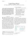
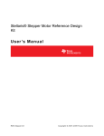
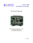
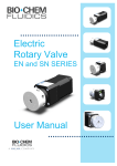
QuadMotor Shield
User Manual
Thank You
Thank you for purchasing your Shieldstudio QuadMotor Shield. At Shieldstudio, we value your input as a customer of
our products. Please feel free to contact us at [email protected] with ideas and/or questions about your product.
Disclaimer
Shieldstudio is not responsible for special, incidental or cnsequential damages under any legal theory, including lost
profits, downtime, goodwill, damage to or replacement of equipment or property.
Shieldstudio is also not responsible for any personal damage, including that to life and health, resulting from use of our
products. The user takes full responsibility for each of our product application, no matter how life-threatening it may be.
Shieldstudio is not liable for any injuries sustained due to the use of or improper use of products purchased from
Shieldstudio.
Shieldstudio complies with the personal information acat of Alberta http://pipa.alberta.ca/index.cfm
QuadMotor Shield
1
Description
The QuadMotor shield is an interface board designed to allow an Arduino microcontroller to control DC motors. The
board uses a pair of L293 Dual H-Bridge driver circuits to drive up to 4 separate DC motors. The QuadMotor shield can
be used as the motor driver for a robotic platform that uses an Arduino microcontroller board. The QuadMotor shield
uses the L298 to allow a motor supply voltage of up to 46V and a DC current of up to 4A DC on an individual channel.
On-board reverse voltage protection diodes are provided using discrete 1N5819 Schottky diodes.
Design Features
Extra wide traces are used for the motor power connections. A large ground plane reduces the amount of generated
noise. A two-sided board is used to keep the costs down. Screw terminal connections are provided for easy swapping
of the power connections. Pass through connectors are used to allow easy access to all of the signals provided by the
Arduino microcontroller board. An on-board reset button is provided as the shield will most likely cover the existing
Arduino reset button. Some space is provided to allow an external heat-sink to be bolted onto the L293 interface chips.
Multiple power options for the motor power supply are provided and are easily configured.
Compatibility
The QuadMotor shield is designed to be used with the Arduino family of microcontroller boards. The QuadMotor shield is
compatible with the Duemilanove, Diecimila and other Duemilanove and Diecimila compatible boards eg. Freeduino.
Pins Used
D2 - D13 Gnd
RESET Digital I/O pins
Pins Not Used
Rx, Tx
AN0 - AN6
3.3V
Aref
6pin ISP header
QuadMotor Shield
UART Rx and Tx signals
Analog Input pins (you may use them to connect analog sensors)
2
Power Options
The QuadMotor has three possible
power options for the DC motors.
External Power - an external power
supply can be used to drive the DC
motors. To use external power,
remove any jumpers from the power
jumper JP1 and connect the external
power to the connector labelled X3.
When viewing the X3 connector from
the edge of the board, the left side is
Ground while the right side is
+Vmotor (schematic +12V).
Vin Power - the power for the
motors may be provided directly from
the Vin power supplied to the
Arduino. To use power from Vin,
disconnect any external power on X3
and connect a jumper (supplied)
between pins 2 and 3 on JP1.
+5V Power - the power for the
motors may be provided directly from
the on-board +5V regulator of the
Arduino board. To use the +5V
power, disconnect any external
power on X3 and connect a jumper
(supplied) between pins 1 and 2 on
JP1.
Please note - when using the +5V Power option, the total current required by the Arduino and the DC
motors must not exceed the maximum current provided by the on-board regulator. Some Arduino boards
are populated with a 500 mA regulator while others may be modified to handle a 1A regulator.
Also note - when DC motors are first started, the initial surge current may draw more current than the
regulator will allow. When this happens, the regulator may shut-down (for safety) which will cause the
Arduino to reset and start your program over again.
QuadMotor Shield
3
Interface
Connectors X1 and X2 are used to interface to the DC motors.
The polarity is not critical as these can be flipped easily (by swapping the motor connections) or they can be easily
swapped in software.
QuadMotor Shield
4
!"#$%&
'#(")&*&!+,-+ .+/&%0
QuadMotor Shield
Schematic
5
Software
Here is some sample code to use with the QuadMotor shield (for a more advanced software driver, check-out
shieldstudio.com).
// Initialize QuadMotor shield
void setup( )
{
// disable all L293 outputs
digitalWrite(3, LOW);
digitalWrite(9, LOW);
digitalWrite(11, LOW);
digitalWrite(10, LOW);
}
// Motor1 enable=10, motor=12,13
void motor1_stop( )
{
digitalWrite(10, LOW);
digitalWrite(12, LOW);
digitalWrite(13, LOW);
digitalWrite(10, HIGH);
}
void motor1_forward( )
{
digitalWrite(10, LOW);
digitalWrite(12, HIGH);
digitalWrite(13, LOW);
digitalWrite(10, HIGH);
}
void motor1_reverse( )
{
digitalWrite(10, LOW);
digitalWrite(12, LOW);
digitalWrite(13, HIGH);
digitalWrite(10, HIGH);
}
QuadMotor Shield
6
void loop( )
{
int key;
// wait for a keypress
if (Serial.available( ) > 0)
{
key = Serial.read( );
// decode the keypress into motor control
switch( key )
{
case ‘x’:
motor1_stop( );
break;
case ‘f’:
motor1_forward( );
break;
case ‘r’:
motor1_reverse( );
break;
} // end switch
} // end if
} // end loop
QuadMotor Shield
7
Connecting the shield
The shield is designed to plug directly on-top of the Arduino microcontroller (or compatible) board.
1. Power up the Arduino without the shield (this is important!).
2. Create some software to make sure the board is initialized safely. (see software section).
3. Turn-off the Arduino.
4. Place the board on-top of the headers on the Arduino
5. Power up the Arduino with the shield.
6. Connect one motor (2 wires) to connector X1 or X2. Note - if your motor has more than 2 wires, then it might be a
servo instead of a DC motor. You will need to drive the servo with a different circuit.
X1-4
X1-3 X1-2
X1-1
X1-1 and X1-2 are used as a pair.
X1-3 and X1-4 are used as a pair.
X2-1 and X2-2 are used as a pair.
X2-3 and X2-4 are used as a pair.
X2-1
X2-2
X2-3 X2-4
7. After connecting one motor to the shield, connect the power to the QuadMotor shield. (see previous section on
power options).
8. Add more software to turn the motor on (forward), turn the motor on (reverse), stop the motor, idle the motor (see
software section).
9. Connect the remaining motors - adjust the software as necessary (or swap the motor connections) as you test out
each motor individually.
10.Play around and have fun!
QuadMotor Shield
8
Notes
The schematic shows 1N5817 Schottky Diodes - the board is actually built using 1N5819 Schottky Diodes. Each
1N5819 handles up to 40V of reverse voltage. This provides an extra margin of protection for the L298 driver circuits.
QuadMotor Shield
9