1
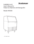
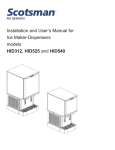
SCN60
User's Manual
Cabinet Dimensions
FLOOR DRAIN
ACCESS HOLE
3 7/8"
20 3/8"
3/4"
1/4" O.D. COPPER
WATER INLET
COMPRESSION
FITTING PROVIDED
22"
3/4" SHEET METAL DOOR FRONT - IF DOOR KIT INSTALLED
.63 MIN. CABINET DOOR
2 3/4"
2 3/8" DOOR KIT
AND HANDLE
14 7/8"
5 1/8"
33 3/8" MIN.
34 3/8" MAX.
29 1/4"
4"
3 1/4"
2 1/2"
2 3/4"
AIR OUT
115V
POWER CORD
AIR IN
1" LEG ADJUSTMENT
(4) PLACES
7 1/2"
11 5/8"
LEFT SIDE SVC.
ACCESS PANEL
DRAIN ACCESS - FLEXIBLE TUBING
3/8" I.D. PUMP MODEL (INCLUDED)
5/8" I.D. GRAVITY MODEL (NOT INCLUDED)
Scotsman Ice Systems are designed and manufactured with the highest regard for safety and
performance. They meet or exceed the standards of agencies like ETL.
Scotsman assumes no liability or responsibility of any kind for products manufactured by Scotsman that
have been altered in any way, including the use of any parts and/or other components not specifically
approved by Scotsman.
Scotsman reserves the right to make design changes and/or improvements at any time. Specifications
and designs are subject to change without notice.
May 2011
Page 3
SCN60
User's Manual
Location Recommendations:
The machine can be built into a cabinet. It is an air
cooled refrigeration system and so air flows in and
out of it through the grill at the bottom front. The
grill must not be blocked by any covering door or
other obstruction.
Drain Conversion: A gravity drain model can be
converted to a drain pump model by installing a
drain pump kit. The drain pump kit consists of a
drain pump, wiring harness and associated tubing.
The part number is A39462-021.
Installation Notes
Built In Situations: If a finished floor is to be
installed in the area after the ice machine has been
built in, shims the expected thickness of the floor
should be installed under the unit to keep the
machine level with the planned floor level.
Note: The water connection is at the back and adds
a few inches to the cabinet depth.
Installations on a slab: Use a pump model and
pump the water to the point of drainage. Pump
models will pump 1 story (10 feet) high.
Installations over a crawl space or basement:
Either gravity drain or pump model units may be
used, if there is not enough room behind the
machine for a drain/waste receptacle, the drain will
have to be below the floor.
Warm Air Out
Note: When installed in a corner, the door swing
may be limited due to handle contact with the wall
or cabinet face.
Air Intake
There are two models, one is a gravity drain type
and it must have a building drain connection below
the level of the drain tube at the back of the
cabinet; the other is a pump drain model which can
force drain water up a maximum of 10 feet,
allowing it to be located where a gravity drain isn’t
available.
All models require a water supply. Water supplies
vary in the degree of mineral content. High mineral
content water will require more frequent
maintenance. Water filtration may improve the
taste of the ice as well as cut down on some of the
mineral build up.
Kickplate Extension: In some situations the leg
levelers will be extended enough to become visible.
A kit to extend the kickplate over the legs is KKPF.
Cabinet Stability: In some free standing
installations it may be prudent to add a bracket that
secures the back of the cabinet to a wall. That kit
number is KATB.
May 2011
Page 4
SCN60
User's Manual
Plumbing - Pump Model
Drains
Water Supply
There are two types of ice machine models, one
that drains by gravity and one that has an internal
drain pump.
The recommended water supply tubing is ¼ inch
OD copper. Stainless steel flex or reinforced PCV
tube may also be used. Install an easily accessible
shut-off valve between the supply and the unit. This
shut-off valve should not be installed behind the
unit.
Drain Pump Model drain installation
1. Locate the coil of 3/8” ID plastic drain tubing
secured to the back of the unit.
2. Route the plastic drain tube from the back of the
unit to the drain connection point.
The drain connection point can be as high as 10
feet above the ice machine. The drain pump
includes a check valve to prevent re-pumping
water in the drain hose.
The water connection is at the back of the cabinet.
Connect using a compression fitting, one is
supplied tied to the water inlet tube at the back of
the cabinet. When built in: Coil enough tubing
behind the machine so it can be pushed into the
cavity without kinking the tubing.
IMPORTANT NOTE: Often an air gap is required
by local codes between the ice maker drain tube
and the drain receptacle.
Connect Water Supply
Here, fitting is supplied in
bag tied to tube
Pump Drain
Discharge
Tubing
May 2011
Page 8
SCN60
User's Manual
Plumbing: Gravity Drain Model
Caution: Restrictions in the drain system to the
machine will cause water to back up into the ice
storage bin and melt the ice. Gravity drain tubing
must be vented, have no kinks and slope to the
building drain. Air gaps are typically required by
local code.
6. Cut an 8” piece of 5/8” ID X 7/8” OD tygon (clear
plastic) tubing. Slide one end of the tube onto the
outlet of the barbed connector and secure with a
clamp. Leave the other end of the tube lying on the
floor of the base pan until the unit is positioned
over the floor drain.
1. Place the ice machine in front of the installation
opening. Adjust leveling legs to the approximate
height.
7. Route the drain tube. Either a) Insert the drain
tube through the base pan into the floor drain or b)
Route the drain tube through the hole in the lower
back panel and connect to barbed elbow and
secure with a clamp.
2. Insert drain tube through the routing hole in the
back panel.
8. Reinstall any panels removed to connect the
drain.
3. Remove the upper back panel if needed for
access to drain connection.
Water Supply
Note: If you are connecting a gravity drain model
and the drain opening has been located in the floor
under the base pan according to the pre install
specifications, follow steps 4 through 7a to drain
the unit through the base. If not, proceed to step
7b.
The recommended water supply tubing is ¼ inch
OD copper. Stainless steel flex or reinforced PCV
tube may also be used. Install an easily accessible
shut-off valve between the supply and the unit. This
shut-off valve should not be installed behind the
unit.
4. Remove the clamp and barbed elbow and take
off the plastic cover in the base pan below the drain
hose.
5. Connect a straight 5/8” barbed connector to the
drain hose, securing with the supplied hose clamp.
Drain Tubing
Inside Cabinet
Connect Water Supply
Here, fitting is supplied in
bag tied to tube
The water connection is at the back of the cabinet.
Connect using a compression fitting, one is
supplied tied to the water inlet tube at the back of
the cabinet.
When built in: Coil enough tubing behind the
machine so it can be pushed into the cavity without
kinking the tubing.
May 2011
Page 9
SCN60
User's Manual
Electrical and Start Up
The ice machine is supplied with a power cord. Do
not remove the grounding pin from the cord’s plug.
Do not use extension cords. Follow all codes.
Connect the machine to its own properly grounded
115 volt, 15 amp circuit.
1. If the electrical outlet for the ice maker is behind
the unit, plug in the unit.
Installation check list:
1. Has the unit been connected to the proper water
supply?
2. Has the water supply been checked for leaks?
3. Has the unit been connected to a drain?
4. Has the drain been tested for flow and leaks?
2. Position the unit in the installation opening.
3. Turn on the water supply. Make sure that the ice
maker is plugged in and the power is on.
5. Has the unit been connected to the proper
electrical supply?
6. Has the unit been leveled?
4. Slide unit into installation opening, paying careful
attention to water supply and drain connections. Do 7. Have all packing materials been removed from
not kink!
the machine?
5. Remove service panel for visual inspection.
8. Has the door covering been installed?
6. Pour a couple of quarts of water into the ice
storage bin; on drain pump equipped machines the
drain pump should start and water should pump
out. Check for leaks.
Initial Start Up
1. Turn on the water supply.
2. Switch on the electrical power.
7. Replace the service access panel.
8. Level the unit as needed.
3. Push and release the On/Off switch to start the
machine. The Ice Making light next to the On/Off
switch will glow Green.
Warm air will flow out of the left front grill.
It will take about 10 minutes for the ice machine to
begin dropping nugget ice into the storage bin. It is
normal for that ice to melt and ice will continue to
melt, but at a slower rate. It will take about 6 - 7
hours to fill up the ice storage bin. The storage bin
holds about 20 lb of ice when full.
Ice level control
The ice level control for the SCN60 is an ultrasonic
sensor, located above the ice storage area. It is
automatic and there is no adjustment to make.
When ice melts or is used, and the ice level drops
below a preset distance the control turns the ice
making system back on. It makes ice until the
preset level is reached. Placing your hand in the
unit to remove ice does not affect the ice level.
May 2011
Page 10