1
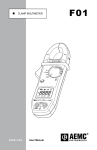
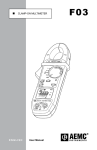
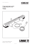
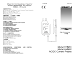
Clamp-On Multimeters
Models 701 and 703
USER MANUAL
Chauvin Arnoux, Inc. d.b.a. AEMC® Instruments
99-MAN-100071 Rev 03 01/98
Clamp-On Multimeters
Models 701 and 703
USER MANUAL
HOLD
MAX
~
V
~
A
HOLD
MAX
OFF
~
V
V
OFF
~
A
V
Ω
Ω
Ω
Ω
AEMC
I N ST R U M E N T S
+
_
–
Model 701
CLAMP-ON METER
MAX
HOLD
~
AEMC
I N S T R U M E N T S
+
-
Model 703
TRMS CLAMP-ON METER
MAX HOLD
RMS
!
600V ~
!
600V ~
+
¯¯¯
¯¯
¯¯¯
kHz
A
V
A
V
Ω
COM
Hz
COM
+
Owner’s Record
The serial number for the Clamp-On Multimeters Models 701 or 703 is
located inside the battery compartment of your instrument. Please
record this number and purchase date for your records.
CLAMP-ON MULTIMETER MODEL 701
CATALOG #1207.51
SERIAL #:
PURCHASE DATE:
DISTRIBUTOR:
CLAMP-ON MULTIMETER MODEL 703
CATALOG #1207.53
SERIAL #:
PURCHASE DATE:
DISTRIBUTOR:
99-MAN-100071
3rd Revision
Printed 01/98
AEMC® Instruments
by Chauvin Arnoux, Inc.
Table of Contents
Warning . . . . . . . . . . . . . . . . . . . . . . . . . . . . . . . . . . . . . . . . . . . . . 2
International Electrical Symbols . . . . . . . . . . . . . . . . . . . . . . . . . . . . 3
Receiving Your Shipment. . . . . . . . . . . . . . . . . . . . . . . . . . . . . . . . . 3
Packaging . . . . . . . . . . . . . . . . . . . . . . . . . . . . . . . . . . . . . . . . . . . 3
Description . . . . . . . . . . . . . . . . . . . . . . . . . . . . . . . . . . . . . . . . . . . 4
Specifications . . . . . . . . . . . . . . . . . . . . . . . . . . . . . . . . . . . . . . . . . 4
Controls, Model 701 . . . . . . . . . . . . . . . . . . . . . . . . . . . . . . . . . . . 10
Controls, Model 703 . . . . . . . . . . . . . . . . . . . . . . . . . . . . . . . . . . . 12
Digital Display Features. . . . . . . . . . . . . . . . . . . . . . . . . . . . . . . . . 14
AC Current Measurements . . . . . . . . . . . . . . . . . . . . . . . . . . . . . . 15
AC and DC Voltage Measurements . . . . . . . . . . . . . . . . . . . . . . . . 16
Max Value Measurements . . . . . . . . . . . . . . . . . . . . . . . . . . . . . . . 17
Resistance Measurements . . . . . . . . . . . . . . . . . . . . . . . . . . . . . . 17
Continuity Sound Test . . . . . . . . . . . . . . . . . . . . . . . . . . . . . . . . . . 18
Diode Tests . . . . . . . . . . . . . . . . . . . . . . . . . . . . . . . . . . . . . . . . . . 19
Frequency Measurements . . . . . . . . . . . . . . . . . . . . . . . . . . . . . . . 19
Maintenance . . . . . . . . . . . . . . . . . . . . . . . . . . . . . . . . . . . . . . . . . 20
Repair and Calibration. . . . . . . . . . . . . . . . . . . . . . . . . . . . . . . . . . 22
Technical and Sales Assistance . . . . . . . . . . . . . . . . . . . . . . . . . . . 23
Limited Warranty . . . . . . . . . . . . . . . . . . . . . . . . . . Inside back cover
Warning
These safety warnings are provided to ensure the safety of personnel and proper operation of the instrument.
• Read this instruction manual completely before attempting to use
or service this instrument and follow all the safety information.
• Use caution on any circuit: Potentially high voltages and currents may be present and may pose a shock hazard.
• The instrument must not be operated beyond its specified operating range.
• Safety is the responsibility of the operator.
• Never open the back of the instrument while connected to any
circuit or input.
• Always make connections from the instrument to the circuit
under test.
• Always inspect the instrument and accessory leads for serviceability prior to use, and replace defective parts immediately.
• Do not use the meter or any test leads, connectors, probes or
clips if they look damaged.
• Never use the clamp-on meters on electrical conductors rated
above 600 Vrms.
• Never make resistance measurements on a live circuit.
• Never make diode tests on a live circuit.
• Do not have voltage or current inputs connected at the same time.
2
Clamp-on Multimeters Models 701 & 703
International Electrical Symbols
This symbol signifies that the Models 701 and 703 are protected throughout by double or reinforced insulation. Only use
specified replacement parts when servicing the meter.
!
This symbol signifies CAUTION! and requests that the user
refer to the user manual before using the meter.
Receiving Your Shipment
Upon receiving your shipment, be sure that the contents are consistent
with the packing list. Notify your distributor of any missing items. If the
equipment appears to be damaged, file a claim immediately with the
carrier and notify your distributor at once, giving a detailed description
of any damage.
Packaging
Clamp-On Multimeter Model 701 (Cat. #1207.51) and Model 703
(Cat. #1207.53) include a 9 V battery, two 4-ft (1.2 m) test leads, a user
manual and a soft carrying case.
Clamp-on Multimeters Models 701 & 703
3
Description
The AEMC® Instruments Clamp-on Multimeter Models 701 and 703 are
general purpose professional clamp-ons. A strong mechanical case
design, quality materials (GE Lexan®), full ranges and compliance to
international safety and quality standards insure a professional and reliable measuring tool. Both models are autoranging, and provide AC
amperes and AC volts, plus DC volts, ohms, continuity with a beeper,
and a diode test function. The Model 703 also has a frequency function.
Both models are equipped with a large and complete 4000 count LCD
with annunciator symbols such as HOLD, Low Battery, Max etc. for easy
operation.
The Model 701 is average sensing RMS calibrated and designed for the
traditional average responding electrical systems. The Model 703 is a
True RMS clamp-on that provides RMS measurements for today’s nonlinear electrical environments. Both clamp-ons are supplied with test
probe terminated test leads, a soft carrying case, a 9 V battery and a
user manual.
We designed and built the Models 701 and 703 for reliability: the right
size; the right functions, display and performance; the right single-handed operation; the right professional tool.
Specifications
ELECTRICAL SPECIFICATIONS
Reference Conditions for following tables:
Accuracies are provided under the following reference conditions:
Temperature 18° to 28° C, 45 to 75% RH; battery voltage 9 V ± 0.1 V;
conductor centered in the probe jaws, earth’s magnetic field; no external AC magnetic or electrical field; sine wave 45 to 450 Hz.
4
Clamp-on Multimeters Models 701 & 703
Model 701
Model 703
Range
Resolution
Basic Accuracy
1 to 100 A
0.1 A
± 2% R ±5 cts
1 to 100 Arms
0.1 A
± 2% R ±5 cts(1)
Range
Resolution
Basic Accuracy
100 to 399.9 A
0.1 A
± 2% R
100 to 399.9 Arms
0.1 A
± 2% R(1)
Range
Resolution
Basic Accuracy
400 to 600 A
1A
± 2% R
400 to 600 Arms
1A
± 2% R(1)
Range
Resolution
Basic Accuracy
Input Impedance
1 to 40 V
0.1 V
± 1%± 2 cts
1 MΩ
1 to 40 Vrms
0.1 V
± 1%± 2 cts(2)
1 MΩ
Range
Resolution
Basic Accuracy
Input Impedance
40 to 399.9 V
0.1 V
± 1%R
1 MΩ
40 to 399.9 Vrms
0.1 V
± 1%R(2)
1 MΩ
Range
Resolution
Basic Accuracy
Input Impedance
400 to 600 V
1V
± 1%R
1 MΩ
400 to 600 Vrms
1V
± 1%R(2)
1 MΩ
AC Current*
AC Volts*
* A residual value of 7 counts may be displayed in the AC range.
1. Additional error with CF
CF from 1.5 to 2.5: 5% R
CF from 2.5 to 5: 8% R
Clamp-on Multimeters Models 701 & 703
2. Additional error with CF
CF from 1.5 to 3: 3% R
CF from 3 to 5: 8% R
5
Model 701
Model 703
Range
Resolution
Basic Accuracy
Input Impedance
1 to 40 V ± 2 count
0.1 V
± 0.5%
1 MΩ
1 to 40 V ± 2 count
0.1 V
± 0.5%
1 MΩ
Range
Resolution
Basic Accuracy
Input Impedance
40 to 399.9 V
0.1 V
± 0.5%
1 MΩ
40 to 399.9 V
0.1 V
± 0.5%
1 MΩ
Range
Resolution
Basic Accuracy
Input Impedance
400 to 600 V
1V
± 0.5%
1 MΩ
400 to 600 V
1V
± 0.5%
1 MΩ
Range
Resolution
Basic Accuracy
Open Voltage
Short Circuit Current
1 to 40
0.1Ω
± 1% R± 3 cts
4.4 V
1.2 mA
1 to 40
0.1Ω
± 1% R± 3 cts
4.4 V
1.2 mA
Range
Resolution
Basic Accuracy
Open Voltage
Short Circuit Current
40 to 399.9Ω
0.1Ω
± 1% R
4.4 V
1.2 mA
40 to 399.9Ω
0.1Ω
± 1% R
4.4 V
1.2 mA
Range
Resolution
Basic Accuracy
Open Voltage
Short Circuit Current
400 to 4 kΩ
1Ω
± 1% R
4.4 V
1.2 mA
400 to 4 kΩ
1Ω
± 1% R
4.4 V
1.2 mA
DC Volts
Ohms
6
Clamp-on Multimeters Models 701 & 703
Model 701
Model 703
NA
NA
NA
0 to 4 kHz
± 0.1% R ± 1 count
from A or V
0 to 40Ω
below 20Ω
± 10Ω R
4.4 V
1.2 mA
0 to 40Ω
below 20Ω
± 10Ω R
4.4 V
1.2 mA
0 to 4 V
0.001 V
4.4 V
1.2 mA
0 to 4 V
0.001 V
4.4 V
1.2 mA
Max Display Hold
Max Display Hold
Frequency
Range
Basic Accuracy
Hz pick-up
Continuity
Range
Beeper
Basic Accuracy
Open Voltage
Short Circuit Current
Diode Test
Range (DC)
Resolution
Open Voltage
Short Circuit Current
Additional Functions
Clamp-on Multimeters Models 701 & 703
7
General Specifications
Ranging:
Model 701: 6-position switch, autoranging
Model 703: 7-position switch, autoranging
Jaw size: Accommodates two 500 MCM (1.25" or 32 mm) or one 750
MCM (0.77" or 20 mm)
Battery: 9 V alkaline battery; automatic low battery indicator
Life:
Model 701: 180 hr typical
Model 703: 100 hr typical
Typical consumption:
Model 701: 2.5 mA without buzzer
Model 703: 3.5 mA without buzzer
Buzzer:
Continuous beep for the continuity sound test below 20Ω
Frequency: 2.5 kHz
Dimensions: 10 x 3.8 x 1.7” (252 x 97 x 44 mm)
Weight: 17 oz (500 g)
Operating Temperature:
32° to 122°F (0° to 50°C), 0 to 90% RH (@ 31°C)
Storage Temperature: - 40° to 158°F (- 40° to 70°C)
8
Clamp-on Multimeters Models 701 & 703
Safety Specifications
Protection Level: Double insulation
IEC 1010-1, 600 V category III, Pollution degree 2
Electromagnetic Compatibility: (CE mark)
EN 50081-1
Class B
EN 50082-2
Electrostatic discharge IEC 1000-4-2
Radiated Field IEC 1000-4-3
Fast transients IEC 1000-4-4
Magnetic Field
at 50/60 Hz
IEC 1000-4-8
Working Voltage: 600 Vrms
Dielectric Test: 6 kV between terminals and case
Overload Protection:
Voltage: 1000 Vrms
Current: 700 Arms(@ 500 Hz @ 50°C)
Ohms: 600 Vrms
Continuity/Diode: 600 Vrms
Frequency: see voltage and current
Warranty: One year
Clamp-on Multimeters Models 701 & 703
9
Controls for Model 701
1. Jaw Assembly
Transformer jaws open to 1.7" (43 mm)
Accepts two 500 MCM or one 750 MCM
2. Cable Positioning
The three markings indicate the position of the conductor inside
the magnetic core for best accuracy.
3. Anti-Slip Guard
4. Hold/Data Hold
HOLD button freezes the measurement on the display; the “HOLD”
symbol will be displayed.
5. MAX
The MAX button displays the maximum value of the signal
measured.
6. Rotary Selector Switch
6-position rotary switch selects the main functions for Model 701.
7. Display
Digital 4000-count
Measurement function and control function symbols
8. Jacks
Two input terminals for the measurement of DC and AC voltages,
resistance, continuity, and diode tests
COM : black
+
: red
9. Lever/Trigger
Trigger opens and closes the clamp jaws.
10
Clamp-on Multimeters Models 701 & 703
Model 701
1
2
3
5
4
HOLD
MAX
~
V
~
A
OFF
6
V
Ω
Ω
9
AEMC
INSTR UMENT S
+
_
–
Model 701
CLAMP-ON METER
MAX
HOLD
~
A
V
Ω
7
!
600V ~
+
COM
8
Clamp-on Multimeters Models 701 & 703
11
Controls for Model 703
1. Jaw Assembly
Transformer jaws open to 1.7" (43 mm)
Accepts two 500 MCM or one 750 MCM
2. Cable Positioning
The three markings indicate the position of the conductor inside
the magnetic core for best accuracy.
3. Anti-Slip Guard
4. Hold/Data Hold
HOLD button freezes the measurement on the display;
the “HOLD” symbol will be displayed.
5. MAX
The MAX button displays the maximum value of the signal
measured.
6. Rotary Selector Switch
7-position rotary switch selects the main functions for Model 703.
7. Display
Digital 4000-count
Measurement function and control function symbols
8. Jacks
Two input terminals for the measurement of DC and AC voltages,
resistance, continuity, diode tests and frequency
COM : black
+
: red
9. Lever/Trigger
Trigger opens and closes the clamp jaws.
12
Clamp-on Multimeters Models 701 & 703
Model 703
2
1
3
5
4
HOLD
MAX
~
V
OFF
~
A
6
V
Ω
Ω
Hz
9
AEMC
INSTRUMENTS
+
-
Model 703
TRMS CLAMP-ON METER
MAX HOLD
RMS
¯¯¯
¯¯
¯¯¯
kHz
A
V
7
!
600V ~
+
COM
8
Clamp-on Multimeters Models 701 & 703
13
Digital Display Features
The digital display gives measurements on a large, 4000-count LCD
+
_
–
MAX
HOLD
–
-–-–-
+
-
MAX HOLD
RMS
A
V
Ω
Model 701
MAX
–
-–-–-
kHz
A
V
Model 703
Displays maximum measurement value
HOLD Displayed when Hold function is activated
Indicates that battery requires replacement
+
–
OL
Overload indication
A
Displayed when instrument is measuring amperes
V
Displayed when instrument is measuring volts
~
Displayed when measuring AC volts or amperes
Displayed when measuring DC volts
Ω
▼
Displayed when measuring resistance
Displayed when performing the diode test
For the Model 703 only:
RMS
Displayed when performing a RMS measurement
kHz
Displayed when performing a frequency measurement
HOLD
14
Displayed when performing the continuity with sound test
Clamp-on Multimeters Models 701 & 703
AC Current Measurements
MA
X
~
~A
OF
F
HO
LD
V
V
Ω
Ω
AEM
IN
ST
RU
M
C
EN
TS
Mo
CLA
del
701
MP
-ON
ME
TE
R
~
A
!
600
V~
CO
M
+
!!
WARNING: Do not exceed operating voltage specifications!
1. Turn the rotary switch to the current measurement function A~.
2. Press the trigger to open the instrument jaws. Clamp the jaws
around the conductor. For the most accurate readings, align the conductor with the centering marks on the jaws.
3. Take the reading from the display. Current measurements are possible from 1 A to 700.0 A.
4. If you have the instrument positioned so that you cannot read the
display, press the HOLD button on the side of the instrument to
freeze the reading. Remove the clamp-on and read.
Clamp-on Multimeters Models 701 & 703
15
AC and DC Voltage Measurements
MAX
HOLD
~
V
OFF
~
A
V
Ω
Ω
AEMC
INST
RUM
ENTS
Model 701
CLAMP-ON
METER
~
V
!
600V ~
COM
!
+
WARNING: Do not exceed operating voltage specifications!
1. Turn the rotary switch to the voltage measurement function to measure AC or DC volts.
2. Insert the red test lead into the + jack and the black test lead into
the COM jack. Select the appropriate termination (test probes or
clips).
3. Touch or connect the voltage test leads to the circuit under test.
4. Take the reading from the display. Voltage measurements are possible from 0.0 to 600 V.
16
Clamp-on Multimeters Models 701 & 703
MAX Value Measurements
1. With the switch in the A AC, V AC or V DC function, push and release
the MAX button (positive MAX value will be displayed).
2. Take the reading.
For the Model 703
There is approximately a 2-second delay before the MAX indication is
shown on the display.
When taking repetitive MAX measurements, wait approximately 5 seconds between measurements.
Resistance Measurements
MAX
HOLD
~
V
OFF
~
A
V
Ω
Ω
AEMC
INST
RUM
ENTS
Model 701
CLAMP-O
N METER
Ω
!
600V ~
COM
!
+
WARNING: Check that the circuit is not live. Do not test
resistance on a live circuit.
1. Turn the switch to the Ω function.
2. Connect the red lead to the + terminal and black to the
terminal.
COM
3. Take the reading from the display. Resistance measurements are
possible from 0 to 4 kΩ.
Clamp-on Multimeters Models 701 & 703
17
Continuity Sound Tests
MAX
HOLD
~
V
OFF
~
A
V
Ω
Ω
AEMC
INST
RUM
ENTS
Model 701
CLAMP-ON
METER
Ω
!
600V ~
COM
WARNING: Check that the circuit is not live. Do not test continuity on a live circuit.
1. Turn the switch to the
2. Connect the red lead to the
COM terminal.
H
Ω
+
▼
!
+
symbols.
terminal and the black lead to the
3. If the resistance is less than 40Ω, the buzzer emits a continuous
beep and displays the value of the resistance.
18
Clamp-on Multimeters Models 701 & 703
Diode Tests
WARNING: Check that the circuit is not live. Do not test
resistance on a live circuit.
Ω
2. Press the MAX/
▼
1. Turn the switch to
▼
!
.
button.
3. Connect the red lead to the
COM terminal.
+
terminal and the black lead to the
4. Connect to the diode under test and take the reading from the
display.
5. In the forward direction the reading is in Volts DC (4 V range).
6. In the reverse direction: indication of overload, OL is displayed.
Frequency Measurements
This function is only available on the Model 703.
Frequency measurements on the voltage input:
1. Check that the Model 703 jaws are not clamped around a cable.
2. Turn the switch to the Hz function.
3. Connect the red lead to the
COM .
+
terminal and the black lead to
4. Connect to the unit under test and take the reading from the
display.
Frequency measurement on the current input:
1. Check that the test leads of the Model 703 are disconnected.
2. Set the switch to the Hz function.
3. Clamp the jaws around the conductor and take the reading.
Clamp-on Multimeters Models 701 & 703
19
Maintenance
WARNING:
• To avoid electrical shock, do not attempt to perform any servicing
unless you are qualified to do so.
• To avoid electrical shock and/or damage to the probe, do not get
water or other foreign agents into the case. Turn the Model 701/703
OFF and disconnect the meter from all circuits and inputs before
opening the case.
Maintenance
Keep the jaws perfectly clean so that they close correctly. The faces
should be cleaned with a lightly oiled soft cloth.
To clean the Model 701 or 703 wipe the case and jaw covers with a
damp cloth and mild detergent. Do not use any abrasives or solvents.
If rusted, the jaw mating surfaces may be lightly sanded with very fine
sandpaper and then very lightly oiled. Wipe off excess oil, and do not
let it drip into the case.
We recommend a general check of the clamp every 12 months to
ensure accuracy.
20
Clamp-on Multimeters Models 701 & 703
Battery Replacement
!
WARNING: Never disassemble the instrument without first
disconnecting it from all external electrical sources.
Clamp-On Multimeter Models 701 and 703 are powered by a 9-volt
battery. The battery replacement indicator will display continuously when
battery replacement is required.
Recommended replacement type is alkaline (NEDA 1604 or IEC 6 LF22).
To change the battery, follow this procedure:
1. The instrument must be OFF and disconnected from any circuit or
input.
2. Place the meter face down and remove the three Phillips screws on
the back of the instrument.
3. Remove the back cover by pulling it down and away from the instrument.
4. Lift the battery away from the case and disconnect the battery.
5. Connect the new battery and position the leads so that they won’t get
pinched when the cover is replaced.
6. Replace the back cover, noting that it slips beneath the hold-down lip
and fits securely into position. Take care to position any loose wire or
circuit correctly before closing.
7. Install and tighten the three screws.
Clamp-on Multimeters Models 701 & 703
21
Repair and Calibration
To guarantee that your instrument complies with the factory specifications, we recommend that the Models 701 & 703 be submitted to our
factory service center at one-year intervals for recalibration, or as
required by other standards.
For instrument repair and/or calibration, please call our factory, toll-free,
at (800) 945-AEMC (800-945-2362):
CHAUVIN ARNOUX, Inc.
d.b.a. AEMC® Instruments
15 Faraday Drive
Dover, NH 03820, USA
Tel:
(800) 954-2362
(603) 749-6434
Fax:
(603) 742-2346
(Or contact your authorized distributor.)
Estimates for repairs, normal recalibration, and calibration traceable to
N.I.S.T. are available upon request. Overseas customers must receive
written authorization before returning any instrument.
22
Clamp-on Multimeters Models 701 & 703
Technical and Sales Assistance
If you are experiencing any technical problems, or require any assistance with the proper use or application of this instrument, please call
our technical hotline:
CHAUVIN ARNOUX, Inc.
d.b.a. AEMC® Instruments
200 Foxborough Blvd.
Foxborough, MA 02035 USA
Tel: (800) 343-1391
(508) 698-2115
Fax: (508) 698-2118
www.aemc.com
Clamp-on Multimeters Models 701 & 703
23
NOTES
24
Clamp-on Multimeters Models 701 & 703
Limited Warranty
These Clamp-on Multimeters Models 701 & 703 are warrantied to the
owner for a period of 1 year from the date of original purchase against
defects in manufacture. This limited warranty is given by AEMC®
Instruments, not by the distributor from whom it was purchased. This
warranty is void if the Clamp-on Multimeters Models 701 & 703 have
been tampered with, abused or if the defect is related to service not performed by AEMC® Instruments.
What AEMC ® Instruments Will Do: If a malfunction occurs within the 1
year period, you may return the Clamp-on Multimeters Models 701 &
703 to us for repair or replacement free of charge, provided we have
your REGISTRATION CARD on file. AEMC® Instruments will, at its
option, repair or replace the faulty material.
Note: If a card is not on file, we will require a dated proof of purchase
as well as your REGISTRATION CARD accompanied by the defective
material.
What You Must Do: First obtain a return authorization by phone or by fax
from AEMC® Instruments, then return the Clamp-on Multimeters Models
701 & 703, indicating place and date of purchase, with a written explanation of the reason for return. Return material, postage pre-paid to:
Chauvin Arnoux, Inc.
d.b.a. AEMC® Instruments
Service Department
15 Faraday Drive
Dover, NH 03820 USA
Tel:
(800) 945-2362
(603) 749-6434
Fax:
(603) 742-2346
Caution: To protect against in-transit loss, we recommend that you
insure your returned material.
For full warranty coverage, please read the Warranty Card which is
affixed to the Warranty Registration Card. Please keep the Warranty
Card with your records.