1
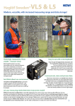
L402 Laser Bluetooth® Hazard Trees Instrument Manual V1.1 English January 2010 Laser L402 V1.1 ©Haglöf Sweden AB L402 LASER INSTRUMENT BLUETOOTH®AND HAZARD TREES FUNCTIONS FOR ACCURATE HEIGHT- DISTANCE AND ANGLE MEASURING IN THE FIELD Art no: 15-103-1011 Laser Class: 1 (USA, Canada) 3A (EU, other countries) Product conforms to all provisions of US21CFR 1040.10 and 1040.11 and IEC 60825-1. For safety instructions and precautions, please see page 19 ff in this manual. Includes: Laser Measuring instrument, soft carrying case and operating manual. Manuals are also available as PDF files for download, and in other languages than English at www.haglofsweden.com. For a paper copy of a manual in selected language, please call or e-mail. Optional Accessories: TRIPOD, art no 15-103-1006, and TRIPOD ADAPTER 15-103-1007 IR receiver for data input in handheld computer or PC Product Origin: Sweden Declaration of conformity according to the EMC Directive 89/336/EEC with amendment 92/31/EEC, Low Voltage Directive 73/23/EEC and CE Marking Directive 93/68/EEC Haglöf Sweden AB Box 28, Klockargatan 8 SE-882 21 Långsele Sweden Ph: +46 620 255 80 Fax: +46 620 205 81 E-mail: [email protected] Haglof Inc., P O Box 2548, 100 Solleftea Drive US-39110 Madison, MS USA Ph: +1 601 856 5119 Fax: +1 601 856 9075 E-mail: [email protected] www.haglofsweden.com 2 Laser L402 V1.1 ©Haglöf Sweden AB Index L402 Laser instrument Bluetooth®and Hazard Trees Functions ............................................................................. 2 For accurate height- distance and angle measuring in the field ........................................................................ 2 The L402 Laser Instrument...................................................................................................................................... 6 General Information: the L402 Laser instrument ............................................................................................... 6 Menu ....................................................................................................................................................................... 7 Setup .................................................................................................................................................................. 8 P.OFFSET ........................................................................................................................................................ 8 REF.HGT ......................................................................................................................................................... 8 M.DIST ........................................................................................................................................................... 9 Select the Distance Unit in the Laser.................................................................................................................. 9 Buttons ............................................................................................................................................................... 9 Shift Button.................................................................................................................................................... 9 Mode Button ................................................................................................................................................. 9 Power Button............................................................................................................................................... 10 Mode + Shift Buttons ................................................................................................................................... 10 Vertex Aim ........................................................................................................................................................ 10 Laser Aim .......................................................................................................................................................... 10 Height Measuring with L402 ................................................................................................................................. 11 Measuring Heights ....................................................................................................................................... 11 Distance and Height Measuring with Laser ...................................................................................................... 12 HEIGHT 3P with Laser ....................................................................................................................................... 12 HEIGHT 2P Laser with Target ............................................................................................................................ 13 HEIGHT 2P Manual Distance ............................................................................................................................ 13 HEIGHT 2P Laser 2-point measuring ................................................................................................................ 14 DELTA HEIGHT .................................................................................................................................................. 14 Delta height function ................................................................................................................................... 15 Instructions .................................................................................................................................................. 15 3 Laser L402 V1.1 ©Haglöf Sweden AB Example ....................................................................................................................................................... 16 Hazard Tree Limit: Function in the L402 to calculate Security Distance ............................................................... 17 General measuring model ................................................................................................................................ 19 TREE LIMIT ........................................................................................................................................................ 20 Manual register of height to power line .......................................................................................................... 20 Measuring height to a power line .................................................................................................................... 21 LASER ........................................................................................................................................................... 21 HEIGHT 1P.................................................................................................................................................... 22 HEIGHT 2P.................................................................................................................................................... 23 Ultra sound (HEIGHT 2P) ............................................................................................................................. 23 Laser (HEIGHT 2P) ........................................................................................................................................ 24 To Measure Tree Heights ...................................................................................................................................... 24 HEIGHT 1P ........................................................................................................................................................ 25 HEIGHT 3P ........................................................................................................................................................ 26 HEIGHT 2P ........................................................................................................................................................ 27 HEIGHT 2PL ....................................................................................................................................................... 28 ANGLE Measuring ............................................................................................................................................. 29 Transfer of Data using IR .................................................................................................................................. 29 Laser L402 V1.1 ..................................................................................................................................................... 30 Bluetooth in common computer units ............................................................................................................. 31 Allegro ......................................................................................................................................................... 31 Recon ........................................................................................................................................................... 31 Data format ...................................................................................................................................................... 32 Height measuring ........................................................................................................................................ 32 Distance measuring ..................................................................................................................................... 32 Sign format Bluetooth ...................................................................................................................................... 32 Battery Indicator in Laser display ..................................................................................................................... 33 Changing the battery ........................................................................................................................................ 33 Battery life ................................................................................................................................................... 33 4 Laser L402 V1.1 ©Haglöf Sweden AB Technical specification .......................................................................................................................................... 34 L402 Laser Instrument ................................................................................................................................. 34 Angle ............................................................................................................................................................ 34 Laser ............................................................................................................................................................ 34 Troubleshooting Laser........................................................................................................................................... 36 SAFETY Information .............................................................................................................................................. 37 Warranty and Service Information ................................................................................................................... 37 SOFTWARE ....................................................................................................................................................... 38 5 Laser L402 V1.1 ©Haglöf Sweden AB THE L402 LASER INSTRUMENT The Laser L402 is a high quality measuring instrument, useful for anyone who needs reliable, fast and accurate distance-, height- or angle- measuring results. The instrument uses the proven accurate and safe measuring methods of laser and a tilt sensor into a small, flexible and unique product. GENERAL INFORMATION: THE L402 LASER INSTRUMENT The L402 Laser instrument uses laser technology to calculate distance and a high quality tilt sensor to measure angles. The laser method can be used with or without the use of the tilt sensor and vice versa. The laser method allows long distance measuring and a quick presentation of measuring results. Data on heights, distances and angles can be transferred through a built-in Infrared transmitter or by Bluetooth® to a PC or HHC, for storage and further processing. For transfer of results, a serial IR receiver for the external device is available as an optional accessory to the L402 instrument. The Laser emits invisible, eye safe infrared energy pulses that reflect off the selected target back to its optical receiver. The laser is classified as Class 1 (USA and Canada) and as Class 3a (EU and other countries). By measuring the time it takes for each pulse to travel from the rangefinder, to the target and back with sophisticated precision charge circuitry, the instrument instantly calculates distances. The maximum range of the Laser measuring method depends on the target’s reflectivity, its colour, surface, finish, shape and size. 6 Laser L402 V1.1 ©Haglöf Sweden AB Power button Mode button 8x magnification Laser aim and Laser display Shift button 1 x magn. Red dot hair cross aim Display IR interface Battery indicator MENU VERTEX LASER HAGLÖF HEIGHT 2P VERTEX LASER CALIBRATE VERTEX LASER VERTEX LASER HAGLÖF HEIGHT 2PL HEIGHT 3P HAGLÖF VERTEX LASER DELTA HGT HAGLÖF VERTEX LASER DISPLAY 7 HAGLÖF VERTEX LASER HAGLÖF ANGLE VERTEX LASER SETUP HAGLÖF HAGLÖF Laser L402 V1.1 ©Haglöf Sweden AB SETUP VERTEX LASER HAGLÖF 1. Press MODE to turn the instrument ON. SETUP 2. Select menu SETUP and press the Mode button. 3. Select distance and height unit. Start the Laser by pressing POWER and select unit as m or Yard by keep pressing the Mode button. The selected unit is featured in the Laser display. Step out of this menu by pressing both SHIFT and MODE. METRIC P.OFFSET REF.HGT M.DIST 4. Select the Angle unit as Deg (degrees), GRAD (gradients) or % (percentage) by pressing SHIFT. Confirm by pressing MODE. DME DIAMETER MEASURING 5. Set the P.OFFSET with SHIFT and MODE. A cursor appears under the digit. Use the Shift button to increase this digit. Confirm the digit by pressing MODE. Repeat for the next digit until the Pivot Offset is set. 6. Set the REF.HGT BAF 20 SET M OR YRD POWER ON AND PRESS (MODE) TO CHANGE P.OFFSET The Pivot Offset is the distance from the Laser instrument front to the virtual intersection point behind the instrument. The normal P.OFFSET is 0.3m/1.0ft. 0.3m REF.HGT Distance to an optional reference point. REF HGT is always added to the height when measuring distance manually. When measuring distance with laser, REF HGT is not used except when using the one-shot method. Then the reference height (REF HGT) should equal your eye height. SD H HD REF.HGT 8 DEG 0.3 1.3 025.0 Laser L402 V1.1 ©Haglöf Sweden AB M.DIST Setting a Manual Distance can be useful if a distance is already known or when the Laser can not be used for distance measuring for certain reasons – if, for example, larger objects cover the target object. NOTE! The accuracy of the entered manual distance affects the height accuracy! SELECT THE DISTANCE UNIT IN THE LASER 1. Press MODE to turn the instrument ON. 2. Select menu SETUP and keep pressing the Mode button until the last screen appears, SET M or YRD. 3. Start the Laser by pressing POWER and select unit as m or Yard by keeping the Mode button pressed. The selected unit is featured in the Laser display. Step out of this menu by pressing both SHIFT and MODE. BUTTONS SHIFT BUTTON The Shift button is used when measuring distances with ultrasound, and to change menus or variables. Shift is also used to increase or decrease the intensity of the Vertex aim. MODE BUTTON The Mode button is used when measuring angles, and works as ENTER, to execute commands in the menu. The Mode button is also used to activate IR transfer of data. Use the Mode button to select the Laser distance setup (English or Metric). To switch unit in the Laser, select SETUP menu and SET M OR YRD (last menu in SETUP). When in this menu, keep the Mode button pressed down to switch between m and Yard. This unit is only used in the Laser display and has no function in the Vertex display, where metric or feet are used. 9 Laser L402 V1.1 ©Haglöf Sweden AB POWER BUTTON Press POWER to start the Laser. To start laser measuring, press again. Keeping the Power button pressed, the Laser performs a scanning measuring operation. This function is useful to obtain the most correct result when measuring thin targets (power lines). The Laser has an automatic turnoff time of 8 seconds of inactivity. MODE + SHIFT BUTTONS Press both Mode and Shift buttons to step out of a menu and to turn the L402 Laser instrument OFF. VERTEX AIM The red dot cross hair aim has a 1 x magnification, with a highly visible red aim point sight. This sight is preferably used for close range targets. The intensity of this aim is user adjustable. Press Shift when measuring a height or an angle to increase intensity of the cross hair. LASER AIM The Laser aim point is often used for distant targets. With an 8 x magnification, the laser aim is perfect for thin objects, for example power lines. The 8 x magnification makes it useful also if a target object is located close to other objects. Adjust the Laser aim sharpness by turning the adjustment ring around the Laser sight until desired sharpness. 10 Laser L402 V1.1 ©Haglöf Sweden AB HEIGHT MEASURING WITH L402 MEASURING HEIGHTS The L402 Laser instrument offers several different measuring methods for accurate height measuring: One shot: Distance and angle to an optional part of the object measured with laser. To be able to work with this method, you need to be on the same level as the bottom of the object to measure. HEIGHT 3P: Distance and angle to optional part of the object measured with laser. The angle is measured at the lowest and the highest part of the object. HEIGHT 2P: Distance and angle, to a reference point, measured with laser. The top angle is measured. HEIGHT 2PL: Distance and angle to the bottom and to the top measured with laser. The method is ideal for leaning objects. Useful and important knowledge: the L402 Laser uses two additional variables when calculating a height. Those variables can be changed in the SETUP menu. P.OFFSET: Distance from the L402 Laser front to the intersection point. REF.HGT: Distance to an optional reference point. When measuring distance with laser, REF HGT is not used except when using the one-shot method. Then the reference height (REF.HGT) should equal your eye height. SD H REF.HGT 11 HD Laser L402 V1.1 ©Haglöf Sweden AB DISTANCE AND HEIGHT MEASURING WITH LASER 1. Press POWER to turn the Laser ON. 2. Aim and press POWER to measure with Laser. The L402 Laser instrument indicates with a short signal when a measuring result has been completed. The display features distance, horizontal distance, angle and height above horizontal plane (REF.HGT included). Press both Mode and Shift buttons to step out of a menu and to turn the Laser instrument OFF. SD Use REF.HGT to add the distance from ground to eye to get the H target’s total height from the ground to the measuring REF.HGT point. HD P. OFFSET should be set to 0.1 m/0.3 ft Objects that are far away or thin (power lines) can be difficult to obtain results from. With the Laser scanning function, activated when pressing the Power button, the best measuring result can be achieved. VERTEX LASER HEIGHT 3P WITH LASER HAGLÖF HEIGHT 3P 1. Press POWER to start the Laser (alternatively, turn the L402 Laser ON by pressing MODE and choose menu HEIGHT 3P) 2. Aim and press POWER to get the distance and angle. Aim until a short beep goes off. The slope distance (SD), the horizontal distance (HD), the height (REF.HGT included) and the angle are featured in the display. SD HD H DEG 21.5 21.4 -1.7 -4.6 BOTTOM DEG -20.8 SD HD DEG H 21.5 21.4 -4.6 19.3 3. Aim at the bottom of the target object or at a reference point. Keep pressing MODE until a beep goes off. Now release the Mode button. 4. Aim at the top of the object and keep Mode pressed until another beep goes off. Now release the Mode button. Height (REF HGT not included) and other data are now featured in the display. More heights on the same target object can be measured by repeating point 4 above. Press both MODE and SHIFT to step out of a menu and to turn the L402 Laser OFF. 12 Laser L402 V1.1 ©Haglöf Sweden AB HEIGHT 2P LASER WITH TARGET VERTEX LASER HAGLÖF HEIGHT 2P 1. Press MODE to turn the instrument ON. M.DIST 25.0 2. Select menu HEIGHT 2P and press the Mode button. DME (MODE) 3. Turn the Laser ON by pressing POWER. LASER (POWER) 4. Aim at the reference point and press POWER to get the distance and angle to the object. Aim until a short beep goes off. Slope distance (SD), horizontal distance (HD) height (REF HGT included) and angle are featured in the display. Release the Mode button. SD HD H DEG 15.0 14.9 -1.9 -7.3 5. Aim at the top of the target object and keep MODE pressed until a beep goes off. Now release the Mode button. SD 15.0 HD 14.9 DEG H -7.3 20.3 Height (REF HGT not included) and other data are featured in the display. More heights on the same target object can be measured by repeating point 5 above. To measure heights of a new target object, repeat from point 4 above, and using the HEIGHT 3P method. HEIGHT 2P MANUAL DISTANCE VERTEX LASER 1. Press MODE to turn the instrument ON. HEIGHT 2P 2. Select menu HEIGHT 2P and press the Mode button. M.DIST 3. Accept the manual distance now shown in the display by a quick press of the Mode button. DME LASER 3. Aim towards the reference point and press Mode to get the correct angle. Aim until a short beep goes off. Now release the Mode button SD HD DEG H 4. Aim at the top of the object and keep Mode pressed until a beep goes off. Now release the Mode button. 25.0 (MODE) (POWER) Height (REF HGT included) and other data can now be seen in the display. More heights on the same object can be measured by repeating point 4 above. Press both MODE and SHIFT to step out of a menu and to turn the L402 Laser OFF. NOTE! The accuracy of the entered manual distance affects the height accuracy! 13 HAGLÖF 25.0 24.6 -10.6 20.1 Laser L402 V1.1 ©Haglöf Sweden AB HEIGHT 2P LASER 2-POINT MEASURING VERTEX LASER 1. Press MODE to turn the instrument ON. HEIGHT 2P 2. Select menu HEIGHT 2P and press the Mode button. SD HD 3. Turn the Laser ON by pressing POWER. H 4. Aim at the bottom of the target (or other reference) and press POWER to get the distance and the angle. Aim until a short beep goes off. HAGLÖF 15.5 DEG -1.4 SD HD 16.0 5. Aim at the top of the target and press POWER to get the distance and angle. Aim until a short beep goes off. H DEG 15.4 Height (REF HGT not included) and other data are now featured in the display. SD SD DEG H 15.5 16.0 13.0 3.7 Press both MODE and SHIFT to step out of a menu and to turn the L402 Laser OFF. VERTEX LASER HAGLÖF DELTA HEIGHT DELTA HGT The Delta Height Function is used to calculate the height difference of a point at an imagined straight line between two fixed positions, and a third point, for example at a power line, where the line sag is closest to the ground. (More details at next page) 1. Go to the position where the line sag is closest to ground. Measure H1 using the 1-point laser method. SD HD 15.5 H DEG -1.4 SD HD 16.0 H 2. Measure H2 using the 1-point laser method 3. Accept H1 and H2 and H by pressing Mode. H is the calculated height to the point above the power line. 4. Measure the height h to the power line using the 1-point laser method. The Delta Height (H-h) is calculated and featured in the display. H1,H2 DEG 15.4 HD HD H8.0 15.5 15.4 H 9.9 H 8.9 H HD HD H 8.0 H Delta H 14 15.5 15.4 H 9.9 0.5 Laser L402 V1.1 ©Haglöf Sweden AB DELTA HEIGHT FUNCTION The Delta Height Function is used to calculate the height difference of a point at an imagined straight line between two fixed positions, and a third point, for example at a power line, where the line sag is closest to the ground. Delta H INSTRUCTIONS The Delta Height Function calculates the difference between two heights. The function REF. HEIGHT in the L402 Laser is therefore not so important in this case. Always stand in a perpendicular position at the point where the Delta Height is measured. OK The Delta Height Function uses the horizontal distances and the heights from the two fixed positions to calculate the height to the point at the (imagined) straight line. If this point is not located in the middle of these two fixed positions, the importance of standing closely increases. OK OK 15 Laser L402 V1.1 ©Haglöf Sweden AB EXAMPLE 1. Go to the position where the line sag is closest to ground. Measure H1 using the 1-point laser method. 2. Measure H2 using the 1-point laser method H2 3. Accept H1 and H2 and H by pressing Mode. H is the calculated height to the point above the power line. h H 4. Measure the height h to the power line using the 1-point laser method. The Delta Height (H-h) is calculated and featured in the display. 16 Laser L402 V1.1 ©Haglöf Sweden AB HAZARD TREE LIMIT: FUNCTION IN THE L402 TO CALCULATE SECURITY DISTANCE The L402 V1.1 includes a useful function to calculate minimum distance from a tree top to, for example, a power line, given the scenario that the tree could fall or be cut down. The function is called TREE LIMIT in the L402. Note that it is recommended to work with a security margin, given that the measurements include uncertain factors that will affect the results. Certain calculations will presume that the object, for example a tree, is standing straight when measuring a height. Trees that are leaning in the opposite direction from the operator’s position will be given a lower height measurement value, with certain functions in the L402. Other factors of 17 Laser L402 V1.1 ©Haglöf Sweden AB uncertainty can affect the power line, such as cold/warm temperature, power output in the line, etc. If you are unsure where the laser beam actually hit when measuring, it is recommended to verify results with at least one more measuring operation. The L402 incorporates several functions for height measuring. Since smaller trees often prevent a free sight to the tree to measure, and also often prevent supplementary tree base measuring, the HEIGHT 1P function (one measuring, aiming at the tree top) is often used. The L402 will, in such cases, presume that the tree base is leveled with the ground. Note that, in cases where the tree base/root is lower than ground level, a larger safety and security margin is necessary, since the tree height otherwise will be underestimated. Below pictures show a tree and a power line. With a number of measurements with the L402, the instrument can calculate the distance featured in picture 2. If this distance is small or negative, the tree top can reach the power line if felled. The function can also be used to calculate security distance as in picture 3. Bild 1 Picture 3 Picture 2 18 Laser L402 V1.1 ©Haglöf Sweden AB GENERAL MEASURING MODEL The minimum distance to the power line is measured in two steps: 1. Measure or state the height to the power line (or other object). 2. Stand under the power line. Measure the tree height. The tree height and its position relative to the power line are registered and the minimum distance from the top to the power line is calculated. DELTA HGT HEIGHT 2P HEIGHT 3P ANGLE SETUP CONTRAST BLUETOOTH CALIBRATE HEIGHT 2PL CODE 12345 CODE 12345 BLUETOOTH ON 19 Laser L402 V1.1 ©Haglöf Sweden AB TREE LIMIT Go to the SETUP menu and make sure that the P.OFFSET is correctly set (app. 0.3m) and that the EYE HGT is set as the distance from ground level to your eyes, usually app. 1.7m. If the ultra sound transponder needs to be used (in dense vegetation) check also that the TRP.HGT is correct in the L402, normal setting 1.3m (breast height). Start the L402 by pressing MODE and go to menu TREE LIMIT. Press MODE. You can now choose if to state the power line height manually or if to measure it. TREE LIMIT MANUAL REGISTER OF HEIGHT TO POWER LINE If the height to the power line is known, choose method MANUAL in the menu OBJECT HGT and press MODE. OBJECT HGT MANUAL State the known height in meters by stepping up/down using the DME button. Proceed to the next digit with MODE. State the height as 00.0 if you wish to know where the top will touch ground in relation to your position when cutting the tree. OBJECT HGT Press MODE when the last digit has been input to continue measuring tree height, see this manual. 20 10.0 Laser L402 V1.1 ©Haglöf Sweden AB MEASURING HEIGHT TO A POWER LINE When the height to the power line is not known, it needs to be measured. This is done in the function MEAS in the OBJECT HGT menu. Choose the function MEAS with the DME button and press MODE. There are three methods to calculate correct height to the power line. TREE LIMIT OBJECT HGT Laser measuring up to power line. LASER MEAS HEIGHT 1P Height calculation with laser measuring and one angle. HEIGHT 2P Height calculation with laser and two angles. LASER Method to use only if you are positioned with the L402 at least 10m/32ft from the power line. 1. 2. 3. 4. 5. 6. Stand just under the power line. Make sure that no objects are above the power line that you intend to measure with the laser, to avoid hitting something else with the laser beam. Choose LASER method with the DME button. Press MODE. Stand under the power line, start the laser in L402 with one press at the POWER button. Aim at the line and press POWER to measure the distance up to the power line. The EYE REF distance will automatically be added to the measuring result. Repeat point 4 if needed. Accept the height result by pressing MODE and to move on to measure tree heights, see this manual. OBJECT HGT METHOD LASER LASER AIM AND PRESS POWER TO MEASURE HEIGHT 16.2M 21 Laser L402 V1.1 ©Haglöf Sweden AB HEIGHT 1P The Height 1P method is used to measure the height to the power line when you are positioned on a distance from the line. The minimum distance between the VL402 to the power line is 10m/32ft. 1. 2. 3. 4. 5. Stand at ground level under the power line. Make sure that no objects are above the line you intend to measure, to avoid hitting something else with the laser beam. If you accidentally hit another line or object, your measuring result will be incorrect! Choose HEIGHT 1P method with the DME button. Press MODE. Start the laser in L402 by pressing the POWER button. Aim at the power line and press POWER to measure the distance and the angle to the line. Proceed aiming until the angle ready measured, and you hear a signal. The height is now calculated and the EYE REF distance automatically added. Repeat point 4 if needed. Accept the height with a press at MODE. To proceed to measure tree heights, see this manual for instructions. OBJECT HGT METHOD HEIGHT 1P SD 12.3 HD 5.0 H DEG 22 10.5 50.3 Laser L402 V1.1 ©Haglöf Sweden AB HEIGHT 2P With HEIGHT 2P you can measure the height by using two measuring points. You will not need to be positioned at ground level under the power line. The laser or the ultrasound can be used to measure the distance to a point at the ground under the power line. Ultrasound can be used when it is difficult to find a good measuring point with the laser due to thick and dense vegetation. ULTRA SOUND (HEIGHT 2P) 1. 2. 3. 4. 5. 6. 7. Start the ultra sound T3 transponder. Place the transponder under the power line. Make sure that the correct TRP.HGT (transponder height) in the SETUP menu is used for the occasion. The TRP.HGT can be set at any height, for example 0.0m or 1.3m if used with the plot staff and adapter. Choose HEIGHT 2P with the DME button. Press MODE. Aim at the transponder and press MODE button and keep it pressed until a signal is heard. Release the MODE button. Aim at the power line and press MODE until you hear a signal. The height is calculated and shown in the display. Accept the measured height with one press at MODE and to proceed measuring tree heights, see this manual. OBJECT HGT METHOD HEIGHT 2P M.DIST DME (MODE) LASER (POWER) 23 Laser L402 V1.1 ©Haglöf Sweden AB OBJECT HGT LASER (HEIGHT 2P) 1. 2. 3. 4. 5. 6. Choose HEIGHT 2P with the DME button. Press MODE. Start the laser with a press at POWER. Aim at the power line and press POWER to measure the distance and angle to the line. Make sure that no objects are positioned above the line that you intend to measure. Proceed aiming at the power line until the angle is measured and a signal Is heard. Repeat point 3 if needed. Measure the angle to a point under the power line. It is preferable to mark this point prior to the measuring, since it is difficult to estimate where it is. Aim and keep the MODE button depressed, and until you hear a signal. Heights are calculated and shown in the display. Accept the height with a press at MODE and to proceed to measure tree heights, see the manual. METHOD HEIGHT 2P M.DIST DME (MODE) LASER (POWER) TO MEASURE TREE HEIGHTS SD 12.3 After having registered the distance to the power line, proceed to measure tree heights. Tree heights are measured by standing in perpendicular position under the line facing the tree. The VL402 offer four different methods to calculate tree heights. Depending on where the tree is standing and in type of environment and terrain, you can choose appropriate method: HD 5.0 DEG 50.3 HEIGHT 1P Laser measuring and tree top angle. HEIGHT 3P Laser measuring at tree stem and angle at tree top and base HEIGHT 2P Laser measuring and angle at tree top and base. HEIGHT2PL Laser measuring and angle to tree top and base. 24 H1 10.5 Laser L402 V1.1 ©Haglöf Sweden AB HEIGHT 1P If the tree base is equal to ground level underneath the power line, one measuring operation is enough to calculate the height. 1. 2. 3. 4. 5. 6. 7. 8. Stand under the power line. Choose HEIGHT 1P with the DME button. Press MODE. Start the L402 laser with a press at the POWER button. Aim at the tree top and press POWER to measure this distance. Continue aiming at the top until the angle has been measured and you can hear a signal. The EYE REF distance is automatically added to the calculated height. Repeat point 4 if needed. Press MODE to accept the result. The VL402 will calculate the minimum theoretical distance between the top and the power line. If this result is negative (NOT OK) the tree may hit the power line if felled. Press MODE to proceed to measure the next tree. TREE HGT METHOD NOT OK OK DIFF. DIFF. -1.0M 5.0M HEIGHT 1P SD 22.3 HD 15.0 H DEG 25 20.5 35.3 Laser L402 V1.1 ©Haglöf Sweden AB HEIGHT 3P Height 3P measuring is best used when the tree base is visible and not leveled with the ground under the power line. 1. 2. 3. 4. 5. 6. 7. 8. 9. Stand under the power line. Choose HEIGHT 3P with the DME button and press MODE. Start the VL402 laser with a press at the POWER button. Aim at any point on the stem and press POWER to measure the distance and angle. Continue aiming. When the angle is ready measured, you will hear a signal. Aim at the tree base and measure the angle by pressing the MODE button and keeping it depressed until you hear a signal. Release MODE. Aim at the tree top and measure the angle by pressing the MODE button and keeping it depressed until you hear a signal. Release MODE. Press the MODE button to accept the measuring results. The L402 calculates the minimum theoretical distance between the tree top and the power line. If the result is negative (NOT OK) the tree may hit the power line if felled. TREE HGT METHOD HEIGHT 3P SD 22.3 HD 15.0 H Press MODE to proceed to measure the next tree. DEG 26 NOT OK OK DIFF. DIFF. -1.0M 5.0M 20.5 35.3 Laser L402 V1.1 ©Haglöf Sweden AB HEIGHT 2P When the vegetation is dense and the tree base is difficult to spot, it is recommended to use the HEIGHT2P measuring method. Preferably work with the ultrasound transponder, also if laser measuring is possible. 1. 2. 3. 4. 5. 6. 7. 8. 9. Start the T3 ultra sound transponder. Pin the transponder to the tree stem. Make sure that the TRP.HGT in the SETUP menu is correctly set at the height where the T3 transponder actually is placed, for example at 1.3m (normal breast height). Choose HEIGHT 2P with the DME button. Press MODE. Stand under the power line and aim at the T3 transponder, press MODE and keep MODE depressed until you hear a signal. Release MODE. Aim at the tree top and press MODE until you hear a signal. The height is calculated and shown in the display. Press MODE to accept the measuring result. The VL402 calculates the minimum theoretical between the tree top and the power line. If the result is negative (NOT OK) the tree may it the power line if felled. Press MODE to proceed to measure the next tree. OBJECT HGT METHOD HEIGHT 2P M.DIST DME (MODE) LASER (POWER) NOT OK OK DIFF. DIFF. -1.0M 5.0M 27 Laser L402 V1.1 ©Haglöf Sweden AB HEIGHT 2PL The HEIGHT 2PL method is recommended to use for leaning trees. The angle and distance to the tree top and tree base are measured. 1. 2. 3. 4. 5. 6. 7. 8. Stand under the power line. Choose HEIGHT 2PL with the DME button. Press MODE. Start the L402 laser with the POWER button. Aim at the tree base and press POWER to measure the distance. Continue aiming until angle measuring is ready and you hear a signal. Aim at the tree top and press POWER to measure the distance. Continue to aim until the angle measuring is ready and you hear a signal. Press MODE to accept the measuring result. The L402 will calculate the minimum theoretical distance between the tree top and the power line. If the result is negative (NOT OK) the tree may hit the power line if felled. Press MODE to proceed to the next tree. OBJECT HGT METHOD HEIGHT 2P NOT OK DIFF. -1.0M SD 22.3 HD 15.0 H 20.5 DEG 28 35.3 Laser L402 V1.1 ©Haglöf Sweden AB ANGLE MEASURING VERTEX LASER HAGLÖF 1. Press MODE to turn the instrument ON. ANGLE 2. Select menu ANGLE and press MODE. 3. Aim and keep MODE until a beep goes off. Release the Mode button. DEG The angle is now featured in the display. Press both MODE and SHIFT to step out of a menu and to turn the L402 Laser OFF. TRANSFER OF DATA USING IR The IR transfer can be activated in any measuring mode. Just press the Mode button once. Data format '1 NNNN' Height 1 (the 2 (two) last measured heights are transferred) '2 NNNN' Height 2 '3 NNNN' not used '4 NNNN' H-Dist 5 ANNN' Angle A='+','-' (gradients) Baud=1200,7 bit Data, Even Parity 29 15.4 Laser L402 V1.1 ©Haglöf Sweden AB LASER L402 V1.1 This section is only valid for Vertex Laser model VL402 or Laser L402 with built-in Bluetooth®. VL402 BT V1.0 DME, DELTA, Bluetooth VL402 V1.0 DME, DELTA L402 BT V1.0 DELTA, Bluetooth L402 V1.0 DELTA VL402 and L402 can send wireless data to handheld computer or PC with Bluetooth. The connection is made when the instrument is in slave-mode. Certain computers require an activated pin code to connect. The code should be activated in menu BLUETOOTH. The VL402/L402 uses the following pin code: 12345. Use this code if the function for pin code is activated. To activate Bluetooth in the VL402/L402 select menu BLUETOOTH. Activate pin code if necessary (see above) and set menu choice ’—’ to ’ON’ using the arrow keys. An external device can now connect to the VL402/L402. DELTA HGT HEIGHT 2P HEIGHT 3P ANGLE SETUP CONTRAST BLUETOOTH CALIBRATE HEIGHT 2PL Data of measuring result is sent with a short press on the Mode key after having measured (height, angle or distance). CODE 12345 The VL402/L402 is set to disconnect the Bluetooth function 20 minutes after having turned off the instrument VL402/L402. Note that the VL402/L402 will consume more battery with the Bluetooth function activated. To save battery, it is recommended to manually turn off the Bluetooth function when not in use. Deactivate Bluetooth by changing ’ON’ back to ’—’ in the BLUETOOTH menu. CODE 12345 BLUETOOTH ON 30 Laser L402 V1.1 ©Haglöf Sweden AB If the Bluetooth function is active and the VL402/L402 instrument has been turned off, a message appears in the instrument display telling that the Bluetooth is running. Make sure that the distance between the external, connected unit and the VL402/L402 does not exceed 10 m/32ft which is the maximum distance for data transfer. BLUETOOTH IN COMMON COMPUTER UNITS NOTE Documentation can often limited on which ports in a computer unit that is dedicated for the Bluetooth function. The operator may have to try his way through. Below are examples of ports in some common handheld units: IS TURNED OFF AFTER 20 MINUTES ALLEGRO The COM6 is usually the internal Bluetooth port RECON The COM4 is usually the internal Bluetooth port 31 Laser L402 V1.1 ©Haglöf Sweden AB DATA FORMAT Data from the VL402/L402 is sent serial as text according to the below: Data packet containing a total of 40 signs. 1 0000 [LF][EOL] 2 0000 [LF][EOL] 3 0000 [LF][EOL] 4 0000 [LF][EOL] 5 +000 [LF][EOL] (At negative angle ‘+’ inserted with ‘-‘) LF=Linefeed (ASCII 13) EOL=End of line (ASCII 10) HEIGHT MEASURING Line 1: 1:a height (dm alt. feet X 10) Line 2: 2:a height (dm alt. feet X 10) Line 3: 3:a height (dm alt. feet X 10) Line 4: Horizontal distance to object (dm x 10 alt. ft X10) Line 5: Angle to object (grades X10) DISTANCE MEASURING Line 1: Distance to transponder (cm alt feet X 10) Line 2: 0000 Line 3: 0000 Line 4: 0000 Line 5: Angle to object (grades X10) *If the angle (line 5) has a value larger or less than zero (0), the distance will be the calculated horizontal distance. SIGN FORMAT BLUETOOTH The transfer speed and number of stop bits are set automatically by the receiver. Number of bits per sign are 8 data bits and no parity. 32 Laser L402 V1.1 ©Haglöf Sweden AB BATTERY INDICATOR IN LASER DISPLAY Battery has enough power for use. Battery power is getting low. Battery power is low, image of battery is flashing and battery should be replaced. CHANGING THE BATTERY 1. Open the battery chamber cover using a coin or similar and rotate it following the “Open/Close” indication. Due to the water and dust-resistance seal, it may not open easily. 2. Install the new battery with the [+] and [-] correctly positioned. 3. Screw the cover back in place using a coin or similar. Confirm the cover to be correctly closed. BATTERY LIFE A new battery should last approximately 3000 measurements at 20º C/70F. The figure may differ according to temperature, target shape etc. The automatic turn-off function ensures longest possible life for the battery. The turn-off time is set to approximately 8 seconds for the Laser unit. 33 Laser L402 V1.1 ©Haglöf Sweden AB TECHNICAL SPECIFICATION L402 LASER INSTRUMENT Size Weight Battery Power consumption Temperature range Height Resolution height (display) Meter / Feet Buzzer 95 x 72 x 58 mm / 3.7” x 2.8” x 2.3” 260 g / 9 oz (battery included) 1 x CR 2 Lithium 3V 60mW -15° to +45°C / 5F to 113F 0-999 m/ft 0.1m/ft Yes Yes ANGLE Angle range Deg / Grad / % Resolution angle Accuracy Red dot aim -55 to +85deg Yes 0.1deg 0.1deg Aim point; 1x magnification LASER Laser Class Distance non-reflective target Distance reflective target Resolution (display) Accuracy Rain mode Number of measurements Laser aim ZipThru >140m/yards (filter) Scan (continuous measuring) Meter / Yards FDA Class 1/EN60825-1 Class 3A Max. 350m/400yard (aut.setup reflect/nonreflect target) From 130m to 900m / 150yard to 999yard 0.5m/yard at distance <100m/yard, else 1m/yard ±0.4m/yard at distance <100m/yard, else ±1m/yard Yes, automatic approx. 3000 Reticule; 8 x magnification Yes Yes Yes Data transfer Built in IR, built-in Bluetooth® class 2, Pin Code 12345 34 Laser L402 V1.1 ©Haglöf Sweden AB SAFETY AND OPERATION PRECAUTIONS To avoid injury or material loss, please read this safety and operation precautions thoroughly: • • • • • • • • • • Never look directly at the laser beam or directly at the sun when using the L402 Laser instrument. Do no use the L402 Laser instrument together with other optical instruments, such as binoculars and lenses. Using an optical instrument together with the L402 Laser increases the danger of eye damage. Do not depress the POWER button while aiming with the eye or looking into the optics from the objective side. Do not disassemble the L402 Laser instrument. Any signs of disassembling automatically withdraw any warranties and the manufacturer does not guarantee the product. If the L402 Laser instrument body cover is damaged, or if the instrument emits a strange sound due to dropping, remove the battery and stop using immediately. Never place the L402 Laser in an unstable place. Never look through the L402 Laser instrument while walking. If you should develop any symptoms of eye irritation or skin inflammation around the eye due to use of the rubber eyecup, consult a doctor immediately. If the L402 Laser instrument should fail to operate correctly, discontinue use and consult the manual. If you are unable to fix the problem, contact your local dealer for instructions or where to send the instrument for repair. The L402 instrument has built-in Bluetooth® for data transfer to external devices. There may be local restriction on the use of both Bluetooth® and laser technology. It is the operator’s responsibility to control that the technology in the instrument is permitted to use in the area where the instrument is operated. CARE, STORAGE AND MAINTENANCE • Store the L402 Laser in its soft case when carrying. Do not swing the instrument by its strap. • Although the L402 Laser instrument is water and dust resistant, it should not be used in water and it is not waterproof. • Use a soft, clean and dry cloth to clean the L402 Laser instrument if exposed to rain, water, sand and mud. Do not use alcohol, benzene, thinner or other organic agents to clean the instrument’s main body! Always clean as soon as possible after the exposure, and always store the instrument in a dry, cool place and away from direct sunlight. • Use a soft oil-free brush to remove dust from the lens surface. To remove stains or smudges (fingerprints etc), wipe lenses gently with a soft clean cotton cloth or oil-free lens tissue. Stubborn smudges can be removed with a small amount of pure alcohol using extra care to avoid scratching of the lens surface. The tissue should only be used one time. • Do not expose the instrument to excessive heat or ultraviolet rays, since this may negatively affect or damage the unit. • Avoid pushing the POWER button when not using the L402 Laser instrument. • When exposed to sudden changes in temperature or high humidity, water condensation may appear on lens surfaces. Do not use the L402 Laser instrument until this condensation has evaporated. Dry the instrument at room temperature and store in a cool, dry place. • Keep the instrument and any parts of and for the instrument out of reach of small children. Consult a doctor immediately if a small child has swallowed any parts of the instrument or its packing. NOTES ON BATTERIES • Batteries should always be removed when exhausted or during longer periods of non-use. • Make sure that batteries are installed correctly in their + and – position. • Rinse skin or eyes well with water if exposed to battery fluid. If swallowed, contact a doctor • Do not short-circuit battery chamber terminals, and do not carry batteries with keys or coins in a pocket. This may short-circuit the batteries. • Keep away from fire and water and do not disassemble batteries. • Do not attempt to charge batteries. Avoid strong vibrations, shock or extremes in temperatures for stored batteries. • If handled incorrectly, batteries may rupture and leak, corroding equipment and staining clothing 35 Laser L402 V1.1 ©Haglöf Sweden AB TROUBLESHOOTING LASER Symptom Laser does not turn on/ Display fails to illuminate Target range cannot be obtained [---] appears Close targets cannot be measured Targets beyond a certain distance cannot be measured Measurement results are unstable Incorrect results are displayed Check points Depress POWER button Check and replace battery if necessary Make sure that nothing is blocking the laser emission aperture and laser detector. Make sure that the laser emission aperture and detector is clean. Clean if necessary (see page 17, Care, storage and maintenance). Target shape and condition may be inappropriate to reflect the laser beam. Slender targets, targets with small reflecting surface, targets with diffusing reflective surface, targets that do not reflect the laser beam, targets with pronounced depths, targets measured through glass and weather conditions such as snow, rain or fog can affect the measuring. Replace battery if necessary. Hold unit steady while pressing the POWER button. Make sure the target is within the measuring range (10m/10.5yds – 400m/437yds) Be sure that nothing is blocking the target Be sure that nothing is blocking the target Replace battery Be sure that target shape and condition can reflect the laser beam. Hold the unit steady while pressing the POWER button Be sure that nothing is blocking the target Replace battery Be sure that target shape and condition can reflect the laser beam. Be sure that nothing is blocking the target Haglöf Sweden AB, 2010 36 Laser L402 V1.1 ©Haglöf Sweden AB SAFETY INFORMATION Laser 400/L402 USA: 21CFR 1040.10, 1040.11 FCC Part 15 Class B; EU EN60825-1:1994 + all EU EMC directive Type of equipment Distance and angle meter Brand name or trade mark Vertex Laser Manufacturer’s name, address, telephone & fax no Haglöf Sweden AB, Klockargatan 8, SE-882 21 Långsele, Sweden Tel: +46 620-25585, Fax: +46 620-20581, [email protected]; www.haglofsweden.com The Vertex was CE marked 1999 WARRANTY AND SERVICE INFORMATION Haglöf Sweden AB warrants that this product shall be free from defects in materials and workmanship, under normal intended use, for a period of 12 months after date of shipment. The warranty excludes the batteries, the accessories and any written materials. The warranty does not apply if the product has been improperly installed, improperly calibrated or operated in a manner not in accordance with the user’s guide. Warranty is also automatically expired if the product has been opposed to external force and warranty is not applicable for cosmetic defects. The one-year limited warranty time covers obvious fabrication defects. Defects in the electronic components that are impossible for the manufacturer to detect prior to assembling and shipping of the product may occur. Haglöf Sweden AB can in no case be responsible for problems of this nature and has no liability for any loss of business, profits, savings, consequential damages or other damages resulting from use of the products described. Signs of misuse, cosmetic damage, accidents or equal automatically withdraw the warranty. The warranty is valid in the country where your Haglöf product has been purchased. A product covered by warranty will be object to exchange, service, and repair or according to special agreement between seller and buyer, within the frames of the limited warranty. Haglöf Sweden reserves the right to determine which option will be most suitable for each separate case after having examined and evaluated the product. 37 Laser L402 V1.1 ©Haglöf Sweden AB IMPORTANT ISSUES: • • • • • For a valid warranty, a copy of invoice or dated receipt of your purchase must be presented. The serial number of the returned product has to be clearly stated upon return. Go to http://www.haglofsweden.com/PDF/HaglofRMA.pdf for return form/turn to your supplier for assistance. The return freight to us is on buyer’s expense. After warranty repair or exchange, the return freight to you is on our expense. If warranty has expired or is null and void, all freights are on buyer’s expense. If no original invoice can be presented upon shipment, or if two years or more have passed from date of purchase, a customs fee will be added by the applicable customs authorities and possibly in receiving country as well. These fees are on buyers account. We perform repair and service of products where warranty has expired when possible. Cost estimation will be sent to you after evaluating the returned product for cost approval. Please also see above paragraph on customs fees. Please do not hesitate to contact us or any Haglöf Sweden AB representative for questions or comments! Any signs of misuse or negligence automatically withdraw our warranty commitments SOFTWARE © Copyrights of Haglöf Sweden AB Software belong to Haglöf Sweden AB. Unauthorized duplication is prohibited. Haglöf Sweden AB is registered trademark and VERTEX is a recognized trademark of Haglöf Sweden AB. Production is made in Sweden. Haglöf Sweden and its suppliers cannot warrant the performance or results when using the firmware, software or hardware, nor the documentation. No warranties or conditions are made; neither expressed nor implied, of merchantability, suitability or special fitness for any particular purpose. If software problems appear, please contact your programmer for support. Haglöf Sweden takes no responsibility for loss of income, time, or problems and delays due to problems in soft- or hardware of products. *Copyrights of all software & firmware made by Haglöf Sweden belong to Haglöf Sweden* Any lists and/or information of software for any Haglöf Sweden AB products should be considered as brief descriptions and not as a complete guide to what may and may not be available. For further details, please see ORGALIME SW01, General Conditions for Computer Software, and Supplement to ORGALIME S 2000 or ORGALIME SE 94. 38