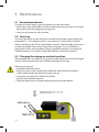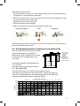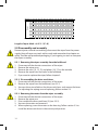
1
Cat. nos. 211255.35/211255.65 (12V) - 212455.35/212455.65 (24V)
Exalto windshield wiper
Type: 255BS
Quality Marine Equipment
Safety
Exalto windshield wipers are easy to install, yet a fair amount of technical
knowledge (mechanical and electrical) is required of the installer. Please
consult the manual or contact your vendor in case of doubt during installation
or malfunctioning.
Safety symbols
An exclamation mark in front of the text warns you, that injury or damage can
occur if a procedure is badly performed.
! Dangers
The installation and use of Exalto wipers will not inflict any personal dangers or
damage, provided that installation is done according to the procedures
specified in the manual.
• Never remove covers or other safety provisions, unless maintenance is being
performed and all safety requirements are obeyed.
• The installer must provide all necessary covers.
• Always disconnect the electrical circuit when performing maintenance.
Prevent the installation from being started (accidentally) by others.
! Safety provisions
The safety provisions will protect the user against contact with moving,
electrical or hot parts. Some of them have to be provided by the installer.
There are several safety provisions:
• This wiper comes complete with a built-on cover. It prevents users from direct
contact with moving parts of the motor. Never remove this safety provision.
• Make sure the wiper has enough ventilation when placing it behind a panel
or cover.
• Place a fuse (see specifications) in the main cable.
Safety requirements
Before the Exalto wiper is installed, we strongly recommend the following:
• Read the entire manual before installation.
• Make sure your working environment as well as the wiper parts are clean.
• Check to be sure no parts are missing or damaged.
• Use only high quality tools and have them within reach when installing.
• Handle the parts with care.
2
• Never install or maintain the wiper with the electrical voltage applied, unless
this is specifically mentioned in the manual.
• Clear your tools after installation.
Use of the manual
Read the entire manual before installation. In this manual you can find the
following expressions and symbols:
! Hint!
Gives you advice on how to perform a task more easily.
Attention!
Alerts you to possible problems and safety warnings.
3
Contents
1Introduction . . . . . . . . . . . . . . . . . . . . . . . . . . . . . . . . . . . . . . . . . . . . . . . . . . . . . . . . . . .
1.1 Introduction . . . . . . . . . . . . . . . . . . . . . . . . . . . . . . . . . . . . . . . . . . . . . . . . . . . . . . .
1.2 Environmental factors . . . . . . . . . . . . . . . . . . . . . . . . . . . . . . . . . . . . . . . . . . . . . .
1.3 Modified use and guarantee conditions . . . . . . . . . . . . . . . . . . . . . . . . . . . .
5
5
5
5
2 Technical data . . . . . . . . . . . . . . . . . . . . . . . . . . . . . . . . . . . . . . . . . . . . . . . . . . . . . . . . . .
2.1General . . . . . . . . . . . . . . . . . . . . . . . . . . . . . . . . . . . . . . . . . . . . . . . . . . . . . . . . . . . .
2.2 Electrical data 12 and 24 Volt . . . . . . . . . . . . . . . . . . . . . . . . . . . . . . . . . . . . . . .
2.3 Mechanical data . . . . . . . . . . . . . . . . . . . . . . . . . . . . . . . . . . . . . . . . . . . . . . . . . . .
6
6
6
6
3Installation . . . . . . . . . . . . . . . . . . . . . . . . . . . . . . . . . . . . . . . . . . . . . . . . . . . . . . . . . . . . .
3.1Preparation . . . . . . . . . . . . . . . . . . . . . . . . . . . . . . . . . . . . . . . . . . . . . . . . . . . . . . . .
3.2 Installation of mechanical parts . . . . . . . . . . . . . . . . . . . . . . . . . . . . . . . . . . . .
3.3 Electrical installation . . . . . . . . . . . . . . . . . . . . . . . . . . . . . . . . . . . . . . . . . . . . . . .
3.4 Final installation . . . . . . . . . . . . . . . . . . . . . . . . . . . . . . . . . . . . . . . . . . . . . . . . . . .
7
7
7
8
9
4 Operation and use . . . . . . . . . . . . . . . . . . . . . . . . . . . . . . . . . . . . . . . . . . . . . . . . . . . . 11
4.1 Preparation for first use . . . . . . . . . . . . . . . . . . . . . . . . . . . . . . . . . . . . . . . . . . . 11
4.2 Use . . . . . . . . . . . . . . . . . . . . . . . . . . . . . . . . . . . . . . . . . . . . . . . . . . . . . . . . . . . . . . . 11
5Maintenance . . . . . . . . . . . . . . . . . . . . . . . . . . . . . . . . . . . . . . . . . . . . . . . . . . . . . . . . . . 12
5.1 General maintenance . . . . . . . . . . . . . . . . . . . . . . . . . . . . . . . . . . . . . . . . . . . . . 12
5.2Servicing . . . . . . . . . . . . . . . . . . . . . . . . . . . . . . . . . . . . . . . . . . . . . . . . . . . . . . . . . 12
5.3 Changing the wipe arc and park position . . . . . . . . . . . . . . . . . . . . . . . . . . 12
5.4 Rough determination of wipe arc and wiper blade . . . . . . . . . . . . . . . . . 13
5.5 Disassembly and assembly . . . . . . . . . . . . . . . . . . . . . . . . . . . . . . . . . . . . . . . . 14
6Troubleshooting . . . . . . . . . . . . . . . . . . . . . . . . . . . . . . . . . . . . . . . . . . . . . . . . . . . . . . 15
7 Declaration of conformity . . . . . . . . . . . . . . . . . . . . . . . . . . . . . . . . . . . . . . . . . . . . . 16
8 Parts list . . . . . . . . . . . . . . . . . . . . . . . . . . . . . . . . . . . . . . . . . . . . . . . . . . . . . . . . . . . . . . . 17
9 Drawings and schemes . . . . . . . . . . . . . . . . . . . . . . . . . . . . . . . . . . . . . . . . . . . . . . . . 18
9.1 Assembly overview . . . . . . . . . . . . . . . . . . . . . . . . . . . . . . . . . . . . . . . . . . . . . . . 18
9.2 Internal wiring diagram . . . . . . . . . . . . . . . . . . . . . . . . . . . . . . . . . . . . . . . . . . . 19
4
1 Introduction
With this user manual we want to guide
you thru the installation and use of the
Exalto windshield wiper. Please follow all
instructions and install all safety
provisions.
1.1 Introduction
The Exalto windshield wipers are
especially designed to keep working even
with the most extreme weather conditions
at sea.
All external parts are made of corrosion resistant materials. The housing of the
self-lubricating bearings is made of bronze. All arms and blades have a black,
weather-resistant coating, to prevent reflection of the sunlight.
Wiper type 255BS is designed to be mounted in the bulkhead or in the glass
window. The wiper arc is stepless adjustable from 40° to 90°. Standard the
255BS is supplied for a bulkhead thickness of 35mm and 65mm. The
pantograph arms have adjustable lengths; between 750mm and 1000mm. The
motor of the 255BS has insulated earth return.
1.2 Environmental factors
Inthewiper,materialsareusedthatareharmfulfortheenvironment
(e.g.copper).Thepartsofthewipercanbere-usedorrecycled.Noharmful
substances are disseminated when using or disassembling the wiper.
1.3 Modified use and guarantee conditions
All modifications or defects in the product are subject to the Orgalime General
Conditions of Sale. Please contact your vendor in case of any questions or if you
want to use Exalto wipers in a non-maritime environment or other applications.
5
2 Technical data
2.1General
• Product . . . . . . . . . . . . . . . . . . . . . . .
• Type . . . . . . . . . . . . . . . . . . . . . . . . . . .
• Catalogue numbers . . . . . . . . . . . .
. . . . . . . . . . . . . . . . . . . . . . . . . . . . .
2.2 Electrical data 12 Volt
• Torque (max.) . . . . . . . . . . . . . . . . . .
• Voltage . . . . . . . . . . . . . . . . . . . . . . . .
• Current . . . . . . . . . . . . . . . . . . . . . . . .
• Power consumption (max.) . . . . .
• Number of revolutions . . . . . . . . .
• Recommended cable . . . . . . . . . .
. . . . . . . . . . . . . . . . . . . . . . . . . . . . .
• Recommended fuse . . . . . . . . . . .
• Grounding . . . . . . . . . . . . . . . . . . . . .
Electrical data 24 Volt
• Torque (max.) . . . . . . . . . . . . . . . . . .
• Voltage . . . . . . . . . . . . . . . . . . . . . . . .
• Current . . . . . . . . . . . . . . . . . . . . . . . .
• Power consumption (max.) . . . . .
• Number of revolutions . . . . . . . . .
• Recommended cable . . . . . . . . . .
. . . . . . . . . . . . . . . . . . . . . . . . . . . . .
• Recommended fuse . . . . . . . . . . .
• Grounding . . . . . . . . . . . . . . . . . . . . .
2.3 Mechanical data
• Dimensions . . . . . . . . . . . . . . . . . . . .
• Bearing diameters . . . . . . . . . . . . .
• Mounting . . . . . . . . . . . . . . . . . . . . .
• Bearing . . . . . . . . . . . . . . . . . . . . . . . .
• Wiperarms . . . . . . . . . . . . . . . . . . . . .
• Wiperblades . . . . . . . . . . . . . . . . . . .
• Wipe arc . . . . . . . . . . . . . . . . . . . . . . .
• Number of revolutions . . . . . . . . .
• Weight . . . . . . . . . . . . . . . . . . . . . . . .
6
Exalto windshield wiper
255BS
211255.35 211255.65(12V)
212455.35 212455.65(24V)
55 Nm
12 Volt
7A
84 W
Low 38 rpm, high 60 rpm
5 wires, 1½ (16 g) or 2½ mm² (14 g)
up to 10 m long
8 A slow blow
Insulated earth return
55 Nm
24 Volt
4A
96 W
Low 38 rpm, high 60 rpm
5 wires, 1½ (16 g) or 2½ mm² (14 g)
up to 10 m long
6 A slow blow
Insulated earth return
L x w x h = 250 x 126,7 x 126 mm
Drive shaft Ø 20 / support shaft Ø 20 mm
Through glass or bulkhead
Bronze housing, self-lubricating
Model P10 up to 1000 mm
Up to 1200 mm
Wipe arc slot 40°-90°,stepless adjustable
Low 38 rpm, high 60 rpm
Approx. 4,80 kg
3Installation
Read the chapter on safety. Check before installation if the parts are all present
and undamaged. In case of errors, contact your vendor.
3.1Preparation
The complete wiper, with packaging, can be handled and transported by hand.
Leave the wiper in the packing, until you are ready to install it; this to reduce
the risk of damage. Make sure all parts, tools and other means are ready.
3.2 Installation of mechanical parts
1.The wipe arc of your wiper is not set. Please follow steps described in
paragraphs 5.3 and 5.4 to set the wiping arc prior to installation.
Determine the place where the wiper is to be installed. The dimensions are
shown below. The wiper can be installed in any position.
7
! Attention!
When installing the wiper, reserve space for a housing or cover.
!
2.Place the windshield wiper in the pre-drilled holes of the bulkhead (see
figure). A rubber sealing plate must be placed at both sides of the
bulkhead.
Attention!
Do not fit the wiper arm before finishing the electrical connections.
3.3Electrical installation
3. Install a wiper switch in the dashboard.
Wiring diagram 255BS 12/24 Volt
8
4.Connect the wiper to the ship’s electrical installation; see the drawing above
(and the colour codes at page 19). Use a cable with 5 wires with a diameter
of at least 1½ mm2 (16 g) up to a maximum length of 10 m. Use larger
diameters when using longer cables.
5. Fit a slow blow fuse of 8A (12Volt) or 6A (24 Volt) in the main cable.
6.Connect the switch to the wiper (refer to the switch manual for installation).
3.4 Final installation
7.Switch on the power and test the motor briefly. Wait until the motor stops
after turning off the switch. The motor will be in park position. The
standard park position is shown in the figure
under point 8.
! Hint!
If you have doubts regarding the park position,
make a vane with tape to simulate the position of
the arms.
! Attention!
The 255BS is suitable for wiper arms model P10 up
to 1000 mm and wiper-blades up to 1200 mm.
tape
8.Place the wiper arm with the blade on the shafts. Fasten the nuts loosely
onto the shafts.
9
! Attention
To ensure the arm has the right spring pressure, install the wiper arm in such a way
that the shaft makes a 90° angle with the window (figure left) ánd that the shaft
makes a 90° angle with the wiper arm (figure right). If this is not the case, please
install spacer(s) to make the 90° angles.
9.Switch on the power and test the motor briefly again to check the wiped
area.
10. If the wipe arc is correct, adjust the position and the length of the arm if
necessary. Tighten the nuts properly now.
10
4 Operation and use
4.1 Preparation for first use
If the wiper has been installed and been adjusted, the system can be prepared
for first use. We recommend a thorough inspection of the system to ensure
proper operation.
Check:
• if there are no leaks where the shafts go through the bulkhead;
• if the wiping arc cleans the entire window;
• if the park position is correct.
If the wiping arc or the park position is wrong, adjust them again. Follow the
procedure in paragraph 5.3.
4.2Use
All Exalto windshield wipers are provided with the following functions:
• low speed;
• high speed;
• self parking.
Do not use the wiper on a dry window; excessive wear of the blades and the
motor can occur in this case. Clean the wiper arm frequently with fresh water
(see also paragraph 5.1).
Because of the big variety of wiper switches, we refer to the user manual of the
installed switch to learn about the functions of that specific switch.
11
5Maintenance
5.1 General maintenance
To keep the Exalto wiper in good condition, you are advised to:
• clean wiper, arms and blades with fresh water after every journey in salt water
(to prevent salt from clogging moving parts);
• never use the wiper on a dry window.
5.2Servicing
As long as the wiper system functions normally and is kept in good shape (see
paragraph 5.1), servicing the motor is not necessary. Check yearly (monthly
when used intensively) if the wiper blades are worn. Replace blades when worn
or when the blades leave many stripes across the glass. In case of failure or
adjustments, have servicing done solely by qualified mechanics. In chapter 6,
Troubleshooting, a list is given of possible problems and their solutions.
5.3 Changing the wiping arc and park position
If the wiped area is not optimal, the wipe arc and park position can be changed.
Always isolate the electrical circuit before opening the housing.
Adjusting the wipe arc
• Isolate the electrical circuit;
• Move the screw in the slot from the shaft lever away from the shaft for a
smaller and towards the shaft for a larger wipe arc
• Fasten the nut again (max 33Nm/24,34 ft.lbs)
• Run the motor briefly to park it
• Place the motor lever in the desired park position(see text below)
12
Adjusting the park position
• Place the motor lever loose on the shaft, parking right or left(see drawing in
paragraph 3.4 and below for reference)
• Place the motor lever in such a way that it forms an almost straight line with
the connection lever(see drawing)
• Tighten the motor lever well now
• Place the wiper in the bulkhead
• Adjust the wiper arm to the correct length, if necessary.
Mount the wiper motor assembly and test run the wiper for a few minutes to
check if everything works well.
5.4 Rough determination of wiping arc and wiper blade
With this method the wiping arc and the
wiper blade length can roughly be
determined. Please contact your vendor H
to calculate your configuration more
accurately.
GH
D
D
E
L
= distance top side
glass to center
of spindles
E = eye level
GH = glass height
GW = glass width
H = vertical displacement
L = length of arm
W = width of wiped area
•Determine length of pantograph arm
(L): L = E + D
•Get the maximum wiped area width
W
GW
(W): W = ±0.9 * GW
•Find the intersection of L en W in the diagram below;
•The wipe arc-line closest to the intersection, shows the wipe arc;
•Find in the table below the vertical displacement of the blade (H);
•Now the wiper blade length can be calculated:
Wipe arc
1000
40°
Determination of wipe arc
45° 50° 55° 60°
65°
70° 75°
80° 85° 90°
Armlength (L)
900
800
700
EXAMPLE
600
500
400
300
400
300
Units in mm
500
600
700
800
900
1000
Wiped area width (W)
1100
1200
1300
1400
13
Determining the vertical displacement of the wiper blade
Wipe arc
Armlength (L)
40°
45°
50°
55°
60°
65°
70°
75°
80°
85°
90°
Units in mm
300
19
23
26
34
40
47
55
62
70
79
86
350
21
27
33
40
47
55
63
73
82
92
103
400
25
30
36
45
54
63
73
83
94
105
117
450 500 550 600 650 700 750 800
26 30 34 37 40 43 45 48
35 38 42 46 50 53 57 61
43 47 52 56 61 66 70 75
51 57 62 66 74 79 85 90
60 67 74 80 87 94 100 107
71 79 86 94 102 110 117 125
81 90 100 109 118 127 136 145
93 104 114 124 135 145 155 165
105 117 129 140 152 164 175 187
119 132 145 158 171 184 197 210
132 146 161 176 190 205 220 234
Vertical displacement of the blade (H)
850
51
65
80
96
114
133
154
176
199
223
249
900
54
68
84
102
121
141
163
186
211
236
264
950 1000
57 60
72 76
89 94
107 113
127 134
149 157
172 181
196 207
222 234
250 263
278 293
Length of wiper blade = 0.9 * 2 * (E - H)
5.5Disassembly and assembly
Prevent injuries when disassembling: disconnect the wiper from the power
supply. Keep all necessary tools within reach and remember the chapter on
safety. Provide well protected packaging, if you’re going to stock or transport
the wiper assembly.
5.5.1 Removing the wiper assembly from the bulkhead
1. Disconnect all the electric connections of the wiper.
2. Remove the wiper arms.
3. Remove the nuts (19, 12, 21) and plates (16, 17) on the outside.
4. Remove the wiper from the holes in the bulkhead.
5. If you want to replace the wiper, follow chapter 3.
5.5.2 Disassembling the drive crank lever
1. Disconnect all the electric connections of the wiper.
2. Remove the wiper from the bulkhead; (see 5.5.1).
3. Unscrew the nut and bolt on the drive crank-lever and remove the lever.
4. For adjusting the wiping arc and replacing, follow section 5.3.
5.5.3 Removing the motor from the wiper assembly
1. Disconnect all the electric connections of the wiper.
2. Remove the wiper arm.
2. Disassemble the drive crank lever (9) (see 5.5.2).
3. Unscrew the motor and remove it.
4. When replacing, screw the motor on the housing. Follow section 5.3 to
install the drive crank lever in the correct park position.
14
6Troubleshooting
In this chapter, several malfunctions are mentioned combined with possible
causes and solutions. Please leave servicing to qualified mechanics.
6.1 Wiper does not work after switching on
• Possible causes:
1.Wiper switch is not working properly.
2.Burned or incorrectly sized fuse.
3.Electrical connections are wired incorrectly or might be damaged.
4.The wiper motor has failed.
• Solutions:
1.Test and replace it. Check if the current is (and keeps being) too high.
2.(See solution 1).
3.Measure the voltage across the motor and check all connections if there is
none.
4.Replace the motor and check for drag or a high current.
6.2 Wiped area or park position is not correct
• Possible causes:
1.The wiper arms were placed without parking the motor first.
2.The wipe arc is set wrong or changed due to high loads (e.g. spring
pressure of arms too high, drag).
3.The wires are connected incorrectly.
• Solutions:
1.Remove the wiper arms. Run the motor shortly to park it and re-install the
arms according to chapter 3.
2.Determine the wiping arc if needed (see paragraph 5.4) and set the wiping
arc again (see paragraph 5.3).
3.Check and reconnect the wiring (see the scheme in paragraph 3.3).
6.3 Motor runs, but arms do not move
• Possible causes:
1.Mechanical joints are loose.
2.Parts are broken.
3.Grooves of shafts are worn.
• Solutions:
1.Check if the arms are well fastened. If not, open the housing (follow
chapter 5) and check all joints and parts to see if they are loose, broken
or worn.
15
7 Declaration of conformity
MANUFACTURER’S DECLARATION
according to Appendix II sub B of Directive 89/392/EEG (Machines)
Exalto B.V.
Nijverheidsstraat 12
3371 XE Hardinxveld-Giessendam
The Netherlands
Phone: +31 (0)184 615 800
Fax: +31 (0)184 618 200
hereby declares that
Exalto windshield wiper type 255BS
... is intended to be built into another machine or as a component, or is to be
integrated with other machines to a machine where Directive 89/392/EEG
applies to;
...does not fully comply to the requirements of mentioned Directive;
... complies to the following harmonised standards:
Pleasure yachts
• NEN-EN-ISO 10133 Extra-low voltage D.C. installations (1997)
(regarding color codes)
...and declares that the sub-assembly in question shall not be set into
operation until the complete machine, into which the sub-assembly is fitted,
shall be complete and conforms to all aspects of Directive 89/392/EEG.
Hardinxveld-Giessendam
10-12-2012 (m-d-y)
16
8 Parts list
Qua
1
1
1
2
2
1
1
1
1
2
1
1
1
3
3
8
2
4
2
2
2
1
2
1
1
1
1
4
1
Part
Motor 24 Volt
Motor 12 Volt
Wiper housing 255 BS
Shaft bulkhead 35 mm
Driven Spindle with lever
Shaft bulkhead 65 mm
Idler spindle with lever bh 35mm
Idler spindle with lever bh 65mm
Driven Spindle with lever bh 35mm
Driven Spindle with lever bh 65mm
Nyloc Nut M8
Nut M6 A4
Hex Bolt M6x25
Motorlever 255 BS
Spacer
Hex Bolt M6x16
Serrated lockwasher ss M6
Nut
Weathercap
Spacer
Locking Ring
Spacer
Locking ring 6mm
S.S. Plate
Rubber locking plate
Connection lever
Connection lever
Nut M10 din934 A4
Hex Bolt M10x35
Spacer M10
Hex. flange nut wih teeth, M10
Dimensions
M8
M6
M6x25
M8
M6
M20x1
Ø26 x 20
18x12x1 mm
Ø12 x 4
M8
M10
M10x35
M10
M10
Cat. no.
2100.2455RHD
2100.1255RHD
2197.035
2197.157
2100.850
2197.187
2197.106
2197.107
2197.103
2197.104
2100.071
2100.080
2100.077
2197.081
2197.098
2100.075
2100.090
2100.350
2100.361
2100.400
2100.410
2197.098
2197.097
2100.482
2100.492
2100.939
2100.940
2197.090
2197.091
2197.092
2100.069
17
9 Drawings and schemes
9.1 Assembly overview
18
9.2 Internal wiring diagram
The following diagram explains the way the wiper motor works.
0
white
yellow
1
2
H
L
P
B
black
blue
-
red
+
Wiring diagram
Function
Polarity
Switch code
Cable 12/24V
high speed
+
H
white
low speed
+
L
yellow
earth
-
common leg
self parking
+
black
P
blue
B
red
19
10-2012
© Exalto B.V.
Exalto B.V.
• P.O. Box 40
3370 AA Hardinxveld-Giessendam
The Netherlands
• T +31 (0)184 615 800
• F +31 (0)184 618 200
• E [email protected]
• I www.exaltowipers.com