1
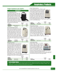
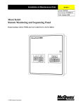
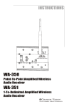
Aria
Aria
4x6 Amplified AV System
A4623
By Channel Vision
4x6 Amplified AV System
A4623R
By Channel Vision
A4623
A4623R
4-input 6-zone Amplified AV System
By
8
The A4623/A4623R is a 4 input 6 zone matrix A/V controller with an
integrated amplifier designed for whole-house audio/video distribution. The
unit provides both pre-amp outputs and speaker level outputs for each of the
6 zones making it easy to add a higher power amplifier for more demanding
applications. Any of the 4 source inputs can be selected and routed to any of
the 6 outputs (or zones) independent of the other zones.
Features:
! Built-in Amplifiers: 20Watts per channel
! Pre-amp outputs for adding more amplification
! Distributes 4 A/V sources to 6 different zones
! IR and Serial Control options
! Cost effective and easy to install
Dimensions do not include the rubber feet on the bottom of the unit or
connectors which protrude from the rear of the unit. Rubber feet will add 0.5” to
the height and connectors (without wires attached) will add 0.5” to the depth.
A4623
14.5”
Aria
A4623R
4x6 Amplified AV System
A4623
By Channel Vision
Aria
4x6 Amplified AV System
A4623R
By Channel Vision
3.50”
16.75”
19.0”
Accessories
(Sold Separately)
A0127 ... IR repeating keypad. The A0127 already
contains the IR codes necessary to operate the A4623,
but you may also use a standard IR receiver or a 3rd
party keypad. When using a simple IR receiver, you will
need to use the A0501remote control which contains
the IR codes to control the A4623. These codes can be
downloaded from www.channelvision.com, or learned
from an A0501 remote control.
Vid 1
Vol
+
Vid 2
Vid 3
Vol
-
Vid 4
Pwr
Mute
POWER
S
O
U
R
C
E
TM
1
2
3
4
MUTE
C HANNEL V ISION
MODEL
A0501
ZONE
POWER
VOL
A0501, A0502, or A0505 ... Remote control. Contains
IR codes for controlling the A4623 as well as many
other Channel Vision audio products. (A0501 shown).
IR-3001 & IR-3002 ... Single and dual head IR flashers.
Use one head per source to control from the remote
room. (IR-3002 shown).
2
IMPORTANT SAFETY INSTRUCTIONS
1. Read these instructions.
2. Keep these instructions for future reference
3. Heed all warnings.
4. Follow all instructions.
5. Do not use this device near water.
6. Clean only with a dry cloth.
7 Do not block any ventilation openings. Install in accordance with these
instructions.
8. Do not install near any heat sources such as radiators, heat registers,
stoves, or other apparatus (including amplifiers) that produce heat. When
installing multiple amplifiers in the same rack, provide space for air
circulation above and below each unit.
9. Do not defeat the safety purpose of the polarized or grounding-type
plug. A polarized plug, has two blades with one wider than the other. A
grounding type plug has two blades and a third grounding prong. the wide
blade or the third prong are provided fro your safety. If the provided plug
does not fit into your outlet, consult an electrician for replacement of the
obsolete outlet..
10. Protect the power cord from being walked on or pinched particularly at
plugs, convenience receptacles, and the point where they exit from the
apparatus.
11. Only use attachments/accessories specified by Channel Vision.
12. Use only with the cart, stand, tripod, bracket, or table specified by the
manufacturer, or sold with the apparatus. When a cart is used, use caution
when moving the cart/apparatus combination to avoid injury from tip-over.
13. Unplug this apparatus during lightning storms or when unused for long
periods of time.
14. Refer all servicing to qualified service personnel. Servicing is required
when the apparatus has been damaged in any way, such as power supply
cord or plug is damaged, liquid has been spilled or objects have fallen into
the apparatus, the apparatus has been exposed to rain or moisture, does
not operate normally, or has been dropped.
15. Where the mains plug or an appliance coupler is used as the
disconnect device, the disconnect device shall remain readily operable.
16.
CAUTION
RISK OF ELECTRIC SHOCK
DO NOT OPEN
!
Warning: To reduce the risk of electric shock, do not remove the cover (or
back), no user serviceable parts inside, refer servicing to qualified service
personnel.
Note: at frequencies between 150kHz to 1GHz, any deterioration of the
sound and picture is so minor that the system could still be used and will
function normally.
3
A4623
A0127
Front
Rear
Pin 8: +VDC
Pin 4: IR signal
N.C.
Pin 7: Ground
Vid 1
Vol
+
Vid 2
Vid 3
Pin 7: G
round
Pi n 8 : +
VDC
signal
Pin 4: IR
Pin 4: IR
signal
Pin 7: G
ro u n d
Pin 8: +
VD C
Wiring the A0127 keypad...
Keypads connect to the A4623 through the
RJ-45 jacks on the back panel of the A4623
Connections to the A0127 may be
accomplished either by using the RJ-45 jack
or the screw terminals provided on the back
side of the keypad. When using the RJ-45
jacks, simply wire both ends of the cable
according to the TIA568A standard. When
using the screw terminals on the A0127, make
sure to wire the RJ-45 plug connecting to the
A4623 as shown below.
Vol
-
Vid 4
Pwr
Mute
Connecting a standard IR repeater to the A4623... A standard
IR repeating device may be connected directly to the A4623
allowing the unit to be controlled from a learning IR remote. The
connection is similar to the wiring configuration shown above for
the A0127, except there are only three wires as shown below.
Typical IR receiver
connection
Pin 8: +VDC
Pin 7: Ground
Pin 4: IR signal
Note: not all IR receivers have the voltage,
ground, and signal connections in the same
order as this diagram. Pin 8: +VDC, Pin 7:
Ground, Pin 4: IR.
4
Using the A0501 remote control...
The A0501 is designed to allow you to control your A4623 without having to
touch the buttons on the A0127. Simply point the A0501 remote control at the
IR sensor located at the bottom of the A0127 and press the desired button.
Zone Power - Turns on/off the zone you are in
Power - Master power for A4623 (turns all zones on/off)
C HANNEL V ISION
TM
POWER
MODEL
A0501
Vid 1
1
Vol
+
Vid 2
S
O
U
R
C
E
2
Source Buttons
Vid 3
Vol
-
3
Vid 4
4
ZONE
POWER
Pwr
Mute
MUTE
VOL
Mute - Mutes the audio
for the zone you are in
C HANNEL V ISION
TM
POWER
MODEL
A0501
VOL - Controls volume
for the zone you are in
1
S
O
U
R
C
E
2
3
4
ZONE
POWER
MUTE
VOL
Downloading IR commands for the A4623...
If you don’t have access to the A0501 remote and you need to program a
learning remote, you can download the IR codes from the internet. IR codes
compatible with the Philips Pronto remote controls can be downloaded from
the following websites:
www.channelvision.com (Hex codes are also available)
www.remotecentral.com
5
A4623 Re
Each zone is controlled through the A0127 keypad
which connects to the RJ-45 jacks on the rear panel.
See page 4 for connection details
Connect serial data controller
to the Serial port
(Hex codes on pages 8-11)
6 Control 5
4 Control 3
O
U
T
P
U
T
5
6
R-AUDIO-L
S
P
E
A
K
E
R
O
U
T
P
U
T
S
VIDEO
2 Control 1
O
U
T
P
U
T
3
4
R-AUDIO-L
VIDEO
+ R - - L +
+ R - - L +
+ R - - L +
+ R - - L +
6
5
4
3
2
CAT5
16 AWG
Vid 1
Vid 3
Vol
+
Vol
-
Vid 4
Pwr
Mute
A0127
TV or Video Display
Room 6
6
R-AUDIO-L
+ R - - L +
RG6
Vid 2
O
U
T
P
U
T
+ R
ear Panel
Sat radio
Power switch
DVD player
CD player
POWER
115
IR Emitters
Link
Input Voltage
OFF
Serial
1
Hi-Z
75
1234
2
4
VIDEO
R-AUDIO-L
VIDEO
R-AUDIO-L
Warning:
R - - L +
Channel Vision
A4623 To prevent fire or shock hazard do not expose this unit to
rain or moisture.
Tested To Comply
With FCC Standards
1
1 I
N
P
U
2 T
3
FOR HOME OR OFFICE USE
CAUTION
C
U
VIDEO
T1.6AL/250V 230VAC
®
US
ON
~
230/115V
50/60 Hz MAX 115W
FUSE
RISK OF ELECTRIC SHOCK
DO NOT OPEN
T3.15AL/250V 115VAC
Main Power Fuse
IR Link allows two A4623 units to be joined
so that IR signals picked up by the keypads
of the first unit can be shared to the second
unit. The IR-4180 cable can be used to link
two units together.
IR emitter outputs allow IR-3002 flashers to
be connected for remote control of source
components.
Switch for 110-120V or 220-240V operation
Main Power Input connection
When splitting the video signal from a source component, use
the dip switch to enable the Hi-Z mode on that input.
Removable screw terminals for speaker wires provide an
excellent connection and allow speaker wires to be connected
and disconnected very quickly.
7
RS-232 Control Code:
For installations requiring more sophistication the A4623 supports RS-232
making it well suited for use with automation systems.
Baud Rate: 19200, 8N1 (8Bit Data, No Parity, 1 Stop Bit)
Each transmission = 8 ASCII bytes
Check Sum = The sum of the first 7 bytes inverted and truncated
Note: the check sum for each command is included in the following charts.
There are two possible responses generated when a command is received:
ack - This acknowledges that the command was received and it had a valid
check sum.
ZZZ - This means that the command was not understood or could not be
decoded correctly. It could also mean that the check sum was not valid.
Serial Cable Pin Out
A4623 RS-232 Pins
DB-9P, Female
PC RS-232 Pins
DB-9P, Male
Zone 1 Commands
8
Function
ASCII Command
Hex Command
Zone 1 Power Toggle
A46Z1PL-
41 34 36 5A 31 50 4C 2D
All Power Toggle
A46Z1PA8
41 34 36 5A 31 50 41 38
Zone 1, Select Source 1
A46Z1S1E
41 34 36 5A 31 53 31 45
Zone 1, Select Source 2
A46Z1S2D
41 34 36 5A 31 53 32 44
Zone 1, Select Source 3
A46Z1S3C
41 34 36 5A 31 53 33 43
Zone 1, Select Source 4
A46Z1S4B
41 34 36 5A 31 53 34 42.
Zone 1, Volume Up
A46Z1V+H
41 34 36 5A 31 56 2B 48
Zone 1, Volume Down
A46Z1V-F
41 34 36 5A 31 56 2D 46
Zone 1, Volume Reset
A46Z1VC0
41 34 36 5A 31 56 43 30
Zone 1, Mute
A46Z1MT+
41 34 36 5A 31 4D 54 28
Zone 1, Request Status
A46Z1SF0
41 34 36 5A 31 53 46 30
Zone 1, Status Clear
A46Z1SC3
41 34 36 5A 31 53 43 33
Zone 2 Commands
Function
ASCII Command
Hex Command
Zone 2 Power Toggle
A46Z2PL’
41 34 36 5A 32 50 4C 2C
All Power Toggle
A46Z2PA7
41 34 36 5A 32 50 41 37
Zone 2, Select Source 1
A46Z2S1D
41 34 36 5A 32 53 31 44
Zone 2, Select Source 2
A46Z2S2C
41 34 36 5A 32 53 32 43
Zone 2, Select Source 3
A46Z2S3B
41 34 36 5A 32 53 33 42
Zone 2, Select Source 4
A46Z2S4A
41 34 36 5A 32 53 34 41
Zone 2, Volume Up
A46Z2V+G
41 34 36 5A 32 56 2B 47
Zone 2, Volume Down
A46Z2V-E
41 34 36 5A 32 56 2D 45
Zone 2, Volume Reset
A46Z2VC/
41 34 36 5A 32 56 43 2F
Zone 2, Mute
A46Z2MT’
41 34 36 5A 32 4D 54 27
Zone 2, Request Status
A46Z2SF/
41 34 36 5A 32 53 46 2F
Zone 2, Status Clear
A46Z2SC2
41 34 36 5A 32 53 43 32
Function
ASCII Command
Hex Command
Zone 3 Power Toggle
A46Z3PL+
41 34 36 5A 33 50 4C 2B
All Power Toggle
A46Z3PA6
41 34 36 5A 33 50 41 36
Zone 3, Select Source 1
A46Z3S1C
41 34 36 5A 33 53 31 43
Zone 3, Select Source 2
A46Z3S2B
41 34 36 5A 33 53 32 42
Zone 3, Select Source 3
A46Z3S3A
41 34 36 5A 33 53 33 41
Zone 3, Select Source 4
A46Z3S4@
41 34 36 5A 33 53 34 40
Zone 3, Volume Up
A46Z3V+F
41 34 36 5A 33 56 2B 46
Zone 3, Volume Down
A46Z3V-D
41 34 36 5A 33 56 2D 44
Zone 3, Volume Reset
A46Z3VC.
41 34 36 5A 33 56 43 2E
Zone 3, Mute
A46Z3MT&
41 34 36 5A 33 4D 54 26
Zone 3, Request Status
A46Z3SF.
41 34 36 5A 33 53 46 2E
Zone 3, Status Clear
A46Z3SC1
41 34 36 5A 33 53 43 31
Zone 3 Commands
9
Zone 4 Commands
Function
ASCII Command
Hex Command
Zone 4 Power Toggle
A46Z4PL*
41 34 36 5A 34 50 4C 2A
All Power Toggle
A46Z4PA5
41 34 36 5A 34 50 41 35
Zone 4, Select Source 1
A46Z4S1B
41 34 36 5A 34 53 31 42
Zone 4, Select Source 2
A46Z4S2A
41 34 36 5A 34 53 32 41
Zone 4, Select Source 3
A46Z4S3@
41 34 36 5A 34 53 33 40
Zone 4, Select Source 4
A46Z4S4?
41 34 36 5A 34 53 34 3F
Zone 4, Volume Up
A46Z4V+E
41 34 36 5A 34 56 2B 45
Zone 4, Volume Down
A46Z4V-C
41 34 36 5A 34 56 2D 43
Zone 4, Volume Reset
A46Z4VC-
41 34 36 5A 34 56 43 2D
Zone 4, Mute
A46Z4MT%
41 34 36 5A 34 4D 54 25
Zone 4, Request Status
A46Z4SF-
41 34 36 5A 34 53 46 2D
Zone 4, Status Clear
A46Z4SC0
41 34 36 5A 34 53 43 30
Function
ASCII Command
Hex Command
Zone 5 Power Toggle
A46Z5PL)
41 34 36 5A 35 50 4C 29
All Power Toggle
A46Z5PA4
41 34 36 5A 35 50 41 34
Zone 5, Select Source 1
A46Z5S1A
41 34 36 5A 35 53 31 41
Zone 5, Select Source 2
A46Z5S2@
41 34 36 5A 35 53 32 40
Zone 5, Select Source 3
A46Z5S3?
41 34 36 5A 35 53 33 3F
Zone 5, Select Source 4
A46Z5S4>
41 34 36 5A 35 53 34 3E
Zone 5, Volume Up
A46Z5V+D
41 34 36 5A 35 56 2B 44
Zone 5, Volume Down
A46Z5V-B
41 34 36 5A 35 56 2D 42
Zone 5, Volume Reset
A46Z5VC’
41 34 36 5A 35 56 43 2C
Zone 5, Mute
A46Z5MT$
41 34 36 5A 35 4D 54 24
Zone 5, Request Status
A46Z5SF’
41 34 36 5A 35 53 46 2C
Zone 5, Status Clear
A46Z5SC/
41 34 36 5A 35 53 43 2F
Zone 5 Commands
10
Zone 6 Commands
Function
ASCII Command
Hex Command
Zone 6 Power Toggle
A46Z6PL(
41 34 36 5A 36 50 4C 28
All Power Toggle
A46Z6PA3
41 34 36 5A 36 50 41 33
Zone 6, Select Source 1
A46Z6S1@
41 34 36 5A 36 53 31 40
Zone 6, Select Source 2
A46Z6S2?
41 34 36 5A 36 53 32 3F
Zone 6, Select Source 3
A46Z6S3>
41 34 36 5A 36 53 33 3E
Zone 6, Select Source 4
A46Z6S4=
41 34 36 5A 36 53 34 3D
Zone 6, Volume Up
A46Z6V+C
41 34 36 5A 36 56 2B 43
Zone 6, Volume Down
A46Z6V-A
41 34 36 5A 36 56 2D 41
Zone 6, Volume Reset
A46Z6VC+
41 34 36 5A 36 56 43 2B
Zone 6, Mute
A46Z6MT#
41 34 36 5A 36 4D 54 23
Zone 6, Request Status
A46Z6SF+
41 34 36 5A 36 53 46 2B
Zone 6, Status Clear
A46Z6SC.
41 34 36 5A 36 53 43 2E
Function
ASCII Command
Hex Command
Global, Zone Power Toggle
A46ZAPL[group sep]
41 34 36 5A 41 50 4C 1D
Global, Select Source 1
A46ZAS15
41 34 36 5A 41 53 31 35
Global, Select Source 2
A46ZAS24
41 34 36 5A 41 53 32 34
Global, Select Source 3
A46ZAS33
41 34 36 5A 41 53 33 33
Global, Select Source 4
A46ZAS42
41 34 36 5A 41 53 34 32
Global, Volume Up
A46ZAV+8
41 34 36 5A 41 56 2B 38
Global, Volume Down
A46ZAV-6
41 34 36 5A 41 56 2D 36
Global, Volume Reset
A46ZAVC[sp]
41 34 36 5A 41 56 43 20
Global, Mute
A46ZAMT[cancel]
41 34 36 5A 41 4D 54 18
Global, Request Status
A46ZASF[sp]
41 34 36 5A 41 53 46 20
Global, Status Clear
A46ZASC#
41 34 36 5A 41 53 43 23
Global Commands
Note: this chart contains some ASCII commands that include non-standard
ASCII characters (characters which are not included on a standard keyboard).
When programming a controller with these functions, it may be necessary to
use the Hexadecimal equivalent shown in the far right hand column.
11
Channel Vision Technology will repair or replace any defect in material or
workmanship which occurs during normal use of this product with new or rebuilt
parts, free of charge in the USA, for two years from the date of original purchase.
This is a no hassle warranty with no mail in warranty card needed. This warranty
does not cover damages in shipment, failures caused by other products not
supplied by Channel Vision Technology, or failures due to accident, misuse, abuse,
or alteration of the equipment. This warranty is extended only to the original
purchaser, and a purchase receipt, invoice, or other proof of original purchase date
will be required before warranty repairs are provided.
Mail in service can be obtained during the warranty period by calling (800) 8400288 toll free. A Return Authorization number must be obtained in advance and
can be marked on the outside of the shipping carton.
This warranty gives you specific legal rights and you may have other rights (which
vary from state to state). If a problem with this product develops during or after the
warranty period, please contact Channel Vision Technology, your dealer or any
factory-authorized service center.
Specifications: (typical @25º C)
Audio
Bandwidth:
Power Output:
S/N ratio:
THD:
20-20kHz +/- 3dB
20W per channel
>80dB
< 0.5%
Video
Bandwidth:
Crosstalk:
DC-20MHz
-60 dB
Specifications subject to change without notice.
www.channelvision.com
234 Fischer Avenue, Costa Mesa, California 92626 USA
(714)424-6500 (800)840-0288 (714)424-6510 fax
email: [email protected]
500-192 rev D