1
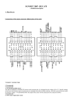
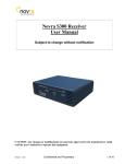
II
IIII
,Advanced software concepts for
employing microcomputers in the
laboratory
Scott B. Tilden and M.Bonner Denton,
Department of Chemistry, University of Arizona, Tucson, Arizona 85721, USA.
Introduction
While a proliferation of commercial chemical instrumentation is appearing today employing microprocessors for a
variety of control and data reduction applications, the great
potential of microprocessors has not been exploited
extensively for individual custom applications. The primary
reason for this phenomenon is altogether too clear microprocessor software is either difficult to develop or inefficient
in memory requirements and speed. This problem is even
more important in situations requiring constant software
Interpretative
Machine Code
modification. Initially, most instrument manufacturers
utilized cross assemblers supported on large "number
cruncher" computers to generate the required machine code
binary program. More recently, the trend has been toward
the use of a "developmental system" (at a cost comparable
to a moderate minicomputer- the authors use the term
"mini" in contrast to "micro" reluctantly because of the ever
increasing overlap in computing capability) to write and
debug assembly level porgrams which are subsequently converted to binary and incorporated into an instrument in the
form of "read only memory" (ROM). While this approach
Source Code File
to Execute
Command A
Hachine Code
to Execute
Comma nd B
Various
’commands
making up
,lachi
ne Code
to Execute
Command C
i
users source
program
Machine Code
to Execute
Command D
etc.
Figure 1. The interpretative cycle of common types of languages
such as BASIC. After examining each command in the source file,
the interpreter searches for and branches to the corresponding
block of machine code; thus, program execution always remains
within the interpreter.
128
The Journal of Automatic Chemistry
Tilden & Denton
IIII
Advanced software concepts
III
Users Source
File
The Compiler
Command A
/z/
Comma nd B
Command C
II
li
i
etc.
.
.lachi ne Code
Command D
etc.
to Execute
Command A
etc.
Machine Code
to Execute
Machine Code
to Execute
Command C
Machine Code
etc.
Note that the compiler transforms each source
"command" into executable machine code. This code will, subsequently, be loaded and executed independently of the compiler.
Figure 2.
has proven cost effective for high volume mass produced
applications, it possesses serious limitations for system updates and custom applications. Additionally, the ability to
program efficiently at the assembly level is a talent requiring
a significant expenditure of time to develop.
During the past several years, a virtual deluge of sophisticated, flexible, high performance computer hardware has
been introduced primarily aimed at a rapidly growing
"hobbyist" market. Manufacturers quickly realilsed that to
sell the public hardware, some form of reasonably high level
software must be made available. A variety of BASIC interpreters, ranging from rather "dumb" to "quite intelligent"
have since evolved. The more intelligent BASIC interpreters
have several highly attractive attributes for "hobbyist"
applications. The language is both easy to master and conversational. Error and caution messages are provided as aids
during programming.
Why not apply the "hobbyist" technology toward the
implementation of custom laboratory systems? Many investigators have and, no doubt, many more will take this
approach. However, BASIC interpreters possess serious
limitations in terms of system speed, flexibility and input/
output (I/O) capabilities. In BASIC, each command must
first be interpreted and then executed (see Figure 1). In
many cases, the interpretation process takes much more time
than the actual execution. This problem is compounded by
the fact that commands interpreted in the past must be
re-interpreted each time they are used causing iterative
programs to be very slow. While speed is often not a serious
limitation in playing computer games, laboratory application requiring high speed data acquisition and/or data
manipulation are common. Additionally, the more intelligent
BASICs make very inefficient use of memory often requiring
minimum of 12 or 16 K bytes (twelve or sixteen thousand
eight bit words)’
Volume
No. 3 April 1979
cS
H
A
D
H
Figure 3. The ’threaded’ code approach used in CONVERS. In
’threaded’ code programming modules for sub-routines are used
repetitively in a variety of combinations to allow implementation
of an infinite number of functions. Note that the flow of logic
threads its way in a very non.linear fashion through these modules.
129
Tilden
& Denton
Advanced software concepts
|I
Upper Memory Bound
Stack
User’s Application
Dictionaries
4.5k Octal
CONVERS-Di sk
Operating System
3.7k Octal
Standard High
Level Dictionary
1.2k Octal
Initial Machine
Code Dictionary
I@@ Octal
Figure 4. Memory map of the CON VERS dictionary. The stack
which is composed of data parameters etc. acts as a constantly
expanding or contracting memory buffer which allows one subroutine to communicate with another without either needing to
know the other’s location.
In contrast to interpreters, high level compilers, such as
FORTRAN, offer a much faster "run time" execution speed.
This is accomplished through generation of the required
machine code during a series of programming operations.
Compilers using FORTRAN, which are designed to run on
many minicomputers and some micros, often first transform
user symbolic source code into assembly code. An assembler
program, subsequently, transforms this into the required
machine code. This ready-to-run machine code is often
loaded along with a run time package which executes in the
manner shown in Figure 2. While this approach greatly
improves execution speed, the need for loading several
different soft-ware routines increases the "hassle" associated
with editing and debugging. Thus, this makes some form of
mass memory, such as a disk or magnetic tape, almost
mandatory. Additionally, I/O algorithms generally must
be implemented in assembly level code!
One obvious question immediately arises- why not
incorporate the most desirable characteristics of both interpreters and compilers into a single language? Additionally,
due to the unique requirements found in many applications, why not allow the programmer additional flexibility
by providing him with the ability to actually develop his own
individual modifications and additions to the language itself?
Other desirable features would include high memory
efficiency, high level I]O programming, ease of understanding
the language’s "inter-working" and the ability to be transferred from one CPU to another with minimum effort.
Type "ACQUIRE"
ACQUIRE
# of characters
A
G
FORMAT T
PLOT
START
SCAN
GALC%T
DISPLAY
RETURN
EXECUTIVE
Figure 5. If a previously defined program name (A CO U R tQ is
entered when in EXECUTE mode, a dictionary search takes
place locating the ACQUIRE entry. Once found, this entry
contains all the required machine code and/or calls to addresses of
other previously compiled machine code modules to completely
execute the desired function.
130
The Journal of Automatic Chemistry
Tilden & Denton
2000
VARIABLE
START
5000
VARIABLE
STOP
20
VARIABLE
INCREMENT
0
VARIABLE
LOCATION
A/D7
INDEVICE
7
INITIALIZE
STEP
START
LOCATION
DELAY
@
BEGIN-HERE
MOVE
LOCATION
SCAN
INITIALIZE
END
ELSE
BEGIN
3000
START
6500
START
10
Advanced software concepts
@
@
LOCATION
INCREMENT
5
INDEVICE
5
OUTDEVICE
BEGIN-HERE
+
@
10
LOCATION
AND
STEP
MOVE
IF
A/D7
BEGIN
ELSE
THEN
DELAY
LOCATION
@
STOP
@
>
IF
THEN
INCREMENT
SCAN
Figure 6. Ten lines of typical CONVERS code to scan wavelengths
between two easily changed limits and acquire data. By reference
to notes in the text it can be easily understood.
NOTE: a number or name pushes the number of address occupied
by the name on the stack. The symbol @, pips the top number
from the stack uses it as the address from which to obtain a
number and pushes that number on the stack.
Development of CONVERS
During the past two years, a different approach to software has been taking place at the University of Arizona
referred to as an "Interpretive Compiler" called CONVERS.
This package, which is conceptually similar to the FORTH
language currently being used in several minicomputerastronomical applications
], is able to provide many of the
desirable features found in both interpreters and compilers
by separating the compile and execute states (as a compiler
does) while maintaining a resident user interactive and
conversational executive which oversees system operation.
The ability to realise such advanced software capabilities
in a very modest amount of memory (less than 4 K bytes
on an 8080 based micro) is the direct result of exploiting
threaded code programming techniques (see Figure 3). The
approach involves highly efficient use of simple macroinstructions to build more complex subroutines which are
recombined with additional macroinstructions to form super
subroutines. This process of combining previously defined
modules to form ever increasingly sophisticated routines
for performing the task at hand is the essence of threaded
code programming. When initially loaded and running,
CONVERS acts much like an interpreter, i.e. it is conversational, ready to either execute a previously programmed
algorithm or accept a new one. However, in contrast to
BASIC, when a new program is being entered under
CONVERS, it is immediately transformed into binary
machine code or to the binary starting addresses of other
previously entered and compiled machine code programs.
During this process, the operator is kept informed of the
status of the program by a series of error and diagnostic
Volume
No. 3 April 1979
messages. When the new program has been completed, it is
entered in a program library or dictionary, which is constantly building up from low memory (see Figure 4). If the
operator now wants to execute this program, he can request
it from his terminal. A dictionary search will begin at the last
entry and progress until the requested program is located.
Once located, the requested program will run in its entirety
without need for any additional dictionary searches. For
example, let us assume an algorithm, called ACQUIRE,
has been programmed to take data from some hypothetical
experimental system. When ACQUIRE is requested from the
terminal, a dictionary search is initiated. The program names
ACQUIRE (see Figure 5), once located, contains the starting
addresses of a series of previously defined modules which
implement the various steps necessary to perform the desired
experiment. For example, the module SCAN which might be
intended to scan a monochromator’s wavelength in some
desired manner has been previously defined and tested. This
ability to easily test each module separately and then
efficiently combine a series of modules to perform a more
complex function, test this function, and then employ .it in
a vastly more complex function, etc., i.e. testing each step
as the threaded code is made increasingly complex, is a major
factor contributing to the speed with which software can be
developed using CONVERS. Use of a software stack also
contributes toward improved memory efficiency and simplified programming.
The stack is an area of memory set aside to handle
parameters, data numbers, etc. One of the primary
advantages of the stack is that entries can leave temporary
parameters on the stack without having to assign specific
131
Tilden & Denton
Advanced software concepts
DUAL REGULATED
POWER SUPPLY
I0 KV
I00
PIEZOELECTRIC
TRANSLATOR
GRATING
,..
MIRROR
C02He, N2
OP TOACOUS TIC
CELL
POWER
DE TECTOR
CHOPPER
TRANSLATOR
STEPPER
MOTOR
DRIVER
LOCK-IN
AMP
ADC
CONTROLLER
LOCK- IN
AMP
MICROFLOPPY
DISK
24K RAM
1
Figure 7. The optoacoustic experiment in which a microcomputer
is used to control laser wavelength and to monitor laser power and
optoacoustic signal.
memory locations to store them. This not only can save
considerable memory, but also allows programs to be easily
relocatable since one algorithm need only know that a
previous routine left so many words of data, etc. on the
stack. It need not know where the previous routine is nor
even where the stack is located. A series of stack handling
routines, which should appear quite familiar to many small
calculator users, provide an array of capabilities, including
the ability to PUSH a number on the stack, POP ,it off,
duplicate it, SWAP the top two numbers, locate a number
some distance into the stack, and copy it on top of the stack,
etc. Additionally, a variety of logic functions familiar to the
minicomputer user are provided including OR, AND, shift
left, shift right, greater than, less than, etc.
Input/output (I/O) is normally accomplished using the
stack in conjunction with the INDEVICE or OUTDEVICE
commands. For example, to take data from a device located
at I/O, port 7, the number seven is "pushed" onto the stack
(7), goes to this I/O port, takes in a number and "pushes"
the number on the stack. OUTDEVICE functions in a similar
manner, requiring the number to be sent to the desired
device to be "pushed" onto the stack followed by the
device’s I/O port address. Hence, to send the number 131 to
device 11, the number 131 is pushed on the stack followed
by 11 and then OUTDEVICE. This "pops" the top number
(11) from the stack, uses it as the output port and then sends
the number 131 to that location.
Applications of CONVERS
To appreciate the ease with which real programs can be
written, a few examples will be considered. A trivial program,
called SOUND, which rings the terminal bell three times,
might be written:
132
BELL
SOUND
BELL
BELL
The colon denotes changing from EXECUTE to COMPILE
mode. After typing the name of the new routine, in this case
to be called SOUND, typing the name of the earlier defined
routine (BELL
a previously defined simple program to
rng the terminal bell) initiates a dictionary search to locate
this routine’s starting address which subsequentially is entered
three times. The resulting SOUND routine contains machine
code calls to the BE LL routine which, itself, is composed of
machine code. Of course, SOUND could also have been
defined using a DO-LOOP, i.e.
SOUND
DO
3
BELL
LOOP
where the numbers three and one set the upper and lower
indices. If it were desirable to change the actual number of
bell rings from some other program, this value could be
defined as a VARIABLE let’s call it NOISE.
3
VARIABLE NOISE
In this case, the number three is first pushed on the stack,
VARIABLE transfers the top number on the stack (the
three) to a dictionary location named NOISE. If SOUND
were now defined as:
SOUND
NOISE
@
DO
BELL
LOOP
the bell would again ring three times. In this case, when the
word NOISE iS encountered, its address is pushed on the
stack, the @ is a simple program which goes to the address
indicated on the top of the stack (that of NOISE)and
replaces it with the actual value located at that address (the
number three). At any future time, the value of
VARIABLE can be changed by "pushing" the new value
onto the stack, followed by the address of the variable to be
changed, generated by its name and an exclamation mark. To
change N O IS E to 5,
The Journal of Automatic Chemistry
Tilden & Denton
5 NOISE
a number five is pushed onto the stack, NOISE pushes its
address on the stack, and goes to the address indicated by
the "top" number on the stack and deposits the next
number. Now sound would ring the terminal bell five times.
A much less trivial program which could be written to scan
and take data from a monochromator equipped with a
DENCO SM2A stepper motor controller [2] (the SM2A
takes a parallel number as an address, sends one of two
stepper motors to this location and outputs an arrival flag
when the address is reached) is given in Figure 6. Assume
that the experimental system is configured so the SM2A is at
I/O, port 5 and an analog to digital converter to acquire data
is at I/O, port 7. Let us assume that, initially, a scan is
designed from a starting stepper motor location of 2000 to a
final location of 5000, taking data every 20 steps.
The program illustrated in figure 6 acts in the following
manner. Line defines a variable called START to be 2000,
which is the starting location of fhe scan. The end of the scan
is defined as 5000 in the next line. Line 3 defines the
increment between data points. A variable called LOCATION
where the. next address is stored is defined in line 4.. Colon, in
line 5, puts the system in the compile mode, A/D7 will be
the name of the module which when called will cause a 7 to
be pushed onto the stack. INDEVICE will ’pop’ it back off
and use it as a device address to go and take a data point and
push the data onto the stack. Line 6 defines a module
INITIALIZE, START puts its address on the stack, @
replaces the address with the value at that address, LOCATION puts its address on the stack, ’!’ goes to the address
specified by the number on the stack and deposits the second
number and the net result value at START is put into
LOCATION. Line 7 defines STEP to take values from
Advanced software concepts
LOCATION and INCREMENT adds them together and puts
the result into LOCATION, i.e. LOCATION puts its address
on the stack, @ replaces the top value on the stack with the
number stored at the address, INCREMENT @ gets the value
at INCREMENT and puts it in to the stack, and adds the top
two stack numbers and pushes the result on the stack.
LOCATION puts its address on the stack and goes to the
address specified by the top number on the stack and
deposits the second number. Themodule defined in line 8
takes a number from the stepper motor controller (assume
device numbered 5) pushes on the stack, and pushes the
value 10 on the stack and does a logical AND to see if the
controllers flag is set, if this is true the A/D7 module will be
called to input data, if the flag is not set, the program is
returned to BEGIN-HERE. Therefore the DELAY module
is a loop waiting for the stepper motor to arrive at its new
location followed by a call to A/D7 data acquisition module.
MOVE defined in line 9 gets the value stored at LOCATION
pushes the device code onto the stack performs an outdevice
(which uses the top stack number as a 1/0 port address to
send the next value to call the STEP module (ie the value
at LOCATION), this increments LOCATION by the INCREM E N T value and finally calls D E L A Y and waits for a flag
from the stepper motor controller to signal its arrival at the
desired address and then takes a data point. The final line
shown in the example Called SCAN itself calls the INITIALIZE module (which sets LOCATION to the START location
for the Scan) it also calls MOVE (which sends this value to
the motor LOCATION controller, increments the value
stored in LOCATION by INCREMENT and calls DELAY
which waits for the motor to arrive and then takes a data
point). Next the incremented value from LOCATION is
placed on the stack (LOCATION) followed by the STOP
I0 KW
AMPLIFIER
MATCHING
,NETWORKIS
PREAMP
MOTOR
CON TROL ER
MICRODISK
90K byte
INTEL 8080 based
MICROCOMPUTER
16K
RAM
Figure 8. A schematic of the inductively coupled plasma emission
spectrometer in which the microcomputer is used to control radio
frequency power and ’flame’ positioning as well as to monitor
light intensity.
Volume
No. 3 April 1979
133
Tilden & Denton
Advanced software concepts
>
value (STOP @ ), the two are compared to
to see if the
incremented value at LOCATION is larger then the STOP
value, if it is the program ends, if not, it repeats the
process starting at BEGIN--HERE.
It should be noted that whilst many variables have been
pushed on the stack, only the data will remain, since each
time a value is used it is ’popped’ (removed) from the stack.
If a different spectra region is to be scanned i.e. from 3000
to 6500 with 10 increments the variables need only be
changed thus
3000 START!
6500 STOP
10 INCREMENT
and type SCAN, system will now scan from 3000 to 6500
taking data every 10 steps.
While the code might look a little strange at first, it
quickly becomes very easy to work with. The SCAN program
of Figure 6 could be combined with other modules as shown
in Figure 5 to perform some more complex experimental
function. Each module of the program can be easily tried out
to ensure that it is operational before proceeding with the
next.
Presently, CONVERS is being used in the authors’
laboratories for a variety of spectrochemical investigations,
including laser excited optoacoustic spectroscopy (Figure 7)
and inductively coupled plasma optical emission spectroscopy (Figure 8). Rather complex interactive control and
data acquisition programs have been easily implemented.
Memory requirements and operating speed have been found
to be far superior to conventional approaches. Additionally,
new system users have encountered a difficulty in utilising
previously developed custom software for a particular
experiment even when documentation was vague.
Discussion
The authors hope that this short introduction to only a
few of the concepts employed in CONVERS will generate
interest in its capabilities. A much more complete discussion
is available in the form of a user’s manual [3] available from
the authors.
ACKNOWLEDGEMENTS
The development of the CONVERS system was partially supported
by the Office of Naval Research and a Alfred P. Cloan Foundation
Research Fellowship to M. Bonnet Denton.
REFERENCES
C. Moore, Astronomical Astrophysics Supplemental, 15,(1974)
497.
[2] M.B. Denton, J.D. Mack, M.W. Routh and D.B. SwartzClmerican
[3]
Laboratory,8,69 (1976).
CONVERS An Interpretive Compiler, developed by Scott B.
Tilden and M. Bonner Denton, Department of Chemistry,
University of Arizona, Tucson, Arizona 85721, USA.
The use of a microcomputer for
flexible automation of a liquid
chromatograph
A.D. Mills, i. Mackenzie and R.J. Dolphin*
Philips Research Laboratories, Redhill, Surrey, RH1 5HA, U.K.
Introduction
Microprocessors are being used to add inexpensive automatic
control and data handling facilities to a variety of chemical
instruments. With a microcomputer it is now possible to
realise the flexibility formerly available only with a relatively
large and expensive minicomputer in an instrument little
different in size and cost from one controlled by inflexible
hardware. In many ways chromatography is an ideal process
for such automation. Most instruments are given a high
workload and, although many applications may be routine
and repetitive, the versatility of the technique requires an
instrument which can easily be used in a variety of modes.
In addition to improving the convenience to the user,
automation of a liquid chromatrograph should enhance the
performance of the instrument. Some aspects of high
performance liquid chromatography (HPLC) which can
benefit in this way are as follows:
(1) Accurate control of solvent flow rate will compensate
for changes in pressure drop and lead to more reliable
retention times.
(2) The composition of the mobile phase can be accurately
controlled in either isocratic or gradient elution chromatography using, for example, a proportioning valve on
the low pressure side of the pump.
(3) Automatic sampling can be operated in a variety of
modes to process a number of samples without supervision. It is also more precise than manual injection.
(4) A built-in data handling facility can present the analyst
*Present address: lye Unicam Ltd., York Street, Cambridge, CB1
2PX, U.K.
The computer is a general purpose instrument constructed
using a set of ready made circuit cards (Philips, Science and
134
with an easily read post-run report of the analytical
results with accurate peak area measurements even for
peaks which are poorly resolved.
Although liquid chromatographs incorporating microprocessors for control and data handling purposes are
commercially available, these instruments are, so far,
This paper describes, in detail, the
relatively inflexible.
automation of a liquid chromatograph using an inexpensive
general purpose microcomputer, which has previously been
applied in atomic absorption spectrophotometry [1] and for
column switching in HPLC 2 ].
Figure
illustrates the interconnection of the chromatograph and the microcomputer which controls the mobile
phase flow rate, operates an automatic sampler and analyses
data from the detector. The control and data handling
functions are integrated in a program which enables the
user to communicate with the instrument, in plain English,
via a visual display unit (VDU)or teletypewriter keyboard.
A variety of operational modes is offered, giving the analyst
an opportunity to establish the best conditions for a particular separation before leaving the instrument to perform its
given tasks without further interaction.
The microcomputer
Hardware
The Journal of Automatic Chemistry