1
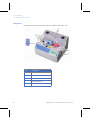
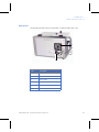
GE Healthcare
Life Sciences
STERILE TUBE FUSER DRY
Operator Manual
Press
Plunger
to
Lock Lid
Contents
1
Introduction ................................................................................. 5
1.1
1.2
1.3
1.4
1.5
1.6
2
Principle of operation...............................................................17
2.1
3
Controls ...............................................................................................................22
Operating procedure ....................................................................................24
3.2.1
3.2.2
Main operating steps.........................................................................................24
Safety precautions during operation .........................................................25
3.3
3.4
3.5
3.6
3.7
3.8
3.9
3.10
3.11
3.12
Installing and removing blades ...............................................................27
Load the tubing ...............................................................................................29
Remove the tubing ........................................................................................30
Change the tubing holders ........................................................................31
Change the tubing type ..............................................................................33
Inspecting weld quality ...............................................................................34
How to handle liquid filled tubing ...........................................................35
Using different types of tubing ................................................................35
Welding different diameters .....................................................................36
Using the printer .............................................................................................37
Troubleshooting ........................................................................39
4.1
4.2
4.3
5
Operating schematic ....................................................................................19
Operation ...................................................................................21
3.1
3.2
4
Important user information ..........................................................................5
Regulatory information ..................................................................................7
Safety precautions ...........................................................................................9
STERILE TUBE FUSER - DRY ........................................................................11
Features ..............................................................................................................14
Disclaimer ..........................................................................................................15
Error checking ..................................................................................................39
Possible issues .................................................................................................40
General troubleshooting and error messages .................................40
Specifications.............................................................................41
5.1
5.2
Specifications ...................................................................................................41
Tubing ..................................................................................................................42
Appendix A Compatible tubing ....................................................43
Appendix B Blade contact materials...........................................45
Appendix C Ordering Information ...............................................47
STERILE TUBE FUSER - DRY Operator Manual 87-4500-21 AK
3
4
STERILE TUBE FUSER - DRY Operator Manual 87-4500-21 AK
1 Introduction
1.1 Important user information
Read this before using STERILE
TUBE FUSER - DRY
All users must read the entire STERILE TUBE FUSER - DRY and HOT LIPS TUBE
SEALER™ Operating Instructions before installing, using or maintaining the
instrument. Always keep the Operating Instructions at hand when using STERILE
TUBE FUSER - DRY.
Do not operate STERILE TUBE FUSER - DRY in any other way than described in the
user documentation. If you do, you may be exposed to hazards that can lead to
personal injury and you may cause damage to the equipment.
Intended use
STERILE TUBE FUSER - DRY is an automated instrument designed to produce sterile
joints of thermoplastic tubings.
STERILE TUBE FUSER - DRY shall not be used in any clinical procedures, or for
diagnostic purposes.
Safety notices
This user documentation contains WARNINGS, CAUTIONS and NOTICES concerning
the safe use of the product. See definitions below.
STERILE TUBE FUSER - DRY Operator Manual 87-4500-21 AK
5
1 Introduction
1.1 Important user information
Warnings
WARNING
WARNING indicates a hazardous situation which, if not avoided, could result
in death or serious injury. It is important not to proceed until all stated
conditions are met and clearly understood.
Cautions
CAUTION
CAUTION indicates a hazardous situation which, if not avoided, could result
in minor or moderate injury. It is important not to proceed until all stated
conditions are met and clearly understood.
Notices
NOTICE
NOTICE indicates instructions that must be followed to avoid damage to the
product or other equipment.
Notes and tips
Note: A Note is used to indicate information that is important for trouble-free and
optimal use of the product.
Tip: A tip contains useful information that can improve or optimize your
procedures.
Typographical conventions
Software items are identified in the text by bold italic text. A colon separates menu
levels, thus File:Open refers to the Open command in the File menu. Hardware
items are identified in the text by bold text (e.g., Power switch).
6
STERILE TUBE FUSER - DRY Operator Manual 87-4500-21 AK
Introduction 1
Regulatory information 1.2
1.2
Regulatory information
This section lists the directives and standards that are fulfilled by STERILE TUBE
FUSER - DRY.
Manufacturing information
The table below summarizes the required manufacturing information. For further
information, see the EC Declaration of Conformity document.
Requirement
Content
Name and address of
manufacturer
GE Healthcare Bio-Sciences AB,
Björkgatan 30,
SE 751 84 Uppsala,
Sweden
International standards
Standard
Description
Notes
EN 61010-1,
IEC 61010-1,
UL 61010-1,
CAN/CSA-C22.2 no.
61010-1
Safety requirements for
electrical equipment for
measurement, control and
laboratory use
EN harmonized with
2006/95/EC
EN 61326-1
EMC emissions and
immunity requirements for
measurement, control and
laboratory use
Harmonized with
2004/108/EC
EN ISO 12100:2010
Safety of machinery. General
principles for design. Risk
assessment and risk
reduction.
Harmonized with
2006/42/EC
STERILE TUBE FUSER - DRY Operator Manual 87-4500-21 AK
7
1 Introduction
1.2 Regulatory information
CE conformity
Directive
Title
2006/42/EC
Machinery Directive (MD)
2006/95/EC
Low Voltage Directive (LVD)
2004/108/EC
ElectroMagnetic Compatibility
(EMC) Directive
CE marking
The CE marking and the corresponding Declaration of Conformity is valid for the
instrument when it is:
•
used as a stand-alone unit, or
•
connected to other CE-marked instruments, or
•
connected to other products recommended or described in the user
documentation, and
•
used in the same state as it was delivered from GE Healthcare, except for
alterations described in the user documentation or explicitly authorized by
GE Healthcare.
Regulatory compliance of
connected equipment
Any equipment connected to STERILE TUBE FUSER - DRY should meet the safety
requirements of EN 61010-1/IEC61010-1 or relevant harmonized standards. Within
the European Union, connected equipment must be CE-marked.
8
STERILE TUBE FUSER - DRY Operator Manual 87-4500-21 AK
Introduction 1
Safety precautions 1.3
Recycling
This symbol indicates that the waste of electrical and electronic
equipment must not be disposed as unsorted municipal waste
and must be collected separately. Please contact an authorized
representative of the manufacturer for information concerning
the decommissioning of equipment.
1.3 Safety precautions
All users must read this section and the Safety instructions chapter in STERILE
TUBE FUSER - DRY and HOT LIPS TUBE SEALER Operating Instructions before using
STERILE TUBE FUSER - DRY, and observe the safety information at all times during
use.
WARNING
The end user must ensure that all installation, maintenance,
operation and inspection is carried out by qualified personnel who
are adequately trained, understand and adhere to local regulations
and the operating instructions, and have a thorough knowledge of
the entire system and process.
WARNING
Do not operate STERILE TUBE FUSER - DRY in any other way than
described in the user documentation.
WARNING
Electrical shock hazard. All repairs should be done by service personnel
authorized by GE Healthcare. Do not open any covers or replace parts
unless specifically stated in the user documentation.
WARNING
Hot Surfaces of STERILE TUBE FUSER - DRY. The cutting blade reaches
400°C during the heating cycle. Do not try to open the protective cover
during the welding.
STERILE TUBE FUSER - DRY Operator Manual 87-4500-21 AK
9
1 Introduction
1.3 Safety precautions
WARNING
Pinch Hazard of STERILE TUBE FUSER - DRY. There are movable parts
under the protective cover. Do not try to open the protective cover during
the welding.
WARNING
Access to power switch and power cord. The power switch must always
be easy to access. The power cord must always be easy to disconnect.
WARNING
The cutting blade of STERILE TUBE FUSER - DRY is a thin piece of alloy
material. It does not have a sharpened edge but can cause cuts if
handled improperly. Be sure to read and understand the procedure of
how to install and remove the blade.
WARNING
Do not touch the blade of STERILE TUBE FUSER - DRY until it cools down.
Always allow the blade to cool down for 30 seconds before accessing the
blade.
WARNING
Depending of which tubes that are used in STERILE TUBE FUSER - DRY
hazardous gases may emit. Make sure to use the instrument in a room
with proper ventilation.
CAUTION
Only use tubing that is compatible with the instruments. Refer to
Appendix A for a list of tubing types that have been tested.
CAUTION
Do not attempt to connect liquid-filled tubing using STERILE TUBE FUSER
- DRY, or allow liquid to spill into the instrument.
10
STERILE TUBE FUSER - DRY Operator Manual 87-4500-21 AK
Introduction 1
STERILE TUBE FUSER - DRY 1.4
CAUTION
Depending on which tubes that are used in STERILE TUBE FUSER - DRY
hazardous gases may emit. Make sure to use the instrument in a room
with proper ventilation.
NOTICE
Leave space around the unit for proper ventilation.
NOTICE
Only use PTFE coated cutting blades (BLADES-IR/50) specified for use
with STERILE TUBE FUSER - DRY. For optimal use, do not reuse blades.
NOTICE
This is a class A product, input power > 1 kW, intended for professional
use. In a domestic environment it may cause radio interference, in which
case the user might be required to take appropriate measures.
1.4 STERILE TUBE FUSER - DRY
Introduction
STERILE TUBE FUSER - DRY is an automated instrument designed to produce sterile
joints of thermoplastic tubings without the need for a laminar flow cabinet or
similar environmental control unit. The machine is useful for connecting tubing
between process containers and equipment. The unit is designed to connect large
diameter tubing enabling high flow rates and large transfer volumes. Major uses
are in bioprocessing and in aseptic applications.
Note: The STERILE TUBE FUSER - DRY is not to be used for medical applications.
STERILE TUBE FUSER - DRY Operator Manual 87-4500-21 AK
11
1 Introduction
1.4 STERILE TUBE FUSER - DRY
Main parts
The illustration below shows the main parts of STERILE TUBE FUSER - DRY.
1
5
4
Press
Plunger
to
Lock Lid
Press
Plunge
r
to
Lock
Lid
2
3
12
Part
Description
1
Tubing holders (blue and red)
2
Blade holders
3
Touch screen
4
COVER LOCK button
5
Cover (Lid)
STERILE TUBE FUSER - DRY Operator Manual 87-4500-21 AK
Introduction 1
STERILE TUBE FUSER - DRY 1.4
Rear panel
The illustration below shows the rear panel of STERILE TUBE FUSER - DRY
1
2
3
4
6
Part
Description
1
Ventilation fan
2
Key lock
3
Power switch
4
Data jack
5
Fuse holder
6
Power connector
STERILE TUBE FUSER - DRY Operator Manual 87-4500-21 AK
5
13
1 Introduction
1.5 Features
Interchangeable tube holders
The image below shows the tube holders of STERILE TUBE FUSER - DRY
PTFE coated cutting blades
The image below shows the PTFE coated cutting blades of STERILE TUBE
FUSER - DRY
1.5 Features
14
•
Fully automated operation with touchpanel.
•
True thermal weld provides exceptional strength.
•
Aseptic connection without a laminar flow hood.
•
New compact design, portable.
•
Can weld different tube diameters.
•
Advanced infrared non-contact sensor.
•
Requires only 90 to 264 VAC, 50 to 60 Hz, 4 AMP; Universal voltage.
STERILE TUBE FUSER - DRY Operator Manual 87-4500-21 AK
Introduction 1
Disclaimer 1.6
1.6 Disclaimer
The STERILE TUBE FUSER - DRY has been tested to produce welds of sufficient
quality and strength to permit sterile transfers. It is believed to be adequate for the
intended application. Under no circumstances can data in this manual be
submitted to any regulatory agency in support of a clinical product without specific
written permission from the manufacturer.
The manufacturer guarantees the mechanical operation of the equipment only
and is not liable for any loss incurred due to the use of this equipment. Equipment
must be maintained and serviced as per the recommended schedule to ensure
warranty coverage.
It is the responsibility of the end user to verify and validate the suitability of this
instrument for a specific application. Connections should be carefully inspected
before use.
STERILE TUBE FUSER - DRY Operator Manual 87-4500-21 AK
15
1 Introduction
1.6 Disclaimer
16
STERILE TUBE FUSER - DRY Operator Manual 87-4500-21 AK
2 Principle of operation
Introduction
STERILE TUBE FUSER - DRY is used to connect two pieces of thermoplastic tubing
together and produce a sterile joint. Each piece of tubing is connected on one end
to a container, bag or process equipment. The other end is sealed by a clamp, plug,
or other closure.
Making a sterile joint
To make a sterile joint, a new cutting blade is inserted in to the instrument each
time. The blade is heated to 400°C For 10 seconds before tube cutting and welding.
This ensures that the blade is sterile and depyroginated.
Fusing procedure
Stage
Description
1
A new cutting Blade is inserted into the blade holder and it retracts into
the unit. Next, the tubing is placed in the Left and Right tubing holders.
2
The COVER LOCK push button initiates the steps in the cutting and welding
program. The cutting blade is heated to 400°C and held there for 10
seconds.This ensures that the blade is sterile and depyrogenated.
3
The blade is allowed to cool to a preset temperature depending on the
type of tubing to be connected. This temperature is set between 190°C
and 270°C depending on the tubing type and diameter.
4
The heated blade is then moved so that it melts through the two tubing
pieces simultaneously. During this operation, the blade temperature is
controlled, and the tubing is forced against both sides of the blade to
maintain a sterile operation.
5
Once the tubing has been cut, the instrument slides the cut tubing pieces
into alignment.
6
The blade is then extracted while the tubing is pushed together. The
tubing pieces remain at all times in contact with the hot (190°C to 270°C)
blade ensuring sterile operation.
7
Once the blade is fully extracted, the weld is allowed to cool.
STERILE TUBE FUSER - DRY Operator Manual 87-4500-21 AK
17
2 Principle of operation
Stage
Description
8
The lid interlock is released when the weld is complete, and the machine
can be opened.
9
The connected tubing can then be removed and the STERILE TUBE FUSER
- DRY is ready for immediate reuse.
10
The used blade and cut tubing ends are discarded.
Reproducible procedure
The STERILE TUBE FUSER - DRY is a fully automated instrument, and will only
indicate the successful completion of the welding cycle if all operations have
functioned properly. The procedure is completely reproducible and independent of
operator skill. Therefore, it can be readily validated to assure a sterile joint. Use of
a new disposable blade for each cycle eliminates any potential crosscontamination concerns.
18
STERILE TUBE FUSER - DRY Operator Manual 87-4500-21 AK
Principle of operation 2
Operating schematic 2.1
2.1 Operating schematic
1
Blade is installed and it retracts into the unit. Next, the tubing is placed in the
holders.
Tubing end to be
discarded
Left tubing holder
Right tubing holder
Tubing 2 to
be connected
STERILE TUBE
FUSER - DRY
Tubing 1 to
be connected
Cutting blade
Tubing end to
be discarded
2
Blade heats up and then cuts through both tubing pieces.
3
Tubing holders slide the cut tubing into alignment. Hot blade is held against the
cut tubing to ensure sterility.
4
The blade returns to the start position and the tubing is simultaneously pushed
together to form the connection.
5
Discard the used blade and cut tubing ends. Remove the connected tubing.
STERILE TUBE FUSER - DRY Operator Manual 87-4500-21 AK
19
2 Principle of operation
2.1 Operating schematic
20
STERILE TUBE FUSER - DRY Operator Manual 87-4500-21 AK
3 Operation
Precautions
WARNING
The end user must ensure that all installation, maintenance, operation
and inspection is carried out by qualified personnel who are adequately
trained, understand and adhere to local regulations and the operating
instructions, and have a thorough knowledge of the entire system and
process.
WARNING
Hot Surfaces of STERILE TUBE FUSER - DRY. The cutting blade reaches
400°C during the heating cycle. Do not try to open the protective cover
during the welding.
WARNING
Electrical shock hazard. All repairs should be done by service personnel
authorized by GE Healthcare. Do not open any covers or replace parts
unless specifically stated in the user documentation.
WARNING
Access to power switch and power cord. The power switch must always
be easy to access. The power cord must always be easy to disconnect.
CAUTION
Only use tubing that is compatible with the instruments. Refer to
Appendix A for a list of tubing types that have been tested.
CAUTION
Do not attempt to connect liquid-filled tubing using STERILE TUBE FUSER
- DRY, or allow liquid to spill into the instrument.
STERILE TUBE FUSER - DRY Operator Manual 87-4500-21 AK
21
3 Operation
3.1 Controls
CAUTION
Depending on which tubes that are used in STERILE TUBE FUSER - DRY
hazardous gases may emit. Make sure to use the instrument in a room
with proper ventilation.
NOTICE
Leave space around the unit for proper ventilation.
NOTICE
Only use PTFE coated cutting blades (BLADES-IR/50) specified for use
with STERILE TUBE FUSER - DRY. For optimal use, do not reuse blades.
3.1 Controls
Normal operation is performed using the COVER LOCK button. This button ensures
that the cover is locked while the mechanism is moving and also sequences the
program steps. The COVER LOCK button pops out to indicate that the cover is
released and can be opened.
The Touchpanel display provides the operator interface for prompts and data entry
(Fig 3-1).
22
STERILE TUBE FUSER - DRY Operator Manual 87-4500-21 AK
Operation 3
Controls 3.1
Fig 3-1. INSERT BLADE screen
Date and time
Unit ID number
Tubing size
Tubing type
Press CHANGE to select
available tubing types
The main power switch is located at the rear of the unit. A Key lock on the rear is
used for diagnostics and program downloads. A Programming lock key is normally
supplied with the unit but it is also included with a PC interface program and data
cable kit from GE Healthcare.
STERILE TUBE FUSER - DRY Operator Manual 87-4500-21 AK
23
3 Operation
3.2 Operating procedure
3.2 Operating procedure
3.2.1
Main operating steps
STEP
User Action
Response
1
Switch power ON.
The display will show the version
number and data revision. CLOSE
COVER instruction is displayed on the
screen.
2
Press the COVER LOCK button to
close the cover.
The unit will initialize and test all the
motors. INSTALL HOLDER instruction
is displayed on the screen.
3
Open the cover and install the
holder.
Display indicates the current tube
settings. The tube size is based on the
holder. To change the tube material
press CHANGE. Select the appropriate
material and press BACK to return to
the main screen. The display also
indicates INSERT BLADE.
4
Insert the blade using the blade
Installation/Removal tool.
Display indicates BLADE INSTALLEDCLOSE COVER.
5
Close the cover. Press the COVER
LOCK button.
The blade moves down. The COVER
LOCK is released. Display indicates
INSTALL TUBING.
6
Place the tubing firmly in the
holders. The tubing ends must
protrude out beyond each holder.
Display indicates READY TO CUTCLOSE COVER.
CAUTION! Make sure that the
tubing is not full of liquid by
clamping upstream.
Close the BLUE (left) holder first
and then the RED holder.
24
STERILE TUBE FUSER - DRY Operator Manual 87-4500-21 AK
Operation 3
Operating procedure 3.2
3.2.2
STEP
User Action
Response
7
Close the cover. Press the COVER
LOCK button.
The blade will heat to the
depyrogenation temperature. The
display will show the temperature and
hold time. Then the blade will be
allowed to cool to the cutting
temperature. After reaching the set
cut temperature, it will move upwards,
cutting through the tubing. Next, the
tubing holder will move sideways to
align the cut tubing and the tubing will
be pushed together while the blade
retracts. The blade will cool down. The
the display will show a WELD# XXXX
COMPLETE message. REMOVE BLADE
AND TUBES is indicated in the display.
8
Remove the blade and the tubes.
The display indicates TO RESET-CLOSE
COVER.
Safety precautions during operation
WARNING
Hot Surfaces of STERILE TUBE FUSER - DRY. The cutting blade reaches
400°C during the heating cycle. Do not try to open the protective cover
during the welding.
WARNING
Pinch Hazard of STERILE TUBE FUSER - DRY. There are movable parts
under the protective cover. Do not try to open the protective cover during
the welding.
To lock the cover, press and hold the COVER LOCK button until you hear a “CLICK”
(for a few seconds). Make sure that the COVER LOCK button is down during the
welding and aligning operation.
STERILE TUBE FUSER - DRY Operator Manual 87-4500-21 AK
25
3 Operation
3.2 Operating procedure
Fig 3-2. COVER LOCK button down — lid is locked.
Press
Plunger
to
Lock Lid
Fig 3-3. COVER LOCK button up — lid is unlocked.
Press
Plunger
to
Lock Lid
26
STERILE TUBE FUSER - DRY Operator Manual 87-4500-21 AK
Operation 3
Installing and removing blades 3.3
3.3 Installing and removing blades
WARNING
The cutting blade of STERILE TUBE FUSER - DRY is a thin piece of alloy
material. It does not have a sharpened edge but can cause cuts if
handled improperly. Be sure to read and understand the procedure of
how to install and remove the blade.
1
Place STERILE TUBE FUSER - DRY blade in Installation/Removal Tool as shown
below.
Fig 3-4. Blade with the Installation/Removal tool.
2
Use Installation/Removal tool to install the blade by pressing the top of the tool
with the palm of the hand. During blade installation, secure the blade within
the tool by compressing with thumb as shown.
Fig 3-5. Side view.
STERILE TUBE FUSER - DRY Operator Manual 87-4500-21 AK
27
3 Operation
3.3 Installing and removing blades
3
Press Installation/Removal Tool with palm of hand until blade is fully inserted
into mounted position. Remove Installation/Removal Tool and close STERILE
TUBE FUSER - DRY lid.
4
Removal of blade is accomplished by reversing the steps described above.
WARNING
Do not touch the blade of STERILE TUBE FUSER - DRY until it cools down.
Always allow the blade to cool down for 30 seconds before accessing the
blade.
28
STERILE TUBE FUSER - DRY Operator Manual 87-4500-21 AK
Operation 3
Load the tubing 3.4
3.4 Load the tubing
1
Clean the outside of the tubing area to be connected using a suitable
disinfectant.
2
Place the tubing firmly in the holders. The tubing ends must protrude out
beyond each holder.
3
Close the BLUE (left) holder first and slide it towards the RED (right) holder.
Clamp it down securely.
4
Close the RED holder and tighten the clamp.
5
Close the cover.
6
Press and hold the COVER LOCK button until you hear a “CLICK” (for a few seconds) to
sequence the program.
Tubing to container 2
Tubing to container 1
Left tubing holder
Close this first, then slide to right and clamp.
STERILE TUBE FUSER - DRY Operator Manual 87-4500-21 AK
Right tubing holder
Close this next and clamp down.
29
3 Operation
3.5 Remove the tubing
3.5 Remove the tubing
1
First, remove the used blade and discard.
2
Open the RED holder.
3
Next, open the BLUE holder and slide it to the left to open.
4
Remove the tubing and discard the cut ends.
5
Close the cover.
6
Press and hold the COVER LOCK button until you hear a “CLICK” (for a few
seconds) to reset the machine.
Tubing to container 2
Tubing to container 1
Left tubing holder
Open after the right tubing holder has been
unloaded.
30
Right tubing holder
Open this first when unloading.
STERILE TUBE FUSER - DRY Operator Manual 87-4500-21 AK
Operation 3
Change the tubing holders 3.6
3.6 Change the tubing holders
Introduction
The tubing holders can be quickly changed to connect different diameter tubing.
The holders must be changed as a set (Left and Right holders).
Removing the tubing holders
1
Open the cover.
2
Locate the locking tab on the holder. Push the locking tab towards the rear of
the unit to unlock the tubing holder.
3
Lift the holder out.
4
Repeat the procedure on the second holder.
Fig 3-6. Removing the tubing holders.
Lift the tubing holder
out.
Push the Locking Tab
towards the rear of the
unit to unlock the
tubing holder.
STERILE TUBE FUSER - DRY Operator Manual 87-4500-21 AK
31
3 Operation
3.6 Change the tubing holders
Installing the tubing holders
1
Open the cover.
2
Ensure to use the correct tubing holder and set each tubing holder on its
platform. Ensure that the alignment pins under the tubing holder mate into
holes in the platform.
3
Pull the locking tabs towards the front of the unit to lock the tubing holders.
Fig 3-7. Holders correctly installed.
Pull the locking tab all
the way towards the
front of the unit to lock
the tubing holder.
Tubing Holders are coded so that the machine automatically reads the holder type and selects the
appropriate program. Insert only a mated set of holders.
Note: Before installing ensure that right & left tube holders are of same size.
Fig 3-8. Holders incorrectly installed.
Locking tab not
pulled forward
to lock
32
STERILE TUBE FUSER - DRY Operator Manual 87-4500-21 AK
Operation 3
Change the tubing type 3.7
3.7 Change the tubing type
Introduction
STERILE TUBE FUSER - DRY is pre-programmed to accept up to four tubing types.
The instrument comes with factory loaded setting of 4 tube types. Only approved
tubing types are displayed for each holder. Custom tubing materials and sizes can
be programmed. Please contact your local GE Healthcare representative for
custom programming. To replace the factory loaded tube types, refer to the
STERILE TUBE FUSER - DRY and HOT LIPS TUBE SEALER Tube Data Management Tool
User Manual (available with GUI tool).
Instructions
At the INSERT BLADE screen, press the CHANGE button. Select and press the
desired tubing type on the display. If no tubing types appear on the first screen,
check the second screen. Press the NEXT button to view the second screen and
select the tubing type.
Fig 3-9. If you have already inserted the blade and wish to change the tubing type, simply
remove the blade to get this selection screen. If the tubing has been installed you must
remove the tubing, cycle power to the machine, and then remove the blade to get this screen.
Available tubing types
The tubing diameter is set by the holder type and is read automatically by the
machine when the holder is inserted. See Appendix A for a list of available tubing
sizes.
STERILE TUBE FUSER - DRY Operator Manual 87-4500-21 AK
33
3 Operation
3.8 Inspecting weld quality
3.8 Inspecting weld quality
The STERILE TUBE FUSER - DRY is designed to make reproducible and reliable
connections, however it is still critical to inspect the weld prior to use.
Note: Allow the weld to cool for 2 to 3 minutes before inspection to achieve optimal
strength.
1
Axial alignment
Check that the tubing is axially aligned. If the tubing is offset, then the weld will be
weaker on one side. Do not use such welds. Contact the Service department to
realign the unit.
2
Uniform weld
Check that you see a flange all around the weld. This indicates that the weld is
uniform in the radial direction. If you do not see a flange all the way around, then
discard the weld. Perform the checks described and weld again:
•
Ensure correct tubings are used
•
Ensure correct holders are used
•
Ensure approved tubing size and formulation are used.
•
Insert a new blade
•
Ensure holders are closed and properly latched.
Flange should be even all the way around
34
STERILE TUBE FUSER - DRY Operator Manual 87-4500-21 AK
Operation 3
How to handle liquid filled tubing 3.9
3
Good tensile strength
Pull GENTLY at the weld. It should not come apart or start to crack.
PULL AND TWIST TO TEST
3.9 How to handle liquid filled tubing
It is not possible to weld together tubing that is filled with liquid. Before sealing,
pump out the excess fluid. Stop re-enter of liquid by clamping the tubing. All clamps
must be placed outside the Lid.
CAUTION
Do not attempt to connect liquid-filled tubing using STERILE TUBE FUSER
- DRY, or allow liquid to spill into the instrument.
3.10 Using different types of tubing
Most thermoplastic tubing can be joined in the STERILE TUBE FUSER - DRY. It is not
possible to weld together non-thermoplastic formulations such as Teflon, silicone,
or natural rubber. A list of compatible tubing is provided in Appendix A.
WARNING
Depending of which tubes that are used in STERILE TUBE FUSER - DRY
hazardous gases may emit. Make sure to use the instrument in a room
with proper ventilation.
Your machine was set with the default tube types as shown in Appendix A. The
additional tube types in that table may be programmed into the unit, but only four
tube types are allowed at one time. To replace the factory-loaded tube types, refer
to the STERILE TUBE FUSER - DRY and HOT LIPS TUBE SEALER Tube Data
Management Tool User Manual (available with GUI tool).
STERILE TUBE FUSER - DRY Operator Manual 87-4500-21 AK
35
3 Operation
3.11 Welding different diameters
3.11 Welding different diameters
The STERILE TUBE FUSER - DRY is capable of joining tubing of various outer
diameters. Different sets of tubing holders specific to each tubing outer diameter
must be purchased.
Each holder set consists of a BLUE (left) holder and a RED (right) holder. Both holders
must be changed as a set. The machine reads the coded holders and runs the
appropriate stored program.
36
STERILE TUBE FUSER - DRY Operator Manual 87-4500-21 AK
Operation 3
Using the printer 3.12
3.12 Using the printer
A separate printer package can be purchased and connected to the STERILE TUBE
FUSER - DRY printer port on the rear panel of the machine. To use the printer, attach
the printer AC adaptor to a 100 to 240 V~, 50 or 60 Hz power supply and to the
printer. Attach the supplied communication cable to the printer DB-25 connector
and the STERILE TUBE FUSER - DRY connector.
The printer will print reports displaying the Unit ID, Program Version, Tube data
Version, the tube type and OD of the tubing being used, and the current weld
number along with other relevant parameters related to the welding conditions of
the particular weld being performed.
In addition to displaying the machine setup information, the printer will also print
any errors that may occur during operation. This will include the error number, a
brief description of the error, and a time stamp.
STERILE TUBE FUSER - DRY Operator Manual 87-4500-21 AK
37
3 Operation
3.12 Using the printer
38
STERILE TUBE FUSER - DRY Operator Manual 87-4500-21 AK
4 Troubleshooting
4.1 Error checking
The STERILE TUBE FUSER - DRY is designed to monitor all aspects of its operation.
If a step does not perform properly, the unit will not proceed to the next step of the
operation.
Step 1: Setup
The machine checks that the holders are correctly installed and no tubing is
present. The unit goes through internal electronic diagnostics to check that all
systems are functional. Finally, the holders are moved into alignment and checked.
STERILE TUBE FUSER - DRY uses position-sensing switches and probes to provide
feedback on correct positioning. This ensures long trouble-free operation and
minimal realignment requirements.
Step 2: Blade Installed
The unit checks that a blade is installed. Then, the blade is retracted into the
machine.
Step 3: Tubing installed
The unit checks that the tubes are correctly installed in each holder and that
everything is in the correct position. If all checks are satisfactory, the unit starts
heating the blade to about 400°C for sterilization and depyrogenation. An infrared
sensor measures the blade temperature and modulates power to control
temperature. The program will fail if the measured temperature is different from
the controlled temperature.
After a user-set time (5 to 10 seconds), the blade is allowed to cool to a preset
temperature (190°C to 270°C) depending on the tubing type and diameter. The
cutting process then begins. The blade temperature is controlled at all times, and
the program will fail if the temperature is not maintained.
Once the tubing has been cut, the holders are moved into alignment. Position
sensors verify that correct positioning has occurred. An error will result if the
holders do not move correctly. After alignment, the holders are moved towards
each other to form the weld as the blade moves upwards. The amount of
movement and timing is programmed and monitored by position sensors.
STERILE TUBE FUSER - DRY Operator Manual 87-4500-21 AK
39
4 Troubleshooting
4.2 Possible issues
Step 4: Cool down
The unit is then allowed to cool to a preset temperature (typically 50°C) and then
held for additional few seconds. This ensures that the blade is safe to touch and
the weld is properly annealed. The cover interlock is then released to signal the
completion of a successful weld. After the tubing and blade are removed, press the
COVER LOCK button to reset the unit for the next weld.
4.2 Possible issues
In the event that the machine malfunctions during the welding process, the cycle
will not complete.
Turn the power to the machine OFF. Allow the blade to cool down for 30 seconds
before switching ON again. This should reset the unit.
Check that the holders are correctly installed and do not move in their mounts.
Make sure that the left and right holders are for same diameter tube. Make sure the
holders are locked in correctly with the locking tabs pulled out towards the front of
the machine.
Check that the tubing is the correct size. Check that the machine is set to the
correct tubing type.
Try using a new cutting blade.
If the machine does not perform properly, please contact your local GE Healthcare
representative.
4.3 General troubleshooting and error messages
For information about general troubleshooting and error messages, refer to the
STERILE TUBE FUSER - DRY and HOT LIPS TUBE SEALER Operating Instructions.
40
STERILE TUBE FUSER - DRY Operator Manual 87-4500-21 AK
5 Specifications
5.1 Specifications
Catalog Number:
28-9996-02
Performance:
Tubing diameters from 1/4" to 7/8" using interchangeable
tubing holders
Typical welding cycle ≈ 2 to 3 minutes
Non-contact infrared blade temperature sensor
Uses single-use PTFE coated cutting blades
Serial communication port
Can be used to weld most thermoplastic tubing
See Appendix A
Dimensions:
W x D x H: 395 mm x 355 mm x 265 mm (15.5" x 14" x 10.4")
Weight:
16 kg (35 lb)
Power:
100 to 240 V~ auto switching, 50 or 60 Hz, 3.3 A
Options:
Tubing holders. Available in size range from 1/4" to 7/8" tubing
OD. See Appendix C
Fuse
2 x T4.0 AL 250 V, 5 × 20 mm.
Max Tubing OD
See Appendix A
Min. Tubing OD
See Appendix A
Cutting Blades
(BLADES-IR/50)
Single-use. Packaged in 50 Qty.
Typical fusing
cycle
2 to 3 minutes
Enclosure
Indoor use only
Pollution
Degree 2
EMC
FCC Part 15 Subpart B Class A and EN61326-1
LVD
IEC/EN/UL61010-1 and CAN/CSA-C22.2 No. 61010-1
Relative humidity 20 to 80% non-condensing
STERILE TUBE FUSER - DRY Operator Manual 87-4500-21 AK
41
5 Specifications
5.2 Tubing
Storage
temperature.
-20°C to 60°C
Operating
temperature.
0°C to 30°C
5.2 Tubing
Most thermoplastic tubing can be joined in the STERILE TUBE FUSER - DRY. For
compatible tube types, refer to Appendix A.
42
STERILE TUBE FUSER - DRY Operator Manual 87-4500-21 AK
Appendix A Compatible tubing
Introduction
The STERILE TUBE FUSER - DRY is designed to join thermoplastic tubing.
Note: STERILE TUBE FUSER - DRY cannot be used to join silicone tubing or PTFE.
Suitability is based on typical tubing material. The user must determine suitability
of autoclaved, irradiated, or otherwise treated tubing.
Tested tubing brands
The tested tubing brands are listed in the table below. The ReadyToProcess™ tube
sizes are marked with an x in the table.
*
Denotes the factory loaded tubing types.
Tubing dimension (I.D. x O.D. in inches)
Data ver: 4.03 Date: 09/11
Tubing
brand
1/8
x
1/4
3/16
x
5/16
3/16
x
3/8
1/4
x
3/8
BIOPRENE™
*
5/16
x
7/16
+
+
C-FLEX™
*
082
1/4
x
7/16
+
x
+
+
+
+
1/4
x
1/2
3/8
x
1/2
7/16
x
9/16
+
+
+
+
1/2
x
3/4
+
+
+
+
+x
+x
+
+
C-FLEX 374
+
PHARMED™
*
BPT
+
+
SANIPURE™
60
+
+
+
+
SANIPURE
*
BDF
+
+
+
+
TYGON™/
PVC
+
+
+
+
+
+x
+
3/8
x
5/8
+
+
+
+
+
5/8
x
7/8
+
+
Note: The Tubing Brand names on the instrument screen may not look exactly the same
STERILE TUBE FUSER - DRY Operator Manual 87-4500-21 AK
43
A Compatible tubing
as in the table above. The Tubing Brand names displayed on the instrument
screen are abbreviations with the purpose to identify the tube material
Change selected tubing types
The selected tubing type is shown on the touchscreen display.
For instructions on how to change the tubing type, refer to Change the tubing
type on page 33.
Update tubing types
To replace the factory loaded tubing types or to add the ReadyToProcess tube sizes,
order STF - DRY TUBE DATA MANAGEMENT TOOL (GUI).
For ordering information, refer to Appendix C.
44
STERILE TUBE FUSER - DRY Operator Manual 87-4500-21 AK
Appendix B Blade contact materials
The cutting blade is made of a special Nicrome alloy (NiCrA) that has the required
electrical characteristics for resistance heating.
The tubing contacts a black polytetrafluoroethylene (PTFE) coating only. This
coating is baked on at high temperature and is suitable for food contact
applications. The coating ensures minimal adhesion to the tubing during the
welding and cutting cycle. This improves the quality of the weld and results in
minimal smearing. The inert nature of the coating also eliminates any potential
contamination.
The black, reflection-free coating also improves the infra-red emissivity of the
blade making it possible to accurately estimate blade temperature with noncontact infrared sensors.
More information about the coating material may be required for cGMP validation.
Please contact our Customer Service department and ask for non-disclosure
forms.
STERILE TUBE FUSER - DRY Operator Manual 87-4500-21 AK
45
B Blade contact materials
46
STERILE TUBE FUSER - DRY Operator Manual 87-4500-21 AK
Appendix C Ordering Information
SI No.
Catalog Number
Description
1
28954327
BLADE REMOVAL TOOL, STFIR
2
WV001984
KEY, REPLACE 6 TUMBLER
3
29002652
STF - DRY TUBE DATA MANAGEMENT TOOL
(GUI)
4
28411701
STFIRC BLADES 50
5
29002629
STF DRY PINCH HOLDER 1/4in
6
28411685
STFIRC HOLDER 5/16in
7
28411686
STFIRC HOLDER 3/8in
8
28411683
STFIRC HOLDER 7/16in
9
28411687
STFIRC HOLDER 1/2in
10
28412899
STFIRC HOLDER 9/16in
11
28411681
STFIRC HOLDER 5/8in
12
28411682
STFIRC HOLDER 3/4in
13
28411688
STFIRC HOLDER 7/8in
For more details on ordering information, visit:
www.gelifesciences.com/bioprocess
STERILE TUBE FUSER - DRY Operator Manual 87-4500-21 AK
47
Appendix C Ordering Information
48
STERILE TUBE FUSER - DRY Operator Manual 87-4500-21 AK
For local office contact information, visit
www.gelifesciences.com/contact
GE Healthcare Bio-Sciences AB
Björkgatan 30
751 84 Uppsala
Sweden
www.gelifesciences.com/bioprocess
GE, imagination at work and GE monogram are trademarks of General
Electric Company.
HOT LIPS TUBE SEALER and ReadyToProcess are trademarks of GE
Healthcare companies.
C-FLEX, PHARMED, SANIPURE and TYGON are trademarks of Saint-Gobain
Performance Plastics Corporation.
BIOPRENE is a trademark of Watson-Marlow Limited.
© 2008-2011 General Electric Company - All rights reserved.
First published October 2008.
All goods and services are sold subject to the terms and conditions of sale
of the company within GE Healthcare which supplies them. A copy of these
terms and conditions is available on request. Contact your local GE
Healthcare representative for the most current information.
GE Healthcare Europe GmbH
Munzinger Strasse 5, D-79111 Freiburg, Germany
GE Healthcare UK Ltd.
Amersham Place, Little Chalfont, Buckinghamshire, HP7 9NA, UK
GE Healthcare Bio-Sciences Corp
800 Centennial Avenue, P.O. Box 1327, Piscataway, NJ 08855-1327, USA
GE Healthcare Japan Corporation
Sanken Bldg. 3-25-1, Hyakunincho, Shinjuku-ku, Tokyo 169-0073, Japan
imagination at work
87-4500-21 AK 10/2011