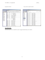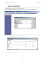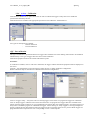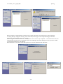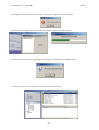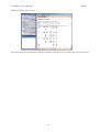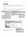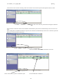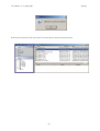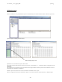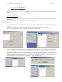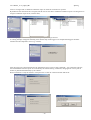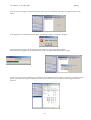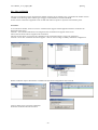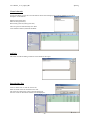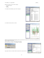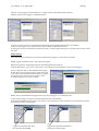
1
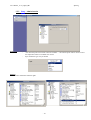
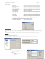
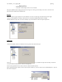
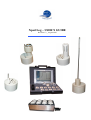
XpertLog – USER’S GUIDE
Revision 1.2 _ August 2007
User’s Manual _ rev 1.2_August_2007
1
2
3
4
XpertLog
Introduction
3
1.1
1.2
1.3
3
4
5
Introduction
Concept
Advantages
XpertLog Equipment
6
2.1
2.2
2.3
2.4
6
6
6
7
Hardware equipment
Different XpertLog Models
Minimal Configuration of XpertLog Validation System
Hardware configuration
XpertLog Software
8
3.1
Software installation and starting
Install XpertLog
Uninstall XpertLog
Start XpertLog
3.2
Main Menu
3.2.1.
Setup - Equipment Configuration
Equipment
Equipment Connections Verification:
Reference Probe
3.2.2.
Setup - Administration
3.2.3.
Setup - Calibration / Verification Configuration
3.2.4.
Setup - F Value Configuration
3.2.5.
Action – Equipment Info
3.2.6.
Action – Calibration
Off – line calibration
On – line calibration
Calibration reports
Save calibration reports
Export calibration report
Import calibration report
Delete calibration report
3.2.7.
Action – Verification
Off – line verification
On – line verification
3.2.8.
Action – Test
On – line test
F Value configuration
Test configuration
Start on-line test by time
Virtual channels
Add info
Start On-line Test
Off – line test
Data retrieve
Compile data from loggers
Create new report and define start and stop time
Test
- Report
- Trend
3.2.9.
Battery change SOP
8
8
9
10
11
12
12
13
13
14
18
20
22
23
23
27
30
31
32
32
33
34
34
37
39
39
40
40
41
42
42
42
45
46
49
50
51
51
51
52
XpertLog Technical Specifications
53
4.1
XpertLog - Thermal Validation System Uncertainty
4.2
XpertLog - Technical Specifications
Factory recommended recalibration interval
4.3
Temperature standard
4.4
Temperature block
53
54
54
55
56
-2-
User’s Manual _ rev 1.2_August_2007
1
Introduction
1.1
Introduction
XpertLog
XpertLog is a stand-alone thermal validation system that simplifies the entire validation process by significantly
reducing setup , minimizing sensor handling, and presenting critical study data in easily customized report
formats. This advanced system is specifically designed to conform with new FDA electronic records guidelines
(21 CFR Part 11) and meet international and European regulations for validation of pharmaceutical,
biotechnology and medical device (EN 285, EN 554, HTM 2010) ,manufacturing plants.
XpertLog is a portable instrument intended to be used throughout the facility on a routine basis.
XpertLog is the latest generation in Lives International’s line of thermal validation systems. It is composed by
wireless data loggers, easy and quick to program and to use for validation purpose or for day by day routine
testing. The loggers were designed specifically by Lives International to meet current thermal validation needs
and regulations. XpertLog can accommodate unlimited number of wireless data loggers; the sensor used for
temperature measurements is a 4-wire class B 1/10 DIN RTD.
Loggers programming and reading is accomplished through a Docking Station, a modular logger input interface.
The standard Docking Station has 4 loggers input channels. The temperature measurement range of wireless data
loggers is -50°C to 150°C. The system will be validated based on the temperature range available on customer's
site ( could be from -60 to 150°C), with a total system measurement accuracy of 0.1°C for all range of
measurement.
XpertLog System was designed to easily use for verification or calibration a temperature block or oil bath
manufactured by Lives International or Hart Scientific. This modular design allows for fully automatic sensor
verification or calibration, as well as multiple calibration or qualification equipment configurations.
Based on the use of high accurate RTD, the system does not requires calibration before running validation studies
but can use verification of specifications by the customer.
XpertLog software is designed to run on Windows 95,98, 2000, NT or XP and provides everything needed to
perform validation testing. Using XpertLog software, a system administrator creates user accounts and assigns
user IDs, passwords, and access permission levels that identify the person operating the instrument and prevent
unauthorized operation. Validation study setups, which include calibration criteria, are programmed using
XpertLog Software, and can be run in standalone mode or under PC control. The XpertLog also provides
encoded, secure data files that prevent modification of the original data, and includes data reporting options,
either as printed hardcopies or spreadsheet-compatible electronic files. This secure electronic data format is
designed to satisfy the requirements of 21 CFR Part 11 (Electronic Records and Signatures).
Internal memory of XpertLog data loggers contains 16,000.00 (sixteen thousands ) data points. XpertLog is
designed to write data to internal memory and PC hard drive (if connected) during sensor verification, calibration
and qualification.
Calibration, Verification and Qualification data is recorded to the internal memory in real time. Data loggers are
powered by a internal battery, which provides between 3 month and 1 year data logging.
XpertLog system is designed to operate with the Lives STS series temperature reference probes connected to
Lives ATC series temperature block, or Hart probe model 1502 or Kaye IRTD, and the Lives ATC series or Hart
temperature blocks or cryogenic oil bath.
The equipment provides NIST traceable calibration of thermocouples used in thermal validation studies, with a
range of -60°C to 150°C. During calibration and/or verification, XpertLog automatically reads and monitors the
temperature of the reference probe. For loggers calibration, the reference probe functions as the standard for
correcting thermocouple readings. The Temperature References provide highly stable temperature conditions for
sensor verification and/or calibration, and respond to pre-programmed calibration criteria, allowing automatic
loggers calibration at both low and high temperature set-points, with an optional third set-point for a mid-range
temperature check.
-3-
User’s Manual _ rev 1.2_August_2007
1.2
XpertLog
Concept
XpertLog is the latest generation in Lives International’s line of thermal validation systems. It is a compact,
modular, and portable data logger designed specifically by Lives International to meet current thermal validation
needs and regulations.
XpertLog software is designed to run on Windows 95,98, 2000, NT or XP and provides everything needed to
perform validation testing. Using the XpertLog software, a system administrator creates user accounts and
assigns user IDs, passwords, and access permission levels that identify the person operating the instrument and
prevent unauthorized operation. Validation study setups, which include calibration criteria, are programmed
using the XpertLog Software, and can be run in standalone mode or under PC control. The XpertLog also
provides for encoded, secure data files that prevent modification of the original data, and includes data reporting
options, either as printed hardcopies or spreadsheet-compatible electronic files. This secure electronic data
format is designed to satisfy the requirements of 21 CFR Part 11 (Electronic Records and Signatures).
Data loggers controlled by XpertLog have 16000 data points memory. XpertLog is designed to write data to
internal memory and then download the data in the data base in the computer.
XpertLog system is designed to operate with the Lives probe connected to the block, with Hart probe model 1502
and Kaye IRTD, and the Hart and Lives temperature blocks or cryogenic bath.
The equipment provides NIST traceable calibration of loggers used in thermal validation studies, with a range of
-50°C to 150°C. During calibration / verification, XpertLog automatically reads and monitors the temperature of
the reference probe. For loggers calibration or verification, the reference probe functions as the standard for
correcting loggers readings. The Temperature Reference provide highly stable temperature conditions for sensor
calibration, and respond to pre-programmed calibration criteria, allowing automatic loggers calibration at
unlimited temperature set-points, with an optional unlimited set-points for verifications.
-4-
User’s Manual _ rev 1.2_August_2007
1.3
-
-
-
XpertLog
Advantages
Security of data
Data logger serial number control operation
Pyramid operations:
- Calibrations
- Based on Calibration -> Tests
- Test
Minimize or eliminate calibration of loggers - factory accuracy is ± 0.1°C
Introduce the notion of verification only if necessarily
Reproducibility of results using completely automatic calibration
Security and access levels programmable by the system administrator
Electronic data protection and (FDA–21 CFR part 11)
Audit trails
Automatic operation for loggers calibration / verification
Calibration and test reports generated automatically
Display of data as values & trends
Introduce the concept of custom calculations
Available reports :
- Calibration reports
- Verification reports
- Test report :
- Temperature values
- F-values ( for penetration study )
- Statistics :
- Minimum values for each channel
- Maximum values for each channel
- Average values for each channel
Trends:
- Values
- The accumulated F-values
Intermediary reports during data
Minimum data acquisition interval = 1 sec.
Unlimited number of loggers to be programmed or read and stored in one report
Label configuration of each logger before test starting
Easy handling of loggers
Raw data recorded in the loggers memory - capacity of 16000 data points
Stand alone units
User friendly software
Flexible software
Software validation manual
One day training after delivery
IQ & OQ
Standard connectors and cables
Control of other manufacturers equipment : Hart temperature blocks and smart probe IRTD
-5-
User’s Manual _ rev 1.2_August_2007
2
XpertLog Equipment
2.1
Hardware equipment
XpertLog
XpertLog validation system is composed by:
Data loggers XpertLog
Temperature Reference Probe Lives (connected directly to the temperature block) or Hart probe with display
Temperature Block Lives
XpertLog validation software
PCMCIA card with 2 extra communication ports
Notice :
When the Lives temperature block (B series) is controlled through the Lives probe connected , it is strongly recommended
that the block and the probe be calibrated together by a Lives International calibration service.
The serial number of the probe must be entered in the block by the calibration service, together with the correction
coefficients for the probe. The verification of the equipment in the software allows users to be aware if the serial number
of the probe does not corresponds to the serial numbered recorded in the block.
Lives International declines all responsibility in case of incorrect use of probe connected to the temperature block.
2.2
Different XpertLog Models
Temperature
- RTD probe - case mount
- extended RTD probe – teflon coated ( 18 inch – 50 mm)
extended RTD probe – kapton coated ( 18 inch – 50 mm)
Ultra Low Temperature
High Temperature for Sterilization Tunnels
Temperature and Humidity
Temperature and Pressure
2.3
Minimal Configuration of XpertLog Validation System
Minimal configuration of XpertLog validation system:
Data Loggers Lives – XpertLog
Temperature Reference Probe Lives (connected directly to the temperature block) or Hart probe with display
Temperature Block Lives
XpertLog validation software
PCMCIA card with 2 or 4 communication ports
PC (laptop or desktop) with Pentium III processor 1.5 Ghz, 256 MB SDRAM, Hard Drive 20 Go,
OS: Windows 95/98 /NT / 2000 / Xp / Vista
-6-
User’s Manual _ rev 1.2_August_2007
XpertLog
WARNING
The computer to be used with the system needs to have a clean operating system and it is
recommended to be dedicated computer.
It is recommended to keep the computer clean of uncontrolled installations of other software
which could affect the normal operation of the system.
2.4
Hardware configuration
I
Configuring data loggers for Com port operations
Insert Lives data loggers in the docking station. Power on and connect the docking station to the computer using a null
modem cable.
The Baud rate is automatically chosen as 38000 baud
II
Programming the S/N of HART 1502 display
Connect the Probe to the module 1502A and power on the display
Set the baud rate:
• Press the “Menu” button ( “Set?” appears) then press the “K/Comm” button. The display will briefly indicate “Serial”
, then “bAud” and the display the current baud rate.
• Use the “Up” or “Down” arrows to increase or decrease the baud rate then press “Enter”. The nest parameter in the
“Comm” menu, the serial sample period, will then appear.
Start a new HyperTerminal session ( Comm 1; Bauds = 9600; Data = 8; Parity = None; Stop bit = 1; Flow control = none
then File –> Properties –> Parameters –> ASCII configuration –> check the 2 upper boxes in the window : - send EOF
and locally write the characters)
•
•
•
•
•
•
•
Enter the request *SN in order to display on the computer’s screen the serial number of the module.
Check the serial number displayed on the screen with the serial number physically labeled on the module.
If the serial number displayed is only the last three digits or it doesn’t corresponds with the serial number physically
labeled on the module then it has to be changed
Enter the following command in order to access the serial number modification: *PA=2051
Enter the serial number of the module *SN= xxxxxx
Enter the command *SN to display the serial number ; check if the serial number displayed is correct
Enter the command *PA=0 to lock the calibration menu.
III
Programming the PCMCIA communication card
Insert the PCMCIA communication card in the PCMCIA computer’s slot.
Follow Windows instructions for installing the card; use the driver provided by the manufacturer if available.
Verify in the Control panel that 2 (or 4 – depending upon the type of PCMCIA communication card available) extra COM
ports are available
IV
Connecting data loggers, reference probe and temperature block to the computer
Insert the PCMCIA communication card into the computer.
Start up the computer.
Connect docking station to Com 1 ( standard RS232 com port of the computer – when available)
Connect reference probe to one of available extra com port available
Connect temperature block to the other available com port available
-7-
User’s Manual _ rev 1.2_August_2007
3
XpertLog Software
3.1
Software installation and starting
XpertLog
Install XpertLog
Warning:
Before installing XpertLog software, disable screen savers of the computer and the “stop” of the hard disk during normal
operation of the PC.
Insert installation CD in the computer and double click on "Setup.exe"
After the Setup Box, follow the instructions displayed on the screen for choosing the directory in which XpertLog will be
installed.
-8-
User’s Manual _ rev 1.2_August_2007
XpertLog
Click on "Finish" to start the software; enter the name and the serial number; XpertLog icon is automatically placed on the
desktop
Warning: this is a case sensitive window, enter the name and the serial number as written on the CD's label.
Uninstall XpertLog
Insert the installation CD and double click on "Setup.exe" - follow the instructions displayed step by step
In order to completely uninstall the software the user needs to delete "XpertLog" folder from where it was installed.
In order to uninstall the software you can use "Add/Delete Software" in control panel – make sure the software is shut
down before uninstalling it.
-9-
User’s Manual _ rev 1.2_August_2007
XpertLog
Start XpertLog
.
Define a new data base, a new audit trail will be generated automatically.
XpertLog starts
First time when XpertLog starts the user will be logged on as Admin with no password required.
- 10 -
User’s Manual _ rev 1.2_August_2007
3.2
XpertLog
Main Menu
XpertLog is structured in modules, for a better understanding and simplicity of use. Select any module by clicking on the
appropriate button.
The structure of the software modules:
-
-
-
Setup :
-
Equipment
Administration
Calibration / Verification Configuration
F value configuration
-
Equipment Info
Calibration(when enabled)
Verification(when enabled)
Test
Import
-
Help
About
Exit
Action
Application
- 11 -
User’s Manual _ rev 1.2_August_2007
XpertLog
3.2.1. Setup - Equipment Configuration
Equipment
User has the ability of choosing the combination of equipment needed; click on "Equipment" then make your choice
-
Loggers: user needs to define the Com port for the loggers, communication speed is always
38000 baud.
-
Probe:
- Define com port
- Baud
- Type:
- IQ RTD
- Hart
- DTI - S1
- Lives Int.
- Lives Ext.
Number of digits: choose 3
-
-
Block:
- if the choice of the reference probe is Lives Int. or Ext. Then Block module is disabled ( the
block is controlled through the probe.
- If any other probe has been chosen, then user has the choice of the block : Hart or Lives.
- 12 -
User’s Manual _ rev 1.2_August_2007
XpertLog
Equipment Connections Verification:
After the configuration is ready, click on “Verify”. A dialog box will display the connection status between the data
loggers, the temperature standard, the temperature block and the computer.
For each equipment the system will display important information: identification; the serial number; the firmware version;
the communication port on which the equipment is connected; the engineering units.
Reference Probe
Different types of reference probes can be used for calibration:
-
IQ RTD - smart probe IRTD
Hart - reference probe from Hart
DTI - S1 - RTD from Ametek
Lives Int. - regulation probe of the Lives model ATC temperature block
Lives Ext. - reference probe Lives connected to front panel of the block Lives model B
The new concept introduced by XpertLog is the temperature block controlled by the reference probe when using Lives
probe and flexible wire data logger.
The minimum requirements in order to take advantage of this option is to use the reference block Lives ATC B Series.
This type of blocks have an external input for the Lives reference probe so this probe could be configured to control the
block: the regulations of the temperature block will be controlled by the reference probe.
Prior to operate this option you have to enable the option "Use external probe Lives block control if available" in "Admin"
module and then choose Lives External probe in the "Equipment Configuration".
- 13 -
User’s Manual _ rev 1.2_August_2007
XpertLog
3.2.2. Setup - Administration
Equipment:
-
"Use External probe Lives block control if available" : - the external probe will be used to control
the temperature block if a model B was chosen.
Style: define the type of style needed
Options:
Administration will define members rights
- 14 -
User’s Manual _ rev 1.2_August_2007
XpertLog
Options available:
-
delete tests:
double click and define the level allowed for the action
delete Verif and Calib:
double click and define the level allowed for the action
setup loggers:
double click and define the level allowed for the action
retrieve data from loggers:
double click and define the level allowed for the action
allow setup without retrieve:
enable or disable the option
create Off-line Tests:
double click and define the level allowed for the action
allow calibrations:
enable or disable the option
export/import tests:
double click and define the level allowed for the action
export/import verif and calib:
double click and define the level allowed for the action
create statistics:
double click and define the level allowed for the action
design reports:
double click and define the level allowed for the action
save reports:
double click and define the level allowed for the action
review reports:
double click and define the level allowed for the action
allow to review own reports:
enable or disable the option
show action hints:
enable or disable the option
logon required to end calib/verif/test and reset test:
enable or disable the option
activate battery replacement warning: enable or disable the option
activate calib date warning :
enable or disable the option
Security features:
"Allow setup without retrieve": if this option is enabled the loggers would be able to be programmed without retrieving the
data;
It is strongly advised to disable this option in order to avoid data destruction before retrieving data in the data base
Members:
Create new members on 4 different levels
The administrator has the ability to modify the password change interval and the password minimum length
Create a new member:
-
Click on the level needed to create new entry
Click on "New Member"
Define:
- Login
- Name ( enter full name)
- Password
- 15 -
User’s Manual _ rev 1.2_August_2007
-
XpertLog
- Retype password
Redefine the access level
Click Ok to acknowledge creation of new member
The option "Member must change password at next logon" is used to give the ability to the user to create his own
password when enabled by the administrator.
Database
Enable the option "Login required to use this database" in order to avoid usage of the data base with no login.
"Allow to select database on startup" will allow user to choose from different data bases available
"Backup database at app. Exit" will create a backup copy of the data base when closing the application
Audit Trail:
"Audit trail enabled" need to be enabled in order to generate the Audit trail report
Click on "Show Audit Report" in order to display the audit trail report ; the audit trail report has the ability to filter the
events for fulfill with administrator audit trail management.
Click on the right hand arrow in order to select or unselect all filter options.
After unselected all filter options, choose only the option needed e.g. "start test" then click on "Rebuild Report": only test
start will be displayed.
- 16 -
User’s Manual _ rev 1.2_August_2007
XpertLog
All options activated
Only "start test" option activated
Auto name format:
The default name for test or calibrations reports is suggested automatically by the software
- 17 -
User’s Manual _ rev 1.2_August_2007
XpertLog
3.2.3. Setup - Calibration / Verification Configuration
Loggers calibration:
Although the accuracy of the data loggers requests only annual calibration, the user might need to calibrate or verify data
loggers as many times as he wish; XpertLog will allow user to do so.
In order to run calibrations, the option “Allow calibrations” must be “On” in “Administration” –> “Options”
Two types of calibration / verification are available:
- Off Line Calibration
- On Line Calibration
For both types the configuration can be set by the user from this menu.
Calibration / Verification method
•
•
•
•
•
The calibration / verification is performed by comparing individual temperature values of each data logger to the
NIST (or COFRAC) independent temperature probe. A very accurate calibration can be performed if the RTD
probe and the calibration block/ bath are of the highest quality as specified by LIVES International.
XpertLog allows user to perform completely automatic hands free calibration by controlling data logger, reference
probe and temperature block / bath - the block / bath will automatically switch to calibration / verification set-points
as defined in the Calibration / Verification Configuration
In order to perform a reliable calibration, the calibration system must be very stable. The user’s entered value for
deviation from reference allowed defines the acceptable range of the actual temperature as compared to the set
temperature (calibration / verification temperature).
Unlimited number of calibration / verification set-points can be defined.
The stability of the system is defined as the value of the drift of the temperature allowed during the defined time for
drift. After calibration started, the RTD temperature value will be read and stored every second during “check time
for drift”. This is to make sure the drift defined by the user was respected. At any time, if the drift exceeds the limit,
the check time will be reseted. After the drift is within the limits defined by the user, the calibration will start.
After calibration was done the loggers are verified to confirm the corrected reading is within the user-specified logger
error allowed. This verification is performed for the duration of the check time for error and typically performed either at
the same temperature (for single-point calibration) or the middle point for the Low and High temperature (for two-point
calibration). Any logger which does not meet user-specified criteria of error allowed will be set OFF.
- 18 -
User’s Manual _ rev 1.2_August_2007
XpertLog
Calibration and Verification configuration:
Select “Calib. / Verif Config” in the main menu.
In order to add extra calibration / verification steps, right click on “Calibration” or “Verification” in the “Calibration
Config” window then “Add”
To modify the settings of the set point click on the specified set point and modify:
- temperature
- error allowed
- check time for error
by using the arrows next to each parameter.
In order to increase or decrease the value:
- by tenth - hold simultaneously “Ctrl” + “Shift” and click on the arrow (up or down)
- by units - hold only “Ctrl” and click on the arrow (up or down)
- by decimals - click on the arrow
Define the drift for the reference probe by clicking on “RTD & Block”.
- “Drift allowed” = drift allowed for the reference probe during “check time for drift”
- “Dev. From reference allowed” = drift will be checked starting the moment when the measured
temperature by the reference is within Set-point ± deviation allowed
- “Check time for drift” = drift will be verified for the time interval defined here
- 19 -
User’s Manual _ rev 1.2_August_2007
XpertLog
3.2.4. Setup - F Value Configuration
The module “F Config” will configure the calculation of the F value in the function of the test type: steam, dry heat with
or without depyrogenetion.
The instantaneous lethal rate (F-value) of a given steam sterilization cycle is the lethality at specified conditions and can be
calculated once the D-value and Z-value are known using the following algorithm:
F = 10(T0-Tb) /
Z
Where:
T0 = Temperature within the item being heated
Tb = Reference temperature
Z = Z-value of the challenge organism
For steam sterilization, the values typically used are Tb = 121.1°C and Z = 10°C. When these values are used, the F-value
is defined as the F0 value. The above equation is an exponential function and therefore as T0 increases, there is an
exponential increase in F0. Note that for F0, the instantaneous lethal rate at T0 = 121.1°C is F0 = 1 minute.
The sum of the instantaneous lethal rates over the course of a cycle yields the accumulated lethality delivered and is
calculated using the following algorithm:
F0 = ∑10(T – 121.1° C) / 10° C) ∆t
Where:
∆t = The chosen time interval in minutes
T = Average temperature over the ∆t interval in °C
To determine the log reduction achieved by the sterilization, the accumulated lethality is divided by the D-value as shown
in the following algorithm:
LR = F0/D
Where:
LR = Log reduction
F0 = The accumulated lethality using Tb = 121.1°C and Z = 10°C
D = The D-value of the microbial population
-
Choose the “F Config” module from the main menu.
Choose the study type (steam, dry heat with or without depyrogenetion).
Define the Z value and the reference temperature value for F calculation.
Define the minimum temperature from which the F Value will start accumulating
Click on “OK” to validate the choice of the parameters for F value calculation or “Cancel” for returning in the main
menu.
The F value calculation configuration may be defined or started from the main menu or started from any module
(calibration or test).
If the F configuration is done starting from the main menu the values will be considered as default values for the system.
If the F value configuration is done starting from another module the specified values will be available only for the active
test.
- 20 -
User’s Manual _ rev 1.2_August_2007
XpertLog
The F value used to evaluate the efficiency of a sterilization process is the time necessary to produce a certain sterilization
effect.
F value is defined as the time (in minutes) to produce the equivalent sterilization effect at 121.1 °C (250 °F).
Z value is defined as the temperature change in °C required to cause a one-log reduction in the D-value.
D-value is the measure of the relative heat resistance of an organism at a constant temperature.
The most commonly used value of Z for the destruction of microbial spores is 10°C (18°F). This is based on experimental
observations for Baccilus Geostearothermophilus – a highly heat resistant organism.
- 21 -
User’s Manual _ rev 1.2_August_2007
XpertLog
3.2.5. Action – Equipment Info
XpertLog is based on a equipment information templates system, which allows the user to define and store all types of
equipment with specific description ,serial number, location etc…
The equipment information will then be stored in the header of the test corresponding to the equipment.
Click on Listing to display the report of all equipment defined.
Close the window to return to main menu.
- 22 -
User’s Manual _ rev 1.2_August_2007
XpertLog
3.2.6. Action – Calibration
Calibration was defined as an option for the user in order to calibrate the loggers if they came to be outside the
specifications defined by the user.
Calibration menu is available if the appropriate option have been enabled in “Administration”.
XpertLog can accommodate up to 20 sensor inputs, in any combination of thermocouples, PT100, thermistors, voltages or
current inputs.
Choose the type of sensor connected on the data logger.
Correction coefficients are disabled for Tc configuration and are enabled for other types of sensors ( 4-20 mA, 0-1 V
etc…).
Two types of calibration are available:
- Off line calibration
- On line calibration
Off – line calibration
This type of calibration is performed when more loggers then available slots in the docking station need to be calibrated
simultaneously or the type of loggers does not allow on-line calibration.
Calibration equipment used will be oil bath and reference probe.
Procedure:
In "Calibration" module, click on "Off–line" calibration; the loggers and the calibration equipment used are displayed on
the screen.
Click Ok – the configuration screen will appear to allow the user to change calibration configuration.
Define calibration steps as described in “Calibration/Verification Configuration”
Click on “Loggers setup” – the system will scan existing loggers in the station. To program the loggers for calibration
click on “Setup Loggers” and then remove them from the station. To program more loggers then slots available in the
station insert the loggers which are not yet programmed in the station then click “Refresh loggers” and “Setup loggers” as
many times as needed to program for calibration all loggers. When clicking on “Setup loggers” a warning message will
appear to inform the user that all data stored in the logger will be overwritten; choose Yes to proceed. When loggers are
programmed for data acquisition the icon corresponding is clock + blank ampoule.
- 23 -
User’s Manual _ rev 1.2_August_2007
XpertLog
When all loggers are programmed for calibration remove them all from the station and click on “Step Completed”.
A warning message will appear informing users that the setup of the loggers was completed and loggers should be
transferred to the temperature source (e.g. oil bath).
After the loggers have been transferred to the temperature source click on “Step completed” – the calibration will start; the
oil bath and the reference probe are controlled by the software during calibration; changing from one set-point to another
is performed automatically by the software.
When calibration is ready the software will request user to enter the calibration name and hit Ok.
- 24 -
User’s Manual _ rev 1.2_August_2007
XpertLog
If the loggers have not been placed in the reader, the message “Loggers not found” will appear.
In this case place the loggers in the reader and click “Refresh Loggers” and “Retrieve data”.
After data from all loggers were downloaded, the message “All required data downloaded” appears
. Click Ok, close then open “Calibration” to see the list of calibration reports.
- 25 -
User’s Manual _ rev 1.2_August_2007
XpertLog
Double click on the report to open it.
The report will display the temperature value of the reference probe and the error of each logger versus the reference.
- 26 -
User’s Manual _ rev 1.2_August_2007
XpertLog
On – line calibration
This type of calibration can be used when the number of loggers to be calibrated is less or equal then the number of slots
available on the docking station and the type of loggers to be calibrated is flexible RTD.
In this case the calibration equipment can be oil bath and reference probe or dry block and reference probe.
Procedure:
In "Calibration" module, click on "On–line" calibration; the loggers and the equipment used for calibration are displayed
on the screen.
Click Ok – the on line calibration screen will appear - click on "Calib Config" to modify calibration configuration.
Define calibration steps as described in “Calibration/Verification Configuration”
In order to visualize calibration configuration bring the mouse on "Calib Config" - calibration configuration will be
displayed at screen.
Click on "Start Calib" in order to start calibration.
Enter the name of the calibration report and hit Ok.
Calibration will start.
- 27 -
User’s Manual _ rev 1.2_August_2007
XpertLog
Calibration will start with first checking stable environment for the reference probe and temperature block or bath.
Checking the drift of the reference probe before starting the calibration
Once the drift is stable the software will read data at the defined set-point, then will automatically switch to the next setpoint.
After reading data in all defined calibration set-points, the software will automatically switch to the verification point and
display the corrected values in that point.
Calibration at 90°C: data shown is data before correction
Click on Ok to finish the On-line calibration.
Value of the reference probe in verification point
Corrected data after calibration
- 28 -
User’s Manual _ rev 1.2_August_2007
XpertLog
Double click on the name of the report in the list of the reports to open the calibration report.
- 29 -
User’s Manual _ rev 1.2_August_2007
XpertLog
Calibration reports
After the calibration was performed the report will automatically be created and stored in the calibration report list.
Open the report to display calibration data.
Click to enlarge report view
By default view of calibration report is data values.
The header contains data about the license used, version, serial number etc..., comments and the configuration of the
calibration.
The calibration report will show the errors between each logger and the reference probe before and after correction.
Trends are also available for calibration.
Add info option will allow user to insert comments in the header of the report.
Remove a logger from the report: disable the logger to be removed from the report and click on “Rebuilt report”
- 30 -
User’s Manual _ rev 1.2_August_2007
XpertLog
Save calibration reports
Calibration reports can be stored in different formats by the user.
1° pdf
-
click on “disc” icon to save the report
choose the path to store the report C:
choose the type of report : “ Adobe Acrobat Document.pdf”
enter for the name of the file
in the “PDF Export Options” choose
“Export Image Format” as JPG
disable “Export Frames”
click Ok
-
click on “X” icon to save report as Excel file
choose the path to store the report C:
do not change the type of the report (Excel Files (*.xls)
enter for the name of the file
Excel will automatically open the report as a Excel file
2° xls
Using the same procedure user can save reports also as:
-
report file (*.frp)
text file (*.txt)
rich text file ( *.rtf)
html file (*.htm)
csv file (*.csv)
bitmap file (*.bmp)
- 31 -
User’s Manual _ rev 1.2_August_2007
XpertLog
Export calibration report
Close then right click on the calibration report. The options “delete”, “export” and “linked objects” will be visible.
Click on “Export” in order to export the calibration report. Define the location where to store the calibration report by
clicking on the small icon next to the path.
Define location
Calibration report to be exported will be displayed with all its extensions – user may enable or not the saved calibrations in
order to be exported with the original calibration report.
Click on “Export” in order to store the calibration report in the defined location. After the export was effective the “Export
completed” window will be displayed.
Import calibration report
The calibration report can not be imported in the same data base from where it was exported.
User can only import it in the different data base.
In order to import a calibration report, return to main menu then in “Action” click on “Import”. All the available reports
for import will be displayed.
Choose and double click on the calibration report you want to import then click on “Import”.
Close the window.
The calibration report will be imported in the data base.
Close the window and open “Calibration” menu. The imported calibration report is added to the list of calibration reports
with a small “I” red icon
- 32 -
User’s Manual _ rev 1.2_August_2007
XpertLog
Delete calibration report
Right click on the calibration report. The options “delete”, “export” and “linked objects” will be visible.
Click on “Delete” in order to delete the calibration report. A comment window will appear to request a comment enter
before deletion of the report. Click Yes to delete the report.
Open the audit trail and check the comment was added.
- 33 -
User’s Manual _ rev 1.2_August_2007
XpertLog
3.2.7. Action – Verification
Verification is used by user in order to verify, if needed, if the specifications of the loggers are within the specifications
defined.
Two types of verifications are available: on line and off line.
Off – line verification
This type of verification is performed when more loggers then available slots in the docking station need to be verified
simultaneously.
Calibration equipment used will be the oil bath and the reference probe.
Procedure:
In "Verification" module, click on "Off–line Verif"; the loggers and the equipment used for verification are displayed on
the screen.
Click Ok – the configuration screen will appear to allow the user to change verification configuration.
Define verification steps as described in “Calibration/Verification Configuration”
Click on “Loggers setup” – the system will scan existing loggers in the station. To program the loggers for verification
click on “Setup Loggers” and then remove them from the station. To program more loggers then slots available in the
station insert the loggers which are not yet programmed in the station then click “Refresh loggers” and “Setup loggers” as
many times as needed to program for verification all loggers. When clicking on “Setup loggers” a warning message will
appear to inform the user that all data stored in the logger will be overwritten; choose Yes to proceed. When loggers are
programmed for data acquisition the icon corresponding is "clock + blank ampoule".
- 34 -
User’s Manual _ rev 1.2_August_2007
XpertLog
Click on "Assign Calib" to define the calibration report to whom the verification is reported.
By default the last calibration file is assigned, but the user has the choice of different calibration report to be assigned or to
assign no calibration report at all ( without calib.)
After assigning the calibration report click on "Step completed" to go forward.
A warning message will appear informing users that the setup of the loggers was completed and loggers should be
transferred to the temperature source (e.g. oil bath).
After the loggers have been transferred to the temperature source click on “Step completed” – the verification will start;
the oil bath and the reference probe are controlled by the software during verification; changing from one set-point to
another is performed automatically by the software.
When verification is ready the software will request user to enter the verification name and hit Ok.
- 35 -
User’s Manual _ rev 1.2_August_2007
XpertLog
Insert the first set of loggers in the docking station and click Ok; the software will search for loggers presents in the
station.
If the loggers have not been placed in the reader, the message “Loggers not found” will appear.
In this case place the loggers in the reader and click “Refresh Loggers” and “Retrieve data”.
After data from all loggers were downloaded, the message “All required data downloaded” appears
Click Ok, close then open “Verification” to refresh the list of calibration reports. Double click on the verification report to
open it. The report will display the temperature value of the reference probe and the error of each logger versus the
reference.
- 36 -
User’s Manual _ rev 1.2_August_2007
XpertLog
On – line verification
This type of verification can be used when the number of loggers to be verified is less or equal then the number of slots
available on the docking station and the type of loggers to be calibrated is with flexible RTD.
In this case the verification equipment can be oil bath with reference probe or dry block with reference probe.
Procedure:
In "Verification" module, click on "On–line" verification; the loggers and the equipment used for verification are
displayed on the screen.
Click Ok – the available calibrations to be assigned to the verifications will appear on the screen.
Choose the one which will be assigned to the verification.
The user has the choice not to assign any calibration to the verification which is going to be performed.
Click Ok - the on line verification screen will appear - click on "Verif Config" to modify verification configuration.
Define verification steps as described in “Calibration/Verification Configuration” then click Ok.
Click on "Start Verif" to start the verification.
Name the verification then hit Ok button.
- 37 -
User’s Manual _ rev 1.2_August_2007
XpertLog
The verification will start; drift will be first verified; once the drift was verified
and found within the specifications defined by the user, the calibration will start.
When on-line verification is ready the message "Verification successfully completed" will appear.
Click Ok in order to save the verification report.
Click Ok, close then open “Verification” to refresh the list of calibration reports. Double click on the verification report to
open it. The report will display the temperature value of the reference probe and the error of each logger versus the
reference.
- 38 -
User’s Manual _ rev 1.2_August_2007
XpertLog
3.2.8. Action – Test
Test menu is used to program loggers for acquisition and to download data from loggers after the tests.
Two types of test are available:
- On-line tests
- Off-line tests
On – line test
In "Test" menu, click on "On-line Test" to start a new on-line test. The software will search for loggers available and
display them.
Click Ok - software will display the calibration reports available for each logger; user can use any calibration report
available or use no calibration report at all. By default the last calibration report will be available.
Click Ok to go to next step.
User may configure
- the F value
- acquisition interval
- virtual channels
- add info.
- 39 -
User’s Manual _ rev 1.2_August_2007
XpertLog
F Value configuration
Click on "F Config" to define the type of test and define if F value will be or not calculated.
Right click on the screen to select or unselect all channels or enable one by one the cases corresponding to the loggers to
be enabled.
Click on "Config" to define the type of sterilization: steam, dry heat with or without depyrogenation.
Test configuration
Click on "Test Config" to define the acquisition interval, start by time or by value.
Define loggers data acquisition interval;
- 40 -
User’s Manual _ rev 1.2_August_2007
XpertLog
Start on-line test by time
Click on "By time" and define start and stop time.
This feature is valid only for on-line tests.
Click on "Start Test" and enter the name of the test.
The loggers will switch to idle, data will be displayed on the screen but not stored in the report till the time defined by the
user.
Then loggers will switch to "data collect" and start collecting data in the report.
When stop time defined by the user is achieved, the test will automatically stop.
Close and open test to refresh tests list and display the report which was performed.
- 41 -
User’s Manual _ rev 1.2_August_2007
XpertLog
Virtual channels
Use has the ability to insert his own calculations which will be displayed as separate channels in test report.
Examples of calculations:
Maxval=max(@234:265);
MinVal=min(@234:265);
Delta=max(@234:265)-min(@234:265)
The test report will automatically have three
extra channels: MaxVal, MinVal and Delta.
Add info
This menu is used for adding comments in the header of the report
Start On-line Test
Click on "Start Test" to start the on-line test.
Enter the name of the test and click Ok to start.
The values for each logger will be real time displayed.
Also the values for the virtual channels will be displayed .
- 42 -
User’s Manual _ rev 1.2_August_2007
XpertLog
During the on-line test user is able to display:
- intermediary report
- trends
- statistics
To visualize the intermediary report click on "Report"
To visualize the trends click on "Trend"
Statistics are calculated from the beginning of the test to the first reset, between two consecutive resets and between the
last reset and the end of the test.
Click on "Reset" to reset the test and create new statistics.
Warning message will appear - acknowledge to go further.
Open again statistics to visualize statistics from the start of the test to reset.
- 43 -
User’s Manual _ rev 1.2_August_2007
XpertLog
To stop the test click right upper corner.
- 44 -
User’s Manual _ rev 1.2_August_2007
XpertLog
Off – line test
This is the most common usage of XpertLog data loggers.
Click on "Logger Prepare" to define start time, stop time and data acquisition interval.
The software will search for existing loggers in the docking station.
Define
- Start Time
- Stop Time
- Interval
then Setup loggers for acquisition.
Interval can be from 01 sec to 23:59:59 hours
If any calibrations available, the user can
choose the one he needs. By default the last
calibration is displayed.
Double click to choose a calibration file.
User can choose no calibration at all.
.
- 45 -
User’s Manual _ rev 1.2_August_2007
XpertLog
Click Ok to setup loggers for data acquisition. Loggers will be setup and start data collection.
Memory capacity of the loggers is 16000 data points.
Loggers can now be taken out from the station and placed in the equipment which need to be validated.
At any moment loggers can be replaced in the station and data read from the memory.
If the loggers have been read before stop time, they keep on collecting data until the user will place them on idle or until
stop time.
Data retrieve
After data have been collected, user can retrieve data from the loggers; several cases are possible:
Case 1: loggers reached stop time - data collection stopped
Replace the loggers in the docking station for downloading data from memory.
From the main menu - go in "Test" - data retrieve - the software will automatically scan for existing loggers.
Click on "Retrieve data" to download data from loggers.
If data need to be retrieved from more loggers then slots
in the station, download data from the first set of loggers
then replace then with the next set of loggers, click
on "Refresh loggers" then "Retrieve data"
Case 2: data is downloaded from loggers before stop time and logger is not switched to idle
In this case the loggers will keep on collecting data after data is downloaded.
If the data downloaded from the loggers was saved in a test report then it will be impossible to download the rest of the
data from the memory of the loggers.
Loggers are collecting data, data
have not been downloaded
- 46 Loggers have been downloaded and
still keep on collecting data
User’s Manual _ rev 1.2_August_2007
XpertLog
If the user will refresh loggers and retrieve data the software will warn the user that the logger has more recent data than in
data base and will ask the user to replace existing data.
If acknowledged, the software will download all data from the memory of the loggers and still keep on collecting data, as
they are not in idle.
If the user would close the window and go in test compile to store the data from the loggers, the data will be saved as a
report.
Enter the name of the report, report will be saved.
Return to “Loggers prepare” ; the software will scan the station to find and display available loggers. The icon
corresponding to the loggers will be “blue i”
- 47 -
User’s Manual _ rev 1.2_August_2007
XpertLog
Refresh loggers and retrieve data from the available loggers.
As the loggers have more recent data then existing in the data base,
the software will try to recover all data.
Acknowledge to recover data.
Data can not be stored in the data base because
part of data from the loggers have been saved
in a test.
Case 3: data is downloaded from loggers before stop time and logger is switched to idle
If user want to download data before stop time, he will need to stop the loggers and retrieve data.
Refresh loggers then click on the first logger in the list; click then on “switch to idle” to stop collecting data
Loggers are collecting data, data
have not been downloaded
- 48 -
User’s Manual _ rev 1.2_August_2007
XpertLog
Compile data from loggers
After data has been downloaded, they need to be organized in reports.
XpertLog allow users to organize data in reports.
In order to do this user needs to open “Test compile”
Data downloaded from the loggers are organized by
- start time
- download time
- logger
- setup by
- by tests
Click on start time to visualize data
that user can choose from
If the start time is not known use “download time” to choose data for report.
- 49 -
User’s Manual _ rev 1.2_August_2007
XpertLog
In order to choose the data for report right click on the logger which contains this data and enable “Use”.
If data from several loggers are needed, right click on the date and time corresponding to this loggers in download time.
Enable to retreive
data from single
logger
Enable to retreive
data from several
loggers
Create new report and define start and stop time
Once the loggers have been choosed, the options in “Views” menu are enabled and the user can visualize data to be stored
in the report.
Click on “Grid” to see all data from the loggers defined previously.
In order to define a specific start time set the cursor on the date and time which will be defined as “Start time”, right click
there and enable the option “Mark Report Start”
The report will start then from that specific data point; to define the “Stop Time” define similar configuration except you
have to move the cursor on the stop time date and time, right click and enable “Mark report end”
- 50 -
User’s Manual _ rev 1.2_August_2007
XpertLog
Save the report by clicking on “Save” in “Action” – name the report then click Ok. The report will be added at the test list
Save the report
Test
- Report
Open a report from test reports list.
Data points will be displayed as a test report on screen; the report will have all the information needed by the user in the
header:
- name of the test report
- comments inserted by the user
- equipment information
- F configuration information
- all the calculations defined by the user in “Virtual channels”
- Trend
In the report click on “Trend”
The trends will be displayed at screen; to enlarge click
on the dots next to the trend
- 51 -
User’s Manual _ rev 1.2_August_2007
XpertLog
3.2.9. Battery change SOP
This section describes the procedure of changing the batteries for all types of XpertLog data loggers.
In order to perform this operation, make sure you have available:
- tool for opening the loggers
- silicon grease
- batteries
- o-rings for the loggers
- loggers
Operating procedure:
-
use the tool to block the lower part of the logger and unscrew the upper part
take off the battery from the logger
take off the o-ring
clean-up the thread
replace the new o-ring
place the new battery inside the logger in the battery supports
lubricate the thread using the silicon grease
close the logger by screwing the lower part on the upper part
use the tool to block only the superior part of the logger and thread the lower part by hand only till the end.
clean up the silicon grease
place the logger in the docking station and test the communication with the software
start the software and log on as an administrator using Id and password
go in “Equipment” and click on “Verify”
click on the button “Config”
enter the date of replacement of the battery, battery replacement interval and the alert in advance interval
click Ok to exit
in order to automatically be warned by the software about change date of the battery, go in “Administration”
open “Options” and enable “Activate Battery Replacement”
- 52 -
User’s Manual _ rev 1.2_August_2007
XpertLog
4
XpertLog Technical Specifications
4.1
XpertLog - Thermal Validation System Uncertainty
Uncertainty calculation - XpertLog System
XpertLog Data Loggers uncertainty under worst case
Temperature (°C)
Calibration Uncertainty at k=1 (±°C)
Calibration Uncertainty at k=2 (±
±°C)
-38
0,00798
0,01596
0
0,00915
0,01830
121
0,01304
0,02608
Please contact factory for detailed calculations.
- 53 -
User’s Manual _ rev 1.2_August_2007
4.2
XpertLog
XpertLog - Technical Specifications
Technical Specifications:
Loggers :
Temperature
Pressure
Humidity
PT-100, 4 wires
High accuracy : 0 à 5 bar absolute
Capacity
Specific applications :
Range :
& accuracy
- Temperature
-60 à +150°C (continuous)
-80 à +100 °C (continuous)
Extremes:
no shield:
± 0.1°C
± 0.1°C
+ 175°C
(limited time)
with shield
- 110 °C
___________________________+ 340 °C
- Pressure
0 à 5 bar absolute
± 5 mbar
20 à 90 %RH
± 2 %RH
- Humidity
Material :
Ketron Peek –FDA compliant
Battery
Lithium, user replaceable
Leak free
IP-68
Data collection interval
1 second to 24 hours
Memory
16 000 data points
Internal watch accuracy
< 1 second / month
Weight
35, 40 or 70 g (battery included)
Calibration
COFRAC / NIST traceable
ITS-90 coefficients included
Factory recommended re-calibration interval
Temperature and pressure loggers:
Humidity loggers:
12 month
6 month
- 54 -
1°: -80°C freezers : continuous
operation @ -80°C for one week
cycles - no thermal shield needed
2°: sterilisation tunnels: standard
operation at up to 340°C for 10
minutes – requires thermal shield
and standard cooling zone – does
not apply to heat ovens (250°C for
several hours)
USB Docking Station :
High speed communication
Customizable : 4, 8, 12, 20
- Reduced dimensions
- Simultaneously programming
of unlimited number of loggers
User’s Manual _ rev 1.2_August_2007
4.3
XpertLog
Temperature Reference Probe
Temperature display:
Technical specifications:
-
Resistance :
Temperature range :
Material:
Hysteresis
Accuracy:
100 ohm nominal ± 0.1 ohm à 0°C
-200 à 500 °C
inconel
< 0,01 °C à 0°C with extremely points –183 et 420 °C
± 0,018 °C @ -196°C
- ± 0,018 °C @ 0°C
- ± 0,019°C @ 200°C
- ± 0,023°C @ 420°C
-
Dimensions:
-
Model:
Type 5612:
Type 5613:
Type 5614:
HART
0,187 " dia. x 9 " ( 0,475 x 22,86 cm)
0,187 " dia. x 6 " ( 0,475 x 15,24 cm)
0,25 " dia x 12 " ( 0,635 x 30,48 cm)
Reference probe:
- Temperature range:
- Resistance range:
- Probe:
- Parameters:
- Accuracy:
-200 à 650 °C
0 to 400 ohm
25 or 100 ohm
ITTS-90, IPTS-68 or Calendar-Van Dusen
± 0,006°C @ 0°C
± 0,009°C @ 100°C
- ± 0,012°C @ 200°C
- ± 0,018°C @ 400°C
- ± 0,024°C @ 600°C
- Temperature coefficient:
- Temperature resolution:
- Resistance resolution:
- Calibration:
<0,5 ppm/°C,
0,001°C
0,0001 ohm
The coefficients are corrected in the equipment during the annual calibration. The
formulas for ITS – 90 are stored in the thermometer’s firmware.
The display shows the real temperature
8 digit, 7 segments LED
14,3 x 18,1 x 6,1 cm
1 Kg
HART
- Display:
- Dimensions:
- Weight:
- Type:
SOFTWARE for reference probe:
The RTD Thermo software of LIVES International allowes:
-
Display up to 9 reference probes in the same time (HART probe or intelligent probe IRTD)
Trace the report under EXCEL with the continuously record of the 9 probes
Useful for the probes calibrations in the field
- 55 -
User’s Manual _ rev 1.2_August_2007
4.4
XpertLog
Temperature blocks
LIVES ATC-125; ATC-140; ATC-156; ATC-320;
ATC-650
. Fast calibration due to special design of the block, and no use of liquids
. Ensures correct calibration with built-in automated functions
. A large and clear, easy to read multi information display
Range of temperatures: from –90
°C to 650 °C
LIVES Series temperature blocks in pharmaceutical
process.
Traceable, simple and fast.
Specifications
Units
ATC-125
A
Temperature range:
min
max
ATC-157
B
A
°C
°C
Well diameter
mm
Well depth
mm
Accuracy
°C
Stability
°C
Axial Homogeneity (40 mm)
°C
Radial homogeneity (between borings °C
0.01 °C
Stability indicator
Max resolution
°C
0.01 °C
Heating time ambient temp to 125°C
min
20
Cooling time ambient to -80°C
min
70
Heating time ambient temp to 100°C
min
23
Cooling time 100°C to ambient
min
6
Automatic switch test
Programmable slope rate
°C/min
Auto - step
Line voltage
VAC/Hz
Dimensions
length
mm
506
height
mm
448
width
mm
200
Weight
Kg / lb
20 / 44,1
13.1 / 28.9
FPSC
Yes
Dual Peltier zone
Yes
Dual heating zone
Yes
Yes
MVI circuit for protection against power supply voltage variations
Protection class
IP
CE labeling
CE
-90°C
125°C
30 mm
185 mm
0.3°C 0.06°C
0.03 °C
ATC-156
B
A
B
ATC-320
A
B
-45°C
-25°C
25°C
155°C
155°C
320°C
20 mm
30 mm
30 mm
150 mm
150 mm
160 mm
0.19°C 0.04°C 0.19°C 0.04°C 0.26°C 0.07°C
0.02 °C
0.02 °C
0.02 °C
0.05 °C
0.05 °C
0.05
0.02 °C
0.02 °C
0.01
Yes - User programmable
0.01 °C
0.01 °C
0.01 °C
- 56 -
ATC-650
A
B
25°C
650 °C
30 mm
160 mm
0.39°C 0.11°C
0.03 °C
0.1
0.05
0.01 °C
23
7
27
22
43
Yes - Open , Close , Hysteresis
0,1 to 9,9
Yes - up to 10 steps
230/50 -60 or 115 /50 -60
352
156
360
12.2 / 26.9
10.1 / 22.5
12.1 / 26.7
9
Yes
10
Yes
Yes
Yes
User’s Manual _ rev 1.2_August_2007
XpertLog
- 57 -