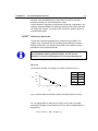
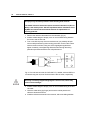
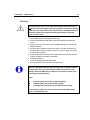
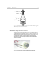
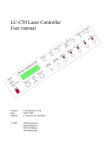
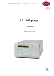
1
FLEXCELL
TM
user manual
Antec .... Proven Performance!
102.0010A, Edition 7, 2009
Antec Leyden bv, Industrieweg 12, 2382 NV Zoeterwoude, The Netherlands
Phone: +31 71 5813333 ● fax: +31 71 5813334 ● [email protected] ● www.myantec.com
INTRODUCTION
Table of contents
1
Copyright ©2008 Antec Leyden. All rights reserved. Contents of this publication may not be
reproduced in any form or by any means (including electronic storage and retrieval or translation
into a foreign language) without prior agreement and written consent from the copyright of the
owner. The information contained in this document is subject to change without notice.
DECADE II, DECADE, INTRO, Sencell, Flexcell, Reactor, ISAAC, HyREF, LINK, ADF, DECADE
Dialogue, DECADE II Dialogue are trademarks of Antec Leyden BV. Whatman™ (word and
device) and Whatman™ (word only) are trademarks of Whatman lnternational Ltd. SOLVENT
®
®
IFD™ and AQUEOUS IFD™ are trademarks of Arbor Technologies, Inc. Clarity , DataApex are
®
trademarks of DataApex Ltd. Microsoft and Windows™ are trademarks of Microsoft Corporation.
The information provided herein is believed to be reliable. Antec Leyden shall not be liable for
errors contained herein or for incidental or consequential damages in connection with the
furnishing, performance, or use of this manual. All use of the hardware or software shall be entirely
at the user’s own risk.
2
Flexcell manual, edition 7
INTRODUCTION
Table of contents
3
WEEE directive
All equipment of Antec Leyden which are subjected to the WEEE directive
shipped after August 13, 2005 are compliant with the WEEE marking
requirements. Such products are labelled with the “crossed out wheelie”,
depicted on the left site.
The symbol on the product indicates that the product must not be
disposed as unsorted municipality waste.
Collection & recycling information
Please ship the part back to the manufacturer (Antec Leyden, the
Netherlands) at the end-of-life time of the product. The manufacturer will
take care of the proper disposal and recycling of the instrument at its
facilities.
Shipping address for the end-of-life products:
Antec Leyden
Industrieweg 12
2382NV Zoeterwoude
The Netherlands
In case of questions, or if further information is required about the collection &
recycling procedure, please contact your local distributor.
ROHS directive
Our instruments are currently exempt from the RoHS directive because they
fall under WEEE Annex IA categories 8 and 9, which includes medical
devices and monitoring and control instruments. Nevertheless, we have taken
steps to eliminate all restricted substances from our products.
Intended use
For research purposes only. While clinical applications may be shown, this
instrument /part is not tested by the manufacturer to comply with the In Vitro
Diagnostics Directive.
Antec Leyden is an ISO 9001:2000 certified company.
4
Flexcell manual, edition 7
Symbols
The following pictograms are used in this user manual:
Warning/caution sign. It calls attention to a procedure or practice which, if not
adhered to, could result in severe injury or damage to parts or all of the
equipment. Do not proceed beyond a warning sign until the indicated
conditions are fully understood and met.
The attention sign signals relevant information. Read this information, as it
might be helpful.
The note sign signals additional information. It provides advice or a
suggestion that may support you in using the equipment.
INTRODUCTION
Table of contents
5
Safety practices
Perform periodic leak checks on LC tubing and cell connections. Do not allow
flammable and/or toxic solvents to accumulate. Follow a regulated, approved
waste disposal program. Never dispose of such products through the
municipal sewage system.
LC equipments should be used by trained laboratory personnel only.
Use proper eye and skin protection when working with solvents.
Additional safety requirements or protection may be necessary
depending on the chemicals used in combination with this equipment.
Make sure that you understand the hazards associated with the
chemicals used and take appropriate measures with regards to safety
and protection.
Use of this product outside the scope of this guide may present
a hazard and can lead to personal injury.
Spare parts and service availability
Manufacturer provides operational spare parts of the instrument and current
accessories for a period of five years after shipment of the final production run
of the instrument. Spare parts will be available after this five years period on
an ‘as available’ basis.
Manufacturer provides a variety of services to support her customers after
warranty expiration. Repair service can be provided on a time and material
basis. Contact your local supplier for servicing. Technical support and training
can be provided by qualified chemists on both contractual or as-needed
basis.
6
Flexcell manual, edition 7
INTRODUCTION
Table of contents
Table of contents
I N T R O D U C T I O N
WEEE directive 3
ROHS directive 3
Intended use 3
Symbols 4
Safety practices 5
Spare parts and service availability 5
Table of contents 7
The electrochemical flow cell 9
Introduction 9
Three-electrode configuration 10
HyREF™ reference electrode 11
I/E curves 11
Example 12
ISAAC™ reference electrode 12
Salt bridge Ag/AgCl reference electrode 14
Working electrodes 14
Installation 17
General precautions 17
Installation of Flexcell 17
Maintenance 21
HyREF & ISAAC 21
Ag/AgCl salt bridge 21
Saturation and air bubbles 21
Material 22
Procedure 22
Maintenance of the cotton wool frit 23
Working electrode maintenance 25
Decreased flow cell performance 25
Disassembly of the flow cell 26
Polishing 27
Assembly of the flow cell 28
Maintenance Magic Diamond electrode 29
Storage 31
7
8
Flexcell manual, edition 7
CHAPTER 1
The electrochemical flow cell
C H A P T E R
1
The electrochemical flow cell
Introduction
The Flexcell™ has been developed for analysis in standard and microbore
LC-EC. The use of an exchangeable working electrode offers maximum
flexibility for multiple applications requiring different working electrode
materials. Also in applications where the working electrode material is
electrochemically ‘consumed’ this is advantageous. Exchanging the working
electrode only takes a minute. The Flexcell has an effective volume of 0.5 µl
and is available with a working electrode of glassy carbon, Magic DiamondTM
(MD), platinum, gold, silver or copper. A HyREF™ reference electrode (REF)
is standard supplied. For special applications two other reference electrodes
are available: a salt-bridge Ag/AgCl reference electrode filled with saturated
KCl and an In-Situ Ag/AgCl (ISAAC™) reference electrode.
The construction of the Flexcell is such that both fluid connections can
be used as in- or outlet.
Fig. 1. Flexcell.
Note that for use of a Magic DiamondTM electrode a detector with an
extended Ec range (-5 / +5 V) is required: DECADE II 5V SCC (p/n
171.0035V) or DECADE II 5V DCC (171.0038V). Please contact you local
supplier for additional information or advice.
9
10
Flexcell manual, edition 7
Three-electrode configuration
In the Flexcell a three-electrode configuration is used (Fig. 2). The working
potential is set between the working electrode and the auxiliary electrode
(AUX). The auxiliary electrode is kept at a precisely defined reference
electrode potential by means of the so-called voltage clamp. This is an
electronic feed back circuit that compensates for polarisation effects at the
electrodes.
At the working electrode, which is kept at virtual ground, the electrochemical
reaction takes place, i.e. electrons are transferred at the working electrode.
This results in an electrical current to the I/E converter, which is a special type
of operational amplifier. The output voltage can be measured by an integrator
or recorder.
Fig. 2. Schematic representation of an electrochemical cell with a threeelectrode configuration.
Essentially, for the oxidation or reduction reaction it would be sufficient to use
only two electrodes. However, the three-electrode configuration has several
advantages over a two-electrode configuration.
If the working potential would be applied only over an auxiliary electrode
versus the working electrode (without reference electrode), the working
potential would continuously change due to polarisation effects at the
electrodes, resulting in highly unstable working conditions.
If the working potential would be applied only over the reference electrode
versus the working electrode (without auxiliary electrode), the working
potential would be very well defined. However, the potential of a reference
CHAPTER 1
The electrochemical flow cell
11
electrode is only well defined if the current drawn is extremely low (picoamperes) resulting in a very limited dynamic range.
A three-electrode configuration combines the best of both configurations. The
reference electrode stabilises the working potential and the auxiliary electrode
can supply high currents. This results in the tremendous dynamic range of a
three-electrode system.
HyREF™ reference electrode
The Flexcell is standard equipped with a maintenance free HyREF. The
HyREF is fully comparable with the standard Ag/AgCl REF as to baseline
stability and S/N ratio. An important characteristic of the HyREF is the pH
dependence of the reference potential.
It is important to realise that if the pH of the mobile phase is changed,
also the optimum working potential changes. In such case it is
advisable to construct a hydrodynamic or scanning voltammogram.
I/E curves
The reference potential of an Ag/AgCl or HyREF are different (Fig. 3).
pH
3.3
6.2
7.5
11.8
400
E (V)
300
200
100
E (V)
232
130
90
0
0
0
5
10
15
pH
Fig. 3. Potential difference between HyREF and Ag/AgCl REF versus pH.
So, if an Ag/AgCl REF is replaced by a HyREF, the pH effect on HyREF,
compared to Ag/AgCl must be taken into account. The pH-voltage relation is
described by:
EHyREF = EAg/AgCl - 328 + 29.9 pH (1)
12
Flexcell manual, edition 7
Example
If an Ag/AgCl REF is exchanged for a HyREF a working potential of 800 mV
(vs. Ag/AgCl) at pH 3, has to be changed to:
EHyREF = 800 - 328 + 29.9*3 = 560 mV (vs. HyREF)
As a rule of thumb, the working potential should be chosen such that a similar
background signal (I-cell) is measured with the HyREF as in using the
Ag/AgCl REF.
The VT03 flow cell is available with an HYREF (in situ Ag/AgCl) reference
electrode, a salt bridge Ag/AgCl reference electrode and a HyREF reference
electrode.
ISAAC™ reference electrode
The ISAAC reference electrode is in direct contact with the mobile phase
which contains chloride ions. The chloride concentration determines the
potential, therefore each time a fresh mobile phase is prepared it should
contain exactly the same concentration of chloride ions.
The standard electrode potential of the Ag/AgCl electrode (in 1.0 mol/l Clsolution) for the following half-reaction is defined as E0:
AgCl(s) + e- <=> Ag(s) + Cl-
E0 = 0.222 V
The potential of the REF is dependent from the chloride concentration as
described by the following equation:
Ecell = EoAgCl - (RT / F) ln [Cl-]
where R is the gas constant (8.314 Jmol-1K-1), T is the absolute temperature
(293 K) and F is the Faraday constant (96485 Cmol-1).
The potential of the ISAAC at 2 mmol/l KCl is 379 mV (Table I). The potential
difference (dE) between the saturated KCl Ag/AgCl reference electrode and
the HYREF is 189 mV. If an application is running at 800 mV (vs. Ag/AgCl
with sat’d KCl), the potential setting using the ISAAC should be 611 mV (vs.
Ag/AgCl in 2mmol/l KCl).
CHAPTER 1
The electrochemical flow cell
13
Fig. 4. Dependence of the Ag/AgCl REF potential on the chloride
concentration.
Table I. Potential of the Ag/AgCl reference electrode, dE is the potential
difference with EAg/AgCl in saturated KCl.
Cl- E Ag/AgCl
(mV)
(mmol/l)
3500
190
2500
199
1500
212
500
240
100
280
20
321
10
338
8
344
6
351
4
361
2
379
1
396
0.5
414
dE
(mV)
0
8
21
49
90
130
148
154
161
171
189
206
224
The addition of chloride to the mobile phase has a few restrictions. For
example, the ISAAC is not recommended at a high working potential (> 1.2 V
vs. Ag/AgCl in 2 mmol/l KCl) because Cl- is oxidised and contributes to the
background current. In ion chromatography the addition of Cl- may lead to
undesired chromatographic changes. In case of a silver working electrode,
the addition of Cl- to the mobile phase will cause formation of an AgCl coating
on the working electrode leading to inactivation. At high pH or high modifier
concentrations the ISAAC is less suitable and a HyREF is recommended.
14
Flexcell manual, edition 7
Salt bridge Ag/AgCl reference electrode
The reference electrode of the Ag/AgCl type with salt bridge consists of a
silver rod, coated with solid AgCl, immersed in a solution of saturated KCl,
containing KCl crystals. Electrical contact with the other electrodes in the flow
cell is made through a salt bridge consisting of a wetted cotton wool frit, which
is electrically conducting and slows down leakage of KCl. This REF for the
VT03 flow cell is factory filled with KCl. For certain applications another
chloride salt is to be preferred. In case of perchlorate containing mobile
phases, sodium chloride is mandatory, because potassium perchlorate
precipitates and will clog the cotton wool frit. At high modifier percentages, the
REF must be filled with lithium chloride for similar reasons.
Fig. 5. Schematic representation of the Ag/AgCl reference electrode.
Working electrodes
Electrochemical detection puts high demands on the working electrode
material. The working electrode should be made of a (electro-)chemically inert
material. Furthermore, to avoid an irregular flow profile over the electrode, it
should have a very well defined surface. Finally, it is important that the analyte
of interest can be oxidised (or reduced) with favourable I/E characteristics.
This in fact means that a high signal must be obtained at a low working
potential. For most applications glassy carbon will be the working electrode
material of choice. Under certain circumstances other materials are required.
CHAPTER 1
The electrochemical flow cell
15
Table II. Working potential limits and application area for different working electrode (WE)
materials.
WE material
Glassy carbon
Magic diamond*
Gold
Platinum
Silver
Nickel
Copper
potential limits vs. Ag/AgCl (V)
alkaline
acidic
-1.50
+0.60
-1.25
-0.90
-1.20
-
+0.75
+0.65
+0.10
+0.60
+0.20
-0.80
-1.00
-0.35
-0.20
-0.55
-
application
+1.30
+2.00
+1.10
+1.30
+0.40
+0.40
+0.60
catecholamines
Iodide, disulfides
carbohydrates
alcohols, glycols
halides, cyanide
amino acids, carbohydrates
amino acids, carbohydrates
For example, for the analysis of iodide a silver working electrode can be used.
At the silver working electrode the following oxidation reaction occurs for
iodide:
Ag + I- → AgI + eThis reaction already occurs even at a very low working potential (1 mV !),
which results in an extremely high selectivity. This allows the determination of
iodide in urine samples with virtually no sample pre-treatment.
Another consideration in choosing a working electrode is the oxidation or
reduction of mobile phase constituents or working electrode material, that
occurs when the potential exceeds the limits as given in Table II. At high
positive working potentials the water in the mobile phase electrolyses and
results in an strong increase of the background current and noise. Formation
of metal oxides, resulting in an increase in background current is a limiting
factor for metal electrodes. Glassy carbon and platinum have the highest
positive potential limits and are therefore often used in oxidative ECD. For
negative potentials the use of platinum electrodes is strongly limited by the
ease of reducing hydrogen ions to hydrogen gas.
Magic DiamondTM is a new working electrode material available for the
Flexcell. The MD electrode consisting of an ultra-thin film of doped diamond
material deposited on a Si wafer. The special properties of doped diamond
electrodes, such as a large potential window, their inertness and excellent
response stability, makes them well suited for electro-analytical application.
For example, Magic Diamond can be employed for the analysis of thiols,
disulfides, iodide and other components were electrode fouling is an issue,
such as phenols.
16
Flexcell manual, edition 7
CHAPTER 2
Installation
C H A P T E R
17
2
Installation
General precautions
1. Always make sure that the surfaces of the spacer and working electrode
are dry and free from particulate matter before assembling the cell. Clean
fingerprints from spacer and electrode surfaces with acetone or methanol.
2. If the auxiliary electrode needs to be cleaned, wipe the surface careful with
a soft tissue soaked in acetone or methanol. Do not apply force you may
damage the electrode surface.
3. Make sure that the working electrode has a mirror-like appearance before
re-assembling the flow cell.
The Magic Diamond electrode is an exception. This particular WE
electrode has a crystalline blue/gray surface structure. This electrode
must not be polished mechanically. Polishing the MD electrode surface
will damage the electrode and lead to loss of performance. Follow the
specific maintenance instructions in chapter 3.
4. If the flow cell is not in use and removed out of the LC system, we
recommend that you disassemble the cell and clean all surfaces (turn off
the cell first).
Installation of Flexcell
The flow cell is assembled properly when it arrives. Make sure that all marked
items on the checklist are included.
Never switch on the flow cell if:
• the (black, red and blue) cell cable is not correctly connected,
• the cell is only partly (or not at all) filled with buffer,
because damage to the working electrode or the electronics may occur.
18
Flexcell manual, edition 7
Use proper eye and skin protection when working with solvents.
The ISAAC reference electrode requires 2 mmole/l chloride ions (KCl or
NaCl) in the mobile phase. Add and equilibrate before installation of the
HyREF. See manual electrochemical detector for optimisation of
working potential
1. Remove the reference electrode from the inlet block (Fig. 9).
2. Install a suitable length of sharply cut 0.15 mm ID PEEK tubing between
the column and the flow cell.
3. Turn on the HPLC pump. Place some tissues as you probably will spill
some mobile phase during this mounting procedure. Connect the column
outlet to the flow cell inlet, using one of the fingertights supplied and
tighten it carefully. Over-tightening affects the flow through the tubing
(turbulence) and decreases the flow cell performance.
red
LC out
AUX blue
WORK
REF black
LC in
Fig. 6. Flow cell and cell cable (for DECADE II™). WORK, AUX and REF are
connected using the red, blue and black lead of the cell cable, respectively.
Use only our factory-supplied fingertights in the flow cell, others may
cause serious damage!
3. Install a suitable length of sharply cut 0.15 mm ID PEEK tubing to the flow
cell outlet.
4. Close the outlet tubing (by finger) and force the mobile phase in the
reference electrode reservoir.
5. Install the reference electrode in the reservoir, without including bubbles.
CHAPTER 2
Installation
19
In case of a Salt bridge REF:
Check the REF visually for air bubbles and saturation with KCl. Some
KCl crystals should be visible. When no crystals are visible or air
bubbles are trapped the REF needs maintenance (chapter 3).
To prevent drying-out the REF is sealed with a cap on arrival. Remove
the cap. Tighten the black swivel of the REF, a small droplet should
appear at the cotton-wool frit. Do not remove this droplet because it
ensures proper contact of the REF with the mobile phase.
6. Place the cell under an angle of 45° in the DECADE II™ controller with the
outlet facing the top side prevent entrapment of bubbles. Connect the cell
cable as illustrated in Fig. 6.
The maximum detection stability is attained when not only the flow cell, but
also the HPLC column, the injector and a pulse damper are incorporated in
the controller. The controller has an integrated Faraday cage and an
accurately temperature-controlled oven compartment which ensures stable
working conditions. Installing the flow cell and column within such a controlled
environment is the minimum requirement for high-quality LC-EC trace
analyses.
20
Flexcell manual, edition 7
CHAPTER 3
Maintenance
C H A P T E R
21
3
Maintenance
HyREF & ISAAC
The HyREF and ISAAC reference electrode are in principle maintenance free.
If not in use they should be stored dry after disassembling the flow cell.
Ag/AgCl salt bridge
Three aspects determine the proper function of an Ag/AgCl reference
electrode.
1. The chloride concentration must be kept at a strictly fixed level. This is
best guaranteed by using a saturated chloride salt solution at a constant
temperature.
2. The salt bridge must allow proper electrical contact with the mobile
phase. The higher the leakage through the frit the better the conduction.
This conflicts with the previous point.
3. Air bubbles inside or close to the salt bridge will lead to instability of the
three-electrode configuration. Because of their extreme compressibility,
changes in conductivity and the ionic equilibrium of the REF occur. This
increases the noise considerably.
The REF is factory filled with KCl unless specified otherwise. Other chloride
salts should be used when the mobile phase contains perchlorate (use NaCl)
or a high percentage of organic modifier (use LiCl).
Saturation and air bubbles
After prolonged use the salt bridge in the REF will not be saturated any more,
which usually leads to a poor reproducibility in electrochemical detection. The
potential of the REF is determined by the chloride concentration. If the salt
bridge is not saturated and the KCl concentration changes:
1. the noise in the system will slowly but continuously increase,
2. the background current will increase,
3. sensitivity for movements and pump noise will increase.
If an air bubble is trapped in the salt bridge or in the cotton plug that separates
the salt bridge and the mobile phase the flow cell becomes extremely
22
Flexcell manual, edition 7
sensitive towards flow fluctuations and vibrations. This is caused by the high
compressibility of the trapped air.
Check your REF regularly. If you do not see chloride salt crystals or if
you see air bubbles, your REF needs maintenance.
Material
1. An over-saturated and thoroughly degassed KCl solution.
2. A stainless steel rod of about 5 cm length and a diameter of 1 mm (e.g. a
1 mm drill).
3. Ordinary cotton wool.
Procedure
Use proper eye and skin protection when working with solvents.
1.
2.
3.
4.
5.
6.
7.
Turn the cell OFF on the controller.
Stop the HPLC pump.
Disconnect the cell from the controller.
Remove the REF from the inlet block.
Disassemble the REF by unscrewing the black swivel
Fig. 7).
Inspect the Vyton rings for wearing and especially the cotton wool frit,
replace if required (see below).
Fig. 7. Exploded view of the reference electrode. The arrow indicates the tip
of the AgCl coated silver rod. See Table III for description and numbers.
8. Remove the remaining KCl from the salt bridge.
9. Clean all parts with demi-water.
10. The Ag/AgCl electrode must be cleaned if the silver on the tip (
CHAPTER 3
Maintenance
23
11. Fig. 7, arrow) has a non-metallic appearance by gently grinding it on
sanding paper; also the AgCl can be gently resurfaced in this way.
12. The frit in the salt bridge ensures electrical contact with the buffer. If the
frit is discoloured or dried out, it has to be renewed. In that case continue
with ‘Maintenance of the cotton wool frit’ step 1. Otherwise, continue with
step 7.
Table III. REF parts and description.
Item
Description
1
2
3
4
5
6
REF cap for storage and shipment
Vyton ring (large)
Salt bridge
Vyton ring (small)
Ag/AgCl electrode + fitting
Swivel for REF
Maintenance of the cotton wool frit
Use proper eye and skin protection when working with solvents.
1. Use a drill of ± 1 mm (0.039 inch) to push out the frit from the outside (Fig.
8). Be careful not to damage the frit constriction (first arrow).
Fig. 8. Pushing the cotton wool frit out.
2. Clean the salt bridge thoroughly by tap water and demi-water
respectively.
3. Saturate a small piece of cotton-wool in saturated KCl to exclude trapping
of air within the wool.
4. Plug the salt bridge with the REF cap and fill the salt bridge for ± 50%.
24
Flexcell manual, edition 7
5. Use the drill to pack the wool from above through the KCl solution into the
channel of the salt bridge, compress it firmly, but not too much, since
electrical conduction is essential.
6. Remove the cap.
7. Fill the salt bridge completely, add some KCl crystals out of a saturated
solution to ensure prolonged saturation.
8. Place the small Vyton ring over the Ag/AgCl electrode and slowly insert it,
in an angle of 45o into the salt bridge. Make sure not to enclose an air
bubble.
9. Tighten the black swivel such that a small droplet appears at the end of
the salt bridge, but do not over-tighten the swivel.
10. Flush the complete, mounted REF with demi-water, dry it with a tissue,
but keep the cotton wool frit soaked.
11. Carefully inspect the REF visually for trapped air bubbles, otherwise
remove them (go back to step 7 or if necessary step 1).
When not in use, please store the REF with the cotton wool frit
immersed in a saturated KCl solution to prevent drying out.
CHAPTER 3
Maintenance
25
Working electrode maintenance
Cleaning of the working electrode is necessary if the electrode surface has
been electrochemically changed. This may be due to fouling by oxidation
(reduction) reaction products. Excessively high currents also may change the
electrode surface. This is noticed by a strongly decreased sensitivity after
prolonged use.
Hy-REF
reference electrode
auxiliary electrode
inlet block
retaining ring
50 µm spacer
working electrode
disk
Working electrode
assembly
electrode
swivel nut
Fig. 9. Exploded diagram of Flexcell.
Decreased flow cell performance
Several actions can be taken at decreased flow cell performance. Avoid
unnecessary polishing, take the next step only if the previous was not
successful.
1. Wiping the electrode surface with a tissue wetted with methanol or
acetone
2. Polishing the electrode surface. Only apply polishing on Metal and GC
electrode only. Do not polish Magic Diamond electrodes, for Diamond
26
Flexcell manual, edition 7
electrodes follow the (re)activation procedure described in a separate
section of this manual.
Disassembly of the flow cell
If the working electrode needs maintenance, the cell has to be disassembled
(see Fig. 9).
Before disassembling the flow cell read General precautions.
1. Switch off the flow cell and HPLC pump and disconnect both fingertights.
2. Unscrew the electrode swivel nut and take out the working electrode
assembly.
3. Remove the retaining ring.
4. Take out the WE contact (Fig. 10).
5. Clean and dry the spacer.
6. Clean or polish the WE as described below.
7. Note that the WE has only 1 side with a mirror-like surface. This side is
facing the LC liquid and should be polished.
Fig. 10. Electrode assembly. The working electrode is fitted on the electrode
shaft with electrode retaining ring (1) and held in place by a silicon electrode
holder (2).
Use proper eye and skin protection when working with solvents.
CHAPTER 3
Maintenance
27
Polishing
The polishing procedure is for metal & GC working electrodes only. Do
not polish the thin-film Magic Diamond electrodes, it will lead to damage
of the electrode surface and a loss of performance. For Magic Diamond
electrodes follow the activation procedure described in a separate
section of this manual.
1. Shake diamond slurry thoroughly before use!!
2. Rinse the polishing disc with demi water before applying the diamond
slurry!
3. Apply a small amount of slurry on the wetted polishing disc, usually one
drop is sufficient.
4. Put the working electrode with the face down on the disc and polish the
electrode with a ‘figure 8’ motion for about one minute. Apply only gentle
pressure with one finger.
5. Clean the electrode with an ethanol-wetted tissue and check the surface
visually; repeat the procedure if necessary.
6. Reassemble the cell.
7. Clean the polishing disc with demi water.
8. Store the polishing disc dust free in its plastic bag.
There is a dedicated flattening and polishing kit for metal WE available
(p/n 250.1045). This is a tailor-made kit to flatten and polish a metal
Working Electrode (WE) disc of a Flexcell. It consists of a three stage
flattening-polishing procedure.
Steps:
[1]
[2]
[3]
Flattening step, coarse (30 um flattening plate)
Flattening step, fine (12 um flattening plate)
Polishing step, fine (polishing disk with diamond slurry)
The procedure enables the user to restore the flat metal WE surface
again in a reproducible way.
28
Flexcell manual, edition 7
Assembly of the flow cell
1. Make sure that the surface of the spacer and inlet block is dry and free
from particulate matter. Clean fingerprints from spacer with acetone or
methanol.
Always assemble the two halves of the cell body first, prior to fitting the
working electrode assembly. To prevent the spacer from moving keep
the flow cell with the inlet block down as illustrated in Fig. 7.
2. Take the working electrode disk and press it in its silicone holder
3. Make sure that the surface of the working electrode is dry and free from
particulate matter. Clean fingerprints from electrode surface with acetone
or methanol.
4. Put the spacer in position and install the retaining ring.
5. Install the working electrode assembly.
6. Close the outlet tubing (by finger) and force the mobile phase in the
reference electrode reservoir.
7. Install the reference electrode without including bubbles.
8. Place the cell with the outlet on top to prevent entrapment of bubbles.
Connect the cell cable as illustrated in Fig. 6.
9. Carefully tighten the fingertights. Overtightening will damage the inlet
block.
The surface of the inlet block, working electrode and spacer should be
dry when assembling the flow cell. If not, the noise in LC-EC will
increase considerably.
CHAPTER 3
Maintenance
29
Working electrode
assembly
electrode
swivel nut
retaining
ring
50 µm spacer
Fig. 11. Assembling the flow cell: first fit the spacer and the retaining ring, then
WE assembly and the electrode swivel nut.
TM
Maintenance Magic Diamond electrode
The Magic Diamond working electrode (see Fig. 12) consists of an ultra-thin
crystalline Diamond layer deposited on top of a Si substrate. Therefore, such
electrode cannot be polished to restore the electrode surface in case of loss
of sensitivity due to fouling. An effective method to restore the detection
performance is by electrochemically reactivation of the electrode surface
under acidic conditions.
Fig. 12. Working electrode assembly with Magic Diamond electrode .
30
Flexcell manual, edition 7
Electrochemical reactivation procedure:
1. Disassemble the flexcell as described on page 26. Keep the MD
electrode disc fixed inside the working electrode assembly.
2. Wipe the electrode surface with a tissue wetted with methanol or
acetone and subsequently with demi water to clean the electrode
surface. Under all circumstances try to avoid direct contact of
the electrode surface with fingers. The skin contains fatty
substances which will foul the electrode.
3. Assemble the flexcell as described in the previous section.
4. Remove the column from the LC system and all other non-acid
resistant part, such as inline filters (Whatman) etc.
5. Prepare a mobile phase of 0.5 M Nitric acid (HNO3) and flush it
through the LC system with a flow rate of 250 μL/min. When all parts
are flushed install and prime the flowcell with the acidic solution.
Make sure that all parts that are not acid-resistant such as: nylon inlet
filters, column are not connected in the LC system during this step.
6. Set the DECADE II 5V detector in SCAN mode with the following
settings: E1 = -3.00 Volt, E2 = +3 Volt, Scan rate: 50 mV/s, scan
cycle: continuous and range 200 uA/V.
7. Start scanning under acidic conditions for 1 hours.
8. After scanning switch of flow cell, replace the mobile phase by HPLC
grade water and flush the cell to remove the acidic solution.
After the scan procedure keep the flowcell assembled, do not open it for
inspection. The spacer in the cell, which determines the flow path, is
diamond-shaped and only that specific surface of the Magic Diamond
electrode is reactivated. Disassembling and assembling the cell again
could result in loss of sensitivity due to a misalignment of the spacer
with respect to the reactivated electrode area.
9. Reinstall the column and flush the system and cell with mobile phase.
10. Switch on the flowcell, let the current stabilize and start up
measurements again.
In the case there is no significant sensitivity improvement observed, repeat
step 1 to 10 and increase the total scan time (step 7).
CHAPTER 3
Maintenance
31
One can also try to perform the activation procedure under the mobile phase
conditions of the application. Furthermore, in literature anodic treatments are
reported (for example the application of a static potential of + 3 Volt vs.
Ag/AgCl for 5 – 10 minutes) to restore the electrode response, for example for
the analysis of chloro-phenols. Such procedure could be executed as an
alternative, if the above-mentioned procedure does not lead to satisfactory
results.
Replace the Magic Diamond electrode disc when no improvement is seen
after repeated reactivation/conditioning attempts.
Chemical compatibility: The MD electrode exhibit an excellent inertness and
can be used with a large variety of mobile phase and chemicals. However it
has been observed that the MD electrode operational lifetime is strongly
reduced when exposed to fluorinated acids, such as tri-fluoroacetic acid.
Even at relatively low concentrations (2% in aqueous solution) significant
damage of the diamond electrode was seen within days of operation.
Storage
If the flow cell is not in use and uncoupled from the LC system, we
recommend that you disassemble the cell and clean and dry all surfaces.
Before removing the cell from the detector, turn off the cell first.