1
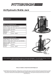
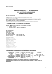
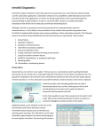
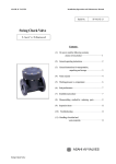
Valve Regulated Lead Crystal Battery
Energy Storage Cells
User Manual
www.bettabatteries.com
[email protected]
1. Introduction
The patented lead crystal battery technology is based on intense research of the defects and operating
characteristics of the lead acid and lead gel batteries. We developed our own trade secret SIO2 composite
electrolyte to replace the traditional sulphuric acid electrolyte commonly used in acid and gel batteries. By using our
own advanced patented battery manufacturing technology and combining it with the new SIO2 composite
electrolyte, we developed a much more superior battery replacement.
By using the innovative new patented composite lead crystal electrolyte technology (our special formula) to
completely replace the traditional sulphuric acid, it brought a great change to the battery product’s internal and
chemical structure.
During initial charging cycles, the liquid composite electrolyte reacts with the lead plates which cause the electrolyte
to crystallize. The crystallized electrolyte fixes to the active material on the plates, enhancing the channel for ion
exchange, effectively overcoming loss of moisture, plate sulphation and loss of active material. A superior resistance
to low temperatures, over charging and over discharging are results of the new chemical structure inside the lead
crystal batteries. This effectively multiplies the product’s service and cycle life.
The CNFJ range is specially designed for alternative energy storage. It accepts a wide range of charging currents and
does not rely on high currents to start and maintain the chemical reaction, making it the perfect storage battery for
solar and wind generators that deliver intermitted charging at variable and interrupted currents.
2. Product Features
The birth of the lead crystal battery is a revolutionary technological breakthrough in the battery industry. It solves
most defects of lead acid and gel batteries such as serious environmental pollution, low fast charging ability, plate
sulphuric acid sulphation, short cycle life and low temperature performance ability are amongst a few. A lead crystal
battery combines all the advantages of long cycle life, high efficiency, low and high temperature resistance, low
internal resistance and environmental safety to make it a much more superior product.
2.1. Structure characteristic
2.1.1. Special Electrolyte Composition
By using a unique blending technology, we are able to combine a variety of inorganic salts and
organic substances to co-ordinate a combined reaction to improve the reaction ability between the
electrolyte and active material on the lead plates. The electrolyte prevents the active material from
becoming brittle and falling of the plates, improving the cycle life.
After several charge and discharge cycles the liquid electrolyte transforms into a crystallized state
leaving no free liquid electrolyte in the battery. This opens a wide range of installation applications,
since the risk of electrolyte leakage is eliminated. This reaction also improves the products safety
making it less harmful to installers and users alike.
2.1.2. Special Manufacturing Process
Using pressure filling technology in combination with patented gravity filling containers to fill the
batteries with electrolyte and the patented terminal connecting equipment, these improvements
ensure a much more even distribution of electrolyte in each cell further enhancing the performance
of the batteries and increasing the efficiency.
2
www.bettabatteries.com
[email protected]
2.2. Performance Characteristics
2.2.1. Long service life
Twice as long as regular lead acid and gel batteries
2.2.2. Deep discharge ability
Can be discharged to 0 volt and be recovered under normal charging conditions to 100% capacity
within 2 cycles.
2.2.3. Extreme environmental temperature resistance
Can be cycled in -40°C to +65°C conditions and used as normal. It performs especially well in the
low temperature ranges.
2.2.4. Environmentally friendlier
Classified as non-dangerous, non-explosive and non-radioactive goods by various governmental
institutions.
3. Working Principle
The main electrochemical reaction during the charge and discharge process of the lead crystal battery:
PbO₂ + 2H₂SO₄ + Pb
Discharge
←
→
Charge
Lead dioxide + Diluted sulphuric acid + Lead
Positive Plate
Composite
Negative Plate
Active Material Electrolyte Active Material
PbSO₄ + H₂O + PbSO₄
Lead sulphate + Water + Lead sulphate
Positive
Water
Negative
Discharge material
Discharge material
When discharging, the positive and negative active material reacts with the acidic element of the electrolyte and
becomes lead sulphate and water, causing the acid density to decrease. When charging, the acid that
concentrated in the positive discharge material (during discharge cycle) is released back into the electrolyte. At
this time the lead sulphate in the positive and negative plate transforms in to lead dioxide and a spongy type of
lead which causes the acid density in the electrolyte to increase.
With normal lead acid batteries, after charging or prior to charge completion, all the charging current is used for
electrolyses of the moisture in the electrolyte. The positive plates release oxygen and the negative plate
hydrogen gas. If the gas recombination efficiency of the battery is low, a large percentage of the gas will escape
leaving less moisture in the battery after every charge. This action causes the electrolyte content to decrease
due to water loss, raising the acidity in the battery and shortening the life of the battery. This is known as late
charge fluid loss phenomenon.
Lead crustal batteries, besides the regular chemical reaction, the composite electrolyte has various additives that
participate in the electrochemical reaction. The additives inhabit the oxygen and hydrogen gas during the
charging cycle increasing the batteries recombination rate. This in turn reduces the water loss during and after
charging. When discharging, the lead sulphate can be totally transformed back into active material, prolonging
the battery’s use life.
The lead crystal group of batteries uses a new advanced type of AGM material as a separator. The AGM has
much higher electrical conductivity, heat resistant and acid resistant abilities than standard AGM on the market.
The crystallized electrolyte in combination with the AGM can effectively protect the
3
www.bettabatteries.com
[email protected]
plates and prevent the active material from falling off during use. The electrolyte is completely absorbed and
stored in the AGM. Since the AGM is completely saturated with electrolyte then crystallized, no free liquid
electrolyte will be present in the battery. The battery can now be used in various directional positions without
leaking.
4. Specifications
4.1. Product specification and model identification method
6
- CN FJ - 120
Rated capacity in Ah (Amp hours)
Valve controlled, sealed lead crystal storage cell
Energy storage battery
Number of cells 6 = 12 volt, 3 = 6 volt
4.2. Model specification table
10hr Discharge rate
Model
Number
Rated
Voltage
V
I10/A
3-CNFJ-10
6-CNFJ-10
6-CNFJ-22
6-CNFJ-24
6-CNFJ-28
6-CNFJ-40
6-CNFJ-55
6-CNFJ-65
6-CNFJ-90
6-CNFJ-100
6-CNFJ-120
6-CNFJ-150
6-CNFJ-180
6-CNFJ-200
CNFJ-300
CNFJ-500
CNFJ-800
CNFJ-1000
CNFJ-2000
CNFJ-3000
6
12
12
12
12
12
12
12
12
12
12
12
12
12
2
2
2
2
2
2
1
1
2.2
2.4
2.8
4
5.5
6.5
9
10
12
15
18
20
30
50
80
100
200
300
Rated
Capacity
Ah
10
10
22
24
28
40
55
65
90
100
120
150
180
200
300
500
800
1000
2000
3000
Outer dimension
±2mm
120hr Discharge Rate
End
Voltage
V
5.4
10.8
10.8
10.8
10.8
10.8
10.8
10.8
10.8
10.8
10.8
10.8
10.8
10.8
1.8
1.8
1.8
1.8
1.8
1.8
I120/A
0.12
0.12
0.22
0.24
0.28
0.48
0.55
0.65
0.9
1
1.2
1.5
1.8
2
3
5
8
10
20
30
Rated
Capacity
Ah
14.4
14.4
26
28
34
48
66
78
108
120
144
180
216
240
360
600
960
1200
2400
3600
End
Voltage
V
5.55
11.1
11.1
11.1
11.1
11.1
11.1
11.1
11.1
11.1
11.1
11.1
11.1
11.1
1.85
1.85
1.85
1.85
1.85
1.85
L
W
H
151
151
181
185
175
198
229
348
306
408
408
486
522
522
176
244
410
475
491
712
50
99
76
105
166
166
138
167
169
174
174
170
240
240
154
175
175
175
351
353
102
105
172
135
125
172
220
175
240
235
235
241
244
244
365
365
366
365
383
382
Weight
kg
2.0
4.2
6.9
7.7
9.0
14.2
18.4
22.0
28.0
33.0
37.0
45.0
60.0
62.0
22.0
32.5
55.5
65
130
192
5. Product standards
Lead crystal battery products are manufactured to meet the following national and international standards and
are manufactured under the ISO 9001 system.
GB/T22473-2008 lead-acid energy storage battery
GB/T19638.2-2005 fixed type valve-controlled sealed battery
Q/TDZG05-2010 fixed type valve control sealed lead crystal battery
BS 6290 part 4 , Telcordia SR 4228, Eurobatt guide, UL, IEC-60896-21/22
4
www.bettabatteries.com
[email protected]
Chapter 2: Technical characteristics
1. Discharge characteristics
1.1. Battery capacity definition
Batteries under certain discharge conditions will release a certain amount of current. This amount od
current released is called the capacity. The symbol used to identify the capacity is “C”. The commonly used
unit of measure is Amp Hours (Ah).
1.1.1. The battery capacity
The battery capacity can be defined in two parts, namely rated capacity and actual capacity under
different discharge conditions. The actual capacity of the battery under certain discharge conditions
is calculated by the current (A) multiplied by the discharge time (h). The resulting unit is Ah.
1.2. Influencing factors on the battery capacity
1.2.1. Discharge rate to influence the capacity
The battery discharge rate uses rated hours to determine the discharge time. This time is influenced
by the amount of current drawn from the battery. If the discharge current increases, the discharge
time will decrease and also affect the rated capacity.
Hour rated discharge:
Rate of discharge:
C10 = 10 hour rated capacity (Ah)
C120 = 120hour rated capacity (Ah)
1C = 1 multiplied by the 10 hour rated capacity used for the discharge
current (A)
0.01C = 0.01 multiplied by the 10 hour rated capacity used for the
discharge current (A)
The curve graph below indicates different constant discharge currents over time of discharge at a
temperature of 25°C and its effect on terminal voltage.
5
www.bettabatteries.com
[email protected]
1.2.2. The influence of temperature on the capacity
In Figure 1 you will notice the effect of temperature on the capacity of the CNFJ series lead crystal
batteries. To calculate the capacity of the battery when the environmental temperature is not 25°C,
the below formula is used:
Ct = the actual capacity at a certain temperature
t = the environmental temperature at the time of discharge (°C)
Capacity(%)
K = the temperature coefficient (10 hour rate coefficient is 0.006)
120
100
80
60
40
20
0
-40 -30 -20 -10
0
10
20
30
40
50
60
Temperature(℃)
Figure 1: CNFJ series lead crystal cell relationship between discharge capacity and temperature.
1.2.3. Discharge termination voltage
The termination voltage refers to the battery voltage dropping during discharge and falls to the
minimum working voltage required for operation. The termination voltage and the discharge current
are closely related. Generally during high current discharge the termination voltage of the battery
should be set lower.
During long term operation at small discharge currents, the battery will form a thin layer of
sulphation on the plates, increasing their size. This could cause deformation af the active material
and cause it to fall off the plates. To prevent this and also to protect the battery during small current
operations, the termination voltage should be set higher.
Over discharging below the termination voltage should be avoided since the over discharging could
only gain a small amount of additional capacity, but drastically reduce the battery’s service life.
6
www.bettabatteries.com
[email protected]
The below table indicates recommended termination voltages at different rates of discharge for the CNFJ range.
Discharge termination
Discharge current(A)
voltage (V/Cell)
Below 0.05C or non constant
1.9
discharge
Equal/close to 0.05C
1.85
Equal/close to 0.1C
1.8
Equal/close to 0.2C
1.75
0.2C ~ 0.5C
1.7
0.5C ~ 1C
1.6
1C ~ 3C
1.5
Above 3C
1.3
1.2.4. Self-discharging of the lead crystal batteries
Lead crystal batteries with the use of our unique crystal composite electrolyte and alloy grid plate
technology, efficiently reduces the battery self-discharge consumption. At a constant 25°C
environment, the batteries can be kept on a shelf for more than one year without constant top up
charging and the battery will maintain over 85% of its rated capacity.
The self-discharge characteristics of the battery change with environmental temperatures. The
higher the temperature the higher the self-discharge, so the batteries should not be stored in an
environment that is subjected to high temperature conditions for long durations of time.
Storage Capacity (25°C)
7
3 months
95%
6 months
90%
1 year
85%
www.bettabatteries.com
[email protected]
2. Charging characteristics
2.1. Charging conditions are the key factors that affect battery life and functionality
The CNFJ range of lead crystal batteries should be charged using constant voltage for both floating and
cyclic charge applications.
2.2. The relationship between charge voltage and environmental temperature
The battery benchmark temperature setting should be assumed to be 25°C. Under different environmental
temperature conditions a temperature compensation coefficient of -3mV/°C/Cell should be applied to the
charging equipment. This equipment’s voltage stability factor should be ±1% or higher.
2.3. Equipment setting
During the initial charge and discharge cycles the depth of discharge, discharge current, operating
temperature and time of discharge should be recorded. Equipment must then be recalibrated to the
recorded parameters as to ensure longer life of both the batteries and the equipment. After complete
discharge, the battery should periodically be fully charged and discharged for at least two complete cycles
to ensure full recovery of the battery’s capacity. The abovementioned results should be recorded and again
adjustment should be made to the equipment if necessary.
2.4. Float charging applications
For applications that is constantly connected to the electrical grid and where the batteries are in constant
charging state and only discharged when there is a break in or loss of grid supply, the charging equipment
should be set to the float charging mode. The equipment should be set and monitored so that strict control
can be maintained over charging to ensure a constant charging voltage and current.
Recommended floating charge voltage should be between 2.25 – 2.3V/Cell and the floating current should
be between 0.005 – 0.01A. In long term float charging applications, a six month balanced charge and
discharge should be performed as part of battery maintenance, where the balanced cycles should be no
more than 8 – 12 hours in duration. During the initial charge and discharge cycles on new installations the
charge current should be limited to 0.1C – 0.25CA (not to exceed 0.3CA) and the temperature not more
than 35°C. During this stage of operation if an increase of temperature is noticed the charge current should
be reduced.
2.5. Charging characteristic curve
The below curve graph shows typical charge characteristics of the lead crystal batteries.
8
www.bettabatteries.com
[email protected]
Chapter 3:
Battery Installation
1. Installation method an sequence
1.1. After the batteries are unpacked, check for any visible damage to the product.
1.2. Please read this manual before installation to ensure correct installation according to required application
and equipment settings.
1.3. Ensure that the batteries remain in the shipping packaging until it arrives on the installation site. When the
batteries are handled please take care not to lift the batteries by means or the terminals to avoid damage
to the internal seals. Always lift the batteries by the supplied handles or from the bottom of the batteries in
the event that the battery is not designed or supplied with the required lifting handles.
1.4. Before connecting the equipment to the batteries, use a piece of fine grit sandpaper to sand the contact
area of the terminal and the connecting lug. This will ensure good contact between battery and lug and
reduce the risk of oxidation.
1.5. When there are multiple batteries connected together in a group (series or parallel), ensure that the voltage
of the batteries in the group match prior to connecting. Ensure the connections on the batteries are secure
and the configuration is according to the voltage required to operate the equipment. Before connecting the
load, charge the batteries to a state of full charge to ensure all the batteries are on the same level. At this
point it is safe to connect the batteries.
2.
Matters that need attention during installation
2.1. Ensure that all heating and cooling ducts are directed away from the batteries. The installation site should
be kept clean, dry and well ventilated at all times. Avoid installing the batteries in direct sunlight, away from
a heat source, organic solvents and corrosive gas to ensure longer battery life and to prevent accidents.
2.2. All the lead crystal batteries are fully charged prior to shipping to activate the crystallization of the
electrolyte in the batteries. Care should be taken when handling the batteries during transport and prior or
during installation to prevent short circuit and reverse connection in order to avoid damage to the
equipment and harm to people.
2.3. Because of high voltage and the risk of electrical shock, the batteries should be handled with great care
during transportation and when being installed. Electrically insulated equipment and clothing should be
used/worn when working with or connecting batteries.
2.4. Smudgy, oily and loosely connected connections could cause contact problems and lead to faults on the
equipment. Ensure that all contacts are clean from oil and grease and that all connections are securely
fastened. Terminals should be torque to individual battery specifications, but not exceed 15N.m. Excessive
tightening will cause damage to the thread on or inside the battery terminal. Terminal connections should
be checked periodically during the life of the battery to ensure that there are no loose connections.
2.5. Ensure that the batteries are connected in the correct way. Ensure that reverse polarity are eliminated by
connecting positive to positive and negative to negative on the equipment. Also ensure that the correct size
of wire diameter is used according to current drawn requirement. If incorrect wires are used, it will heat
rapidly and cause damage to both the battery and the equipment that it is connected to.
3.
Correct use and maintenance
3.1. The batteries are designed for a usage environment to operate in extreme environmental temperatures
ranging from -40°C - +65°C. Yet, most installations and best recommended environmental temperatures for
use are -5°C - +35°C and a relative humidity of 95%. The CNFJ range of batteries can be used in both float
and cyclic charge applications at different environmental conditions.
9
www.bettabatteries.com
[email protected]
4. Charge and discharge regulations
4.1. The CNFJ range of batteries should be charged according to the specified voltages and currents indicated in
chapter 2.
4.2. The CNFJ range of batteries should be discharged according to the termination voltage specified in chapter
2 and in accordance with the equipment requirements. This will ensure long life of both the battery and the
equipment.
5. Battery maintenance
5.1. Perform an inspection of the batteries prior to installation.
5.1.1. Check for damage to ABS plastic shell
5.1.2.Check batteries open circuit voltage and calculate the per cell voltage if the voltage is less than
2.1V/Cell. The batteries should be charged individually to correct the balance.
5.1.3.Make a battery maintenance and operation file and record all relevant information during the life of
the battery.
5.2. Operating maintenance
5.2.1.Monthly inspection and maintenance
Content
Method
Inspection standard
Solution
Adjust
voltage
=
charging and discharging
The total voltage
Equipment should be
Total voltage = charging
when the Battery is
calibrated with an deviation of
and discharging voltage
charging and
no more than 0.5 volt before
x quantity of batteries in
discharging
testing batteries in a group
the group
voltage
× quantity of
batteries in the group,
replace
defective
battery/ies if individual
charging does not bring
the
voltage
back
required level
Use the voltmeter to
Controller
measurement the controllers
Check if the results meet
Charge and
output voltage, highest charge
the required
discharge voltage
voltage and over discharge
specifications
Adjust the controller
voltage parameters
protection voltage
Use the ammeter to
Controller
Charge and
discharge current
measurement the controllers
output current, highest
charge current and over
Check if the results
meet the required
specifications
discharge protection
10
www.bettabatteries.com
[email protected]
Adjust the controller
current parameters
to
5.2.2.Six monthly maintenance and inspection
Content
Method
Inspection standard
Solution
Adjust voltage =
charging and
The total voltage
Equipment should be
Total voltage = charging
when the Battery is
calibrated with an deviation of
and discharging voltage
charging and
no more than 0.5 volt before
x quantity of batteries in
discharging
testing batteries in a group
the group
discharging voltage ×
quantity of batteries in
the group, replace
defective battery/ies if
individual charging does
not bring the voltage
back to required level
Use the voltmeter to
Controller
measurement the controllers
Check if the results meet
Charge and
output voltage, highest charge
the required
discharge voltage
voltage and over discharge
specifications
Adjust the controller
voltage parameters
protection voltage
Use the ammeter to
Controller
Charge and
discharge current
measurement the controllers
output current, highest
charge current and over
Check if the results
meet the required
specifications
Adjust the controller
current parameters
discharge protection
Check if there are visible
-
leaking of electrolyte
Visual inspection of
the batteries
If there is: the battery
should be replaced
Check if the battery is free
If there is pollutant or
-
from dust and pollutants
dust clean with a moist
cloth
appearance
Check if there is water
Find the source of water
present in the battery
container/enclosure and if the
-
terminals and cables are
dusty or corroded
11
www.bettabatteries.com
[email protected]
and repair clean or
repair corroded cables if
possible replace.
5.2.3. Annual maintenance and inspection
Annual inspection should include six monthly maintenance check and also perform the following
procedures and inspections:
Content
Terminal
connections
and cables
Method
Inspection
standard
Solution
Ensure good
See installation
According to
connection of the
requirements
the battery
nuts and bolts on the
and tighten to
specification
battery terminals and
individual
tighten and
connections on
battery
torque nuts and
equipment
specification
bolts
5.3. Maintenance while inspecting the battery
5.3.1.Check for damage, leakage and deformation.
5.3.2.Check if there are any loose connections and tighten according to specification.
5.3.3.Check if the voltage over the group is balanced.
6. Remarks
6.1. Battery maintenance should be performed by professionals.
6.2. Avoid constant over discharging of the batteries.
6.3. When batteries are discharged, the termination voltage should be set according to the discharging current
requirement. The over discharge protection should be set to be ±0.05V lower than the termination voltage
to ensure good operation and long life of the batteries and equipment. After the battery is discharged, it
should be immediately be charged again.
6.4. When abnormalities or damage is noticed, the problem should be investigated immediately. If the battery
was the cause it should be replaced immediately to prevent further damage.
6.5. When charging the battery the controllers charge voltage accuracy should be less than ±1% to prolong
battery service life.
6.6. All display instrumentation should be regularly checked and calibrated to ensure accurate reading of
measurements. If the equipment can’t read an error the equipment could cause damage to the batteries.
Chapter 4:
Transportation and storage
1. During transportation please perform safe handling of batteries. Due to the weight of the batteries it should be
handled with care in order to not drop the batteries while loading and offloading.
2. Use appropriate lifting techniques while handling batteries. Never lift the batteries by means of the terminals or
ventilation valves.
3. Note that the batteries are charged and could cause electrical shock to personnel and damage to the battery and
equipment if the terminals are short circuited.
4. The batteries should be stored in a clean, dry and well ventilated place where the ambient temperature is
between 5°C - 30°C. Batteries should be rotated to ensure on shelf storage is approximately 6 months. Longer
storage of up to 24 months is possible and would not cause damage to the batteries, but it would need to be
charged prior to installation.
12
www.bettabatteries.com
[email protected]
5. Avoid contact with organic solvents and corrosive liquids. Also prevent metal impurities from falling in to the
battery.
6. Keep batteries free from mechanical shock and heavy pressures.
7. Half used batteries can be stored for future use. It should be charged prior to storage then stored according to
safe storage practise.
Appendix:
When selecting the appropriate battery for a project the following parameters should be considered and the below
formula used to calculate the quantity and size of battery needed. System output and maximum power, continuous
rainy day storage, quantity of solar panels wind generators or both and the total system current.
To determine the battery capacity, use the following formula:
C-K1 x W/V x T x (d + 1)/0.8
C = Battery capacity in Ah.
K1 = safety coefficient normally set as 1.2
W = system output power in watt (W)
V = system operating voltage in volt (V)
T = daily operating time in hours (h)
d = continuous rainy days
13
www.bettabatteries.com
[email protected]