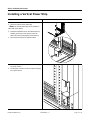
1
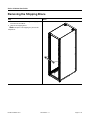
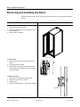
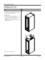
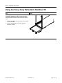
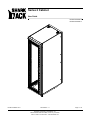
Series 2 Cabinet
User Guide
ECAB-R19-SRS2-70
ECAB-R19-SRS2-77
ECAB-R19-SRS2-70/77
05/15/03 Rev 1.1
Proprietary Information of SharkRack, Inc.
32920 Alvarado Niles Road #250, Union City, CA 94587
510-477-7900• 510-324-1664 • www.sharkrack.com
Page 1 of 13
Series 2 Cabinet User Guide
Table of Contents
Removing the Shipping Brace. . . . . . . . . . . . . . . . . . . . . . . . . . .3
Removing and Installing the Doors . . . . . . . . . . . . . . . . . . .. . . . .4
Adjusting the Middle Rails. . . . . . . . . . . . . . . . . . . . . . . . . . . . . .5
Installing a Fan Top. . . . . . . . . . . . . . . . . . . . . . . . . . . . . . . . . . . 6
Removing and Installing the side Panels . . . . . . . . . . . . . . . . . . ..7
Installing the MultiBay Kit . . . . . . . . . . . . . . . . . . . . . . .. . . . . . . 8
Using the Heavy Duty Retractable stabilizer Kit . . . . . . . . . . . .10
Installing a Vertical Power Stri . . . . . . . . . . . . . . . . . . . . . . . . .11
Installing a 19” EIA Power Strip . . . . . . . . . . . . . . . . . . . . . . . . 12
ECAB-R19-SRS2-70/77
05/15/03 Rev 1.1
Page 2 of 13
Series 2 Cabinet User Guide
Removing the Shipping Brace
Step
Detail
1. Remove the four screws securing the shipping brace
to the front of the cabinet.
2. Remove the shipping brace.
Note: This piece is for shipping only and can be
disposed of.
ECAB-R19-SRS2-70/77
05/15/03 Rev 1.1
Page 3 of 13
Series 2 Cabinet User Guide
Removing and Installing the Doors
Both front and rear doors can be easily removed for better access to equipment inside the
cabinet.
Step
Detail
To remove doors:
1. Open door to expose hinge pins.
2. Remove hinge pins from door by pulling up on the
pin. (See Figure A).
3. Remove door from cabinet.
To install doors:
1. Align the hinge on the door with the hinge on the
cabinet.
2. Insert hinge pins into hinges.
3. Close door and verify that the locking mechanism
works properly. Some adjustment to the door latch
may be necessary.
Figure A
To adjust door latch:
1. Loosen screws holding latch. (See Figure B)
2. Adjust latch up or down as required.
3. Tighten screws.
4. Test latch. (Repeat steps 1-4 until properly adjusted)
Figure B
ECAB-R19-SRS2-70/77
05/15/03 Rev 1.1
Page 4 of 13
Series 2 Cabinet User Guide
Adjusting the Middle Rails
The middle mounting rail is adjustable to accomodate a variety of computer mounting
depths.
Step
Detail
1. Loosen the 1/4-20 cap screws at the top and the
bottom of the left middle rail.
2. Once the screws have been loosened you can adjust
the left rear rail to the desired location. Make sure the
rails are adjusted parallel and square inside the
cabinet.
3. Tighten the 1/4-20 cap screws at both the top and
bottom of the left middle rail.
4. Repeat steps 1 through 3 for the right middle rail.
ECAB-R19-SRS2-70/77
05/15/03 Rev 1.1
Page 5 of 13
Series 2 Cabinet User Guide
Installing a Fan Top
Step
Detail
To remove top panel:
1. Remove four screws from the top of the cabinet.
2. Lift the top panel from the cabinet.
To install fan top:
1. Set the fan top on the top of the cabinet.
2. Secure the fan top to the cabinet using four screws.
3. Plug the power cord into a power source.
Note: The fan top occupies the first RU space at
the top of the cabinet.
*Cabinet shown with optional front door
ECAB-R19-SRS2-70/77
05/15/03 Rev 1.1
Page 6 of 13
Series 2 Cabinet User Guide
Removing and Installing the Side Panels
The side panels can be removed to provide further access to equipment mounted inside
the cabinet or to install MultiBay Kits.
Step
Detail
To remove panels:
1. Loosen eight screws from the side panel, working
from the bottom up.These are captive screws and will
not pull out of their holes.
2. Remove the panel.
3. Repeat steps 1 and 2 for the other side panel.
To install panels:
1. Set the side panel in place.
2. Screw in captive screws but do not fully tighten. After
the side panel is adjusted to its desired fit, tighten all
the screws.
3. Repeat steps 1 and 2 for the other side panel.
*Cabinet shown with optional front door
ECAB-R19-SRS2-70/77
05/15/03 Rev 1.1
Page 7 of 13
Series 2 Cabinet User Guide
Installing the MultiBay Kit
The MultiBay kits are used to group two or more cabinets together.
Step
Detail
1. The front and rear peices of the Multibay kit come
pre-assembled. Remove the screws holding these
pieces together. This will give you (5) individual
pieces.
Top Trim Piece
2. The side panels need to removed from in between
the cabinets that are attached. See “Removing Side
Panels” on page 7.
MultiBay Flange
3. Attach the multibay flange to the cabinet using the
same fastening locations as the side panels. Fasten
the flange using (4) 1/4-20 cap screws.
4. Repeat step 3 for the front and rear of each cabinet
being attached.
ECAB-R19-SRS2-70/77
05/15/03 Rev 1.1
Page 8 of 13
Series 2 Cabinet User Guide
Step
Detail
5. Once the two mounting flanges have been secured to
the cabinet, attach the top trim piece to the cabinet.
Attach the trim piece to the studs on the mounting
flanges. Secure the top piece to the flanges using (2)
10-32 nuts.
Note: The top trim piece can be omitted in order to
run cables through the center of the cabinets.
6. Once the two cabinets have been prepared, slide
them together. Making sure that the oblong holes sit
in front of the threaded holes. Secure the two
cabinets using (3) screws in front and (3) screws in
the rear.
ECAB-R19-SRS2-70/77
05/15/03 Rev 1.1
Page 9 of 13
Series 2 Cabinet User Guide
Using the Heavy Duty Retractable Stabilizer Kit
Step
Detail
The heavy duty retractable stabilizer kit should be used
when sliding equipment in and out of the rack cabinet
and the rack cabinet is not secured to the floor. This
feature is used to prevent the rack cabinet from tipping
over.
1. Pull out the stabilizer bar at the bottom of the cabinet
until fully extended.
2. Unscrew the stabilizer feet until they are firmly
planted on the floor.
ECAB-R19-SRS2-70/77
05/15/03 Rev 1.1
Page 10 of 13
Series 2 Cabinet User Guide
Installing a Vertical Power Strip
Step
Detail
1. Open the rear door of the cabinet.
2. Choose a location for the power strip.
Note: The vertical power strip can be installed on
either side of the cabinet.
3. Install the trapezoidal nut into the cabinet frame by
installing the thin part of the spring nut into the
cabinet and turning it 90 degrees.( See Figure A)
4. Place the power strip in the desired location.
5. Secure the power strip to the cabinet frame using (2)
1/4-20 cap screws.
6. Pull the power cord from under the cabinet and plug
into a power source.
ECAB-R19-SRS2-70/77
05/15/03 Rev 1.1
Page 11 of 13
Series 2 Cabinet User Guide
Installing a 19” EIA Power Strip
Step
Detail
1. Open the rear door of the cabinet.
2. Choose a location for the horizontal power strip.
Note: Ensure that there is enough clearance
between the rear door and the power strip to attach
power cords.
3. Secure the power strip to the rack rails by using four
10-32 x 1/2-inch pan head screws.
4. Pull the power cord from under the cabinet and plug
into a power supply.
ECAB-R19-SRS2-70/77
05/15/03 Rev 1.1
Page 12 of 13
Series 2 Cabinet User Guide
Warranty
LIMITED WARRANTY AND WARRANTY DISCLAIMER - Seller warrants that the System will be
free from defects in materials and workmanship for a period of one (1) year from date of delivery
to customer premises. Seller’s sole liability and Customer’s sole and exclusive remedy for any
breach of this warranty is, at Seller’s option and expense, to repair or replace any defective
System that is returned to it by Customer. Seller will have no obligation under this section to the
extent any defect in the System is caused by or is attributable to negligence, accident, misuse,
abuse, use of the System than in accordance with Seller’s documentation or user manual,
modifications, alterations or repairs to the System made by a party other than Seller, or actions of
third parties or like events outside Seller’s reasonable control. EXCEPT AS EXPRESSLY SET
FORTH IN THIS SECTION, TO THE EXTENT PERMITTED BY APPLICABLE LAW, SELLER
DISCLAIMS ANY AND ALL OTHER WARRANTIES, WHETHER EXPRESS, IMPLIED, OR
STATUTORY, INCLUDING, WITHOUT LIMITATION, ANY IMPLIED WARRANTIES OF
MERCHANTABILITY, FITNESS FOR A PARTICULAR PURPOSE, QUALITY, OR
NONINFRINGEMENT, AND ANY WARRANTIES ARISING FROM COURSE OF DEALING OR
USAGE OF TRADE.
LIMITATIONS OF LIABILITY - IN NO EVENT WILL SELLER BE LIABLE FOR ANY SPECIAL,
INCIDENTAL OR CONSEQUENTIAL DAMAGES (INCLUDING, BUT NOT LIMITED TO, LOST
PROFITS OR REVENUE, LOSS OF USE, LOST BUSINESS OPPORTUNITIES OR LOSS OF
GOODWILL), OR FOR THE COSTS OF PROCURING SUBSTITUTE PRODUCTS, ARISING
OUT OF OR IN CONNECTION WITH THESE TERMS OF SALE OR THE USE OF THE
SYSTEM, WHETHER SUCH LIABILITY ARISES FROM ANY CLAIM BASED UPON
CONTRACT, WARRANTY, TORT (INCLUDING NEGLIGENCE), PRODUCT LIABILITY OR
OTHERWISE, WHETHER OR NOT SELLER HAS BEEN ADVISED OF THE POSSIBILITY OF
SUCH LOSS OR DAMAGE. IN NO EVENT WILL SELLER’S TOTAL CUMULATIVE LIABILITY,
FROM ALL CAUSES OF ACTION AND ALL THEORIES OF LIABILITY, EXCEED THE TOTAL
AMOUNTS ACTUALLY PAID TO SELLER BY CUSTOMER UNDER THE ORDER THAT GIVES
RISE TO ANY LIABILITY HEREUNDER.
ECAB-R19-SRS2-70/77
05/15/03 Rev 1.1
Page 13 of 13