1
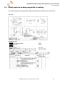
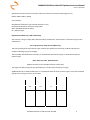
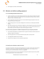
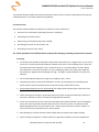
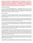
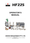
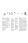
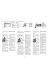
PMBWELD301B Butt Weld PE Pipelines Resource Manual POLYSMART Pty Ltd ACN 141 203 956 Ph: 1300 DO POLY 1300 36 7659 International: +613 8770 5711 www.polysmart.com.au [email protected] PMBWELD301B Butt Weld PE Pipelines Resource Manual Revision 3/03/2015 Hello Thank you for purchasing this Polysmart learning package. In this package you will receive all the information as required in the national competency unit for PMBWELD301B Butt Weld polyethylene pipelines. When you have studied all the learning material you will be able to sit the theory assessment. This assessment requires a 75% pass rate; any questions that you get wrong will be discussed with your assessor prior to starting the practical assessment. Minimum computer requirements: Windows XP Operating System, PC Speakers or Headphones, Internet Explorer 6 or Firefox 3 Adobe Flash Plug‐In, Internet Connection. If you have any difficulties or comments regarding this package please do not hesitate to contact our assessor for assistance. Email: [email protected] or phone 1300 36 7659. Table of Contents 1.0 Identify materials as being compatible for welding. ................................................................... 4 2.0 Calculate appropriate pipe welding parameters. ........................................................................ 7 3.0 Maintain and calibrate welding equipment. ............................................................................. 12 4.0 Perform welding. ....................................................................................................................... 16 5.0 Assess Quality of Completed Joints. .......................................................................................... 19 Appendix A ............................................................................................................................................. 21 Glossary of Terms .................................................................................................................................. 23 ©2010 Polysmart Pty Ltd ACN 141 203 956 2 PMBWELD301B Butt Weld PE Pipelines Resource Manual Revision 3/03/2015 This competency in practice. This competency applies to operators who are involved in the electrofusion of polyethylene (PE) pipes and pipeline components to quality assurance requirements, whilst maintaining personal and immediate site safety. The key features in attaining the required quality are; 1. 2. 3. 4. 5. Identifying materials being used in the installation as compatible for welding. Calculating appropriate welding parameters to be used. Maintaining and calibrating welding equipment. Performing welding. Assessing quality of welded joints made. End applications include pipelines for transmitting gas and liquids. The following document has been prepared as reference material for the unit “PMBWELD301B” ©2010 Polysmart Pty Ltd ACN 141 203 956 3 PMBWELD301B Butt Weld PE Pipelines Resource Manual Revision 3/03/2015 1.0 Identify materials as being compatible for welding. 1.1 Identify materials as polyethylene (PE) from specifications and work site Instructions. Fig: 1 Plan Fig: 2 Works order ©2010 Polysmart Pty Ltd ACN 141 203 956 4 PMBWELD301B Butt Weld PE Pipelines Resource Manual Revision 3/03/2015 Specifications and work site instructions will have reference to PE Pipe and fittings such as: DN225, PN16, SDR11, PE100 This indicates: DN (Diameter Nominal)= Pipe outside diameter in mm, PN (Pressure Nominal)= Pressure rating in Bar, SDR = Standard Dimension Ratio, PE = Material type Explanation of Material / SDR relationship The pressure rating of a pipe (PN) is determined by the diameter, wall thickness, and material type and is expressed as: PN ‐ Pipe pressure rating at 20°C (MPa x 10) The basic polyethylene (PE) material types used for pipe production are PE 63, PE 80 and PE 100, the number indicating long term strength. The term SDR, Standard Dimension Ratio, is introduced to describe the pipe, in combination with the material type. SDR = Min. OD ÷ Min. Wall Thickness (Where OD refers to the Outside Diameter of the pipe) The higher the SDR, the thinner the wall thickness, and the lower the pressure rating. AS/NZS 4130 uses a standard SDR series, in combination with the three material types, to provide standard pipe pressure ratings as shown in the table. PE63 PE80 PE100 SDR PN PN PN 3.2 4 41 33 3.2 26 4 21 4 6.3 6.3 8 17 6.3 8 10 13.6 8 10 12.5 11 10 12.5 16 9 12.5 16 20 7.4 16 20 25 ©2010 Polysmart Pty Ltd ACN 141 203 956 5 PMBWELD301B Butt Weld PE Pipelines Resource Manual Revision 3/03/2015 1.2 Identify PE materials and pipes supplied as being compatible for welding from specifications. Inspection of goods received for use. The installer should ensure that incoming pipe, fittings and fusion jointing equipment are not used until they have been inspected and confirmed as conforming to specified requirements, including appearance and marking. Any non‐conforming items should be identified, recorded and segregated. Pipe Markings. Marking details shall be legibly printed or formed directly on the pipe. Manufacturer's name or registered trade mark, and pipe series number, in the form TRADE MARK S1, as appropriate. i. For Series 1 pipes: Nominal diameter, Classification and SDR, in the form 'DN 25 PN 4 SDR 33', as appropriate. ii. For Series 2 pipes: Nominal diameter and SDR, in the form 'DN 160 SDR 11', as appropriate, and the word 'GAS'. iii. For Series 3 pipes: Nominal diameter, Tmin. and SDR, in the form 'DN 40x4.4 SDR 11, as appropriate, and the word 'GAS'. iv. For pipes dimensions in accordance with Appendix D: Nominal diameter and minimum wall thickness, in the form 'DN 250x11.2', as appropriate. v. PE material classification number in the form 'PE 80B', 'PE 100', ETC. as appropriate. vi. Date of manufacture in the form '010515', i.e. the 15th of May, 2001, as appropriate. vii. Identification of the place of manufacture. The manufacturer's code is acceptable, e.g., F1. viii. The number of this Standard, i.e., AS/NZS 4130. Series 1: TRADEMARK S1 DN 25 PN 4 SDR 33 PE 80B 010515 F1 AS/NZS 4130 Series 2: TRADEMARK S2 DN 110 SDR 11 GAS PE 80B 010515 F1 AS/NZS 4130 Series 3: TRADEMARK S3 DN 40x4.4 SDR 11 GAS PE 80B 010515 F1 AS/NZS 4130 Special applications: TRADEMARK SA DN 250x11.2 PE 100 010515 F1 AS/NZS 4130 ©2010 Polysmart Pty Ltd ACN 141 203 956 6 PMBWELD301B Butt Weld PE Pipelines Resource Manual Revision 3/03/2015 2.0 Calculate appropriate pipe welding parameters. Recommended Parameters and Procedures. PIPA (Plastics Industry Pipe Association of Australia Limited) recommends the butt fusion procedures and parameters as specified in ISO 21307, Plastics pipes and Fittings – Butt Fusion Jointing Procedures for Polyethylene (PE) Pipes and Fittings Used in Construction of Gas and Water Distributions Systems. Copies of the ISO standard can be purchased from Standards Australia: www.standards.org.au Parameters Various butt fusion methods have been developed around the world with minor differences adopted in different regions simply on the basis that they were proven to work over a period of time. The International Standards Organisation (ISO) conducted a review of all the methods which resulted in three (3) distinct methods being incorporated into ISO 21307. Single pressure – low fusion jointing pressure (SLP) This method has been used by most European countries and in Australia. The parameters specified are very similar to the previous ones specified in PIPA POP003 issue 5.1. Trained welders competent with these parameters can generally be considered competent to this method. Dual pressure – low fusion jointing pressure (DLP) This method is used by a few authorities in the UK and Europe. It is not widely used but the authorities that use it were adamant that it be adopted by the ISO Standard. These parameters are not commonly used in Australia and it is not expected to be used in Australia in the future. (See Appendix A) Single pressure – high fusion jointing pressure (SHP) This method has been used extensively in Northern America for more than 20 years. The weld pressure is approximately three times the low pressure method and as a consequence more of the hot plastic is extruded from the weld zone, thereby enabling a reduced cooling time. The method is relatively new in Australia and therefore extra attention is required to ensure: I. The welding machines have sufficient structural strength and hydraulic capacity to achieve the high pressure parameters in a safe manner. Confirmation should be sought from the machinery manufacturer. II. The welding operator is sufficiently experienced and proficient with the parameters. This method is expected to become the predominant method for thick‐wall pipes. (See Appendix B) ©2010 Polysmart Pty Ltd ACN 141 203 956 7 PMBWELD301B Butt Weld PE Pipelines Resource Manual Revision 3/03/2015 A successful butt weld requires the correct combination and sequence of the welding parameters time, heat and pressure. It is essential that the parameters specified for a method are followed and to not mix and match parameters from each method. At present, the most commonly used weld parameters are “Single pressure – low fusion jointing pressure” (SLP) parameters. As all welding equipment is compatible with the use of these parameters we will use these in our examples. The Dual pressure – low fusion jointing pressure (DLP) and Single pressure – high fusion jointing pressure (SHP) parameters are attached at the end of this unit for your reference. (Appendix A & B) ©2010 Polysmart Pty Ltd ACN 141 203 956 8 PMBWELD301B Butt Weld PE Pipelines Resource Manual Revision 3/03/2015 Proposed Australian Single Low Pressure fusion jointing procedure (SLP) Butt Fusion Parameter Units Value Heater plate temperature °C 200 - 245 Initial Bead-up pressure kPa P1 Time taken to generate a continuous bead, around the circumference of the ends of the pipes or fittings Initial Bead-up time Visual t1 Initial bead‐up size may vary depending on ambient and other conditions and is not necessarily uniform Initial Bead-up Size Heat soak pressure kPa P2 Drag only second t2 (11 1) en second t3 0.1 en + 4 second t4 0.4 en + 2 kPa P3 170 20 Minimum cooling time in machine under pressure minute t5 en + 3 Minimum cooling time out of the machine prior to rough handling (see note) minute t6 en + 3 Minimum heat soak time Maximum heater plate removal time Max. time to achieve welding pressure Fusion jointing pressure 170 20 ©2010 Polysmart Pty Ltd ACN 141 203 956 9 PMBWELD301B Butt Weld PE Pipelines Resource Manual Revision 3/03/2015 Notes: 1. These parameters apply to the butt fusion of PE80 or PE100 polyethylene materials as specified in AS/NZS 4131. 2. These parameters may also apply to the butt fusion of PE80 to PE100. This may result in slightly different bead formation without reducing weld quality. If in doubt, refer to the pipe maker. 3. Only pipes and fittings of the same diameter and wall thickness should be butt fused together. 4. t = mean pipe wall thickness calculated from AS4130 min/max values, rounded to the nearest mm. 4a. Bead up can be calculated as a measurement or as a time, either of these methods are approved however in our experience the measured example is preferred. 5. D = mean pipe outside diameter calculated from AS4130 min/max values, rounded to the nearest mm. 6. Pressure calculation formula: pipe annulus area (mm²) x pressure value (kPa) hydraulic cylinder area (mm²) Where pipe annulus area = π (D ‐ t)t 7. For ambient temperature > 25°C, cooling time must be increased by 1 minute per °C above 25°C. 8. For ambient temperature < 5°C, cooling time may be decreased by 1 minute per °C below 5°C. 2.1 Identify welding machine type and operating data. ©2010 Polysmart Pty Ltd ACN 141 203 956 10 PMBWELD301B Butt Weld PE Pipelines Resource Manual Revision 3/03/2015 As there are a number of butt welding units available, you must be familiar with the operation of each type that you plan to use. Insist that operation manuals are supplied with the machine that you plan to use. Do not assume that they all are similar as hydraulic ram cross sectional areas will almost certainly differ between sizes and manufactures. Most machines are hydraulically operated, some use a hand operated pump and some have electric hydraulic pumps, and some machines are partially automated (The machines that we will use in this instance are Omisa manual and electro hydraulic machines). 2.2 Identify pipe material and dimensions. Pipes and fittings of different PE materials, which are within the MFR range 0.2 to 1.4 (ISO1133), can also be jointed successfully using butt fusion, provided that all components have adequate nominal pressure rating for the operating conditions and the PE materials comply with AS/NZS 4131. Therefore it is also allowable to weld PE80 pipes and fittings to PE100 pipes and fittings. In more recent times PEX pipes have been manufactured in Australia. These have been produced in diameters around 160mm for artesian water, as this material is more resilient to warm water situations. PEX does not butt weld very well, however, Plasson produce some electrofusion joiners that provide an adequate join. Refer back to section 1.2 for more information. 2.3 Perform welding parameter calculations for individual welding machines and pipe details. Use the attached sheet for; BUTT WELDING PARAMETER CALCULATIONS (SLP) You can also use this sheet to assist in your assessment. For this training exercise we will assume that we will use Vinidex ‐ Series 1, 225mm, SDR11, PE100 pipe and Single pressure – low fusion jointing pressure welding parameters. 2.4 Prepare field operational sheets as per enterprise requirements / procedures. Before calculating weld pressure you need to calculate drag pressure, Static drag pressure is simply how much pressure you need to apply, to move the pipe towards the centre of the machine. Initial movement is referred to as static drag. However you need to record Dynamic drag. This is the pressure that it takes to keep the pipe moving toward the centre of the machine (generally lower than initial drag). The Dynamic drag pressure must be checked and recorded before each weld. ©2010 Polysmart Pty Ltd ACN 141 203 956 11 PMBWELD301B Butt Weld PE Pipelines Resource Manual Revision 3/03/2015 Fill in drag data, and other relevant details. 3.0 Maintain and calibrate welding equipment. 3.1 Set up welding equipment and work area. A shelter should be used to provide adequate protection for pipe, fittings and equipment against adverse weather conditions and contamination of the jointing surfaces by dust and/or moisture, which can result in unsatisfactory joints. Cover the pipe ends remote from the joint, to ensure airflow through the pipeline cannot occur during the heating and cooling cycles. Uneven heating by the sun may affect welding if this is excessive try to shade pipe ends before welding Pipe stands should be used as this helps with alignment, reduces drag and overall makes the process easier. Stands should be placed 1 meter from machine then at 2 meter intervals possibly over a 6 meter distance. The more stands you use the easier the pipe is to handle. 3.2 Ensure safety equipment is available and operational as per enterprise procedures. Treat all electrical equipment as a potential source of ignition and maintain codes of practice for working in explosive atmospheres. Ensure that generators are correctly maintained and that fuel is correctly stored. Fire extinguisher should be easily accessible. Check with site manager as to any site specific requirements. 3.3 Identify non‐conformance, report and rectify. The operator should ensure that fusion jointing equipment is not used until it has been inspected and confirmed as conforming to specified requirements including appearance and marking. Any non‐ conforming items should be identified, recorded and segregated. At the commencement of each contract, the frequency and type of inspection by the service provider should be agreed with the client and documented. ©2010 Polysmart Pty Ltd ACN 141 203 956 12 PMBWELD301B Butt Weld PE Pipelines Resource Manual Revision 3/03/2015 The installer should establish and maintain electronic and/or written records of appropriate servicing and calibration details in accordance with these guidelines. Corrective action. The installer should establish and maintain procedures to show evidence of: Review of non‐conformities (including customer complaints), Evaluating the need for action, Determining and implementing action needed, Recording the results of action taken, and Reviewing corrective action taken. 3.4 Check operation and calibrate where required the heating, trimming, and pressure systems. 1. Heating. The heater plate should be checked for temperature fluctuations on a regular basis. This is easy to check with a surface probe and should be checked at the start of each welding session, after the thermostat has been allowed to cycle a couple of times. It is recommended to check it before each weld then record this information on your welding log. Never rely solely upon fitted dial thermometers, digital thermostat displays or high ‐ low lights. These should be only used as an indicator. The recommended temperature range for PE welding is 200 ‐ 245°C. Temperature probes can be easily checked for accuracy by inserting them into boiling water which will be at 100°C (we find that this method of testing is about 95% correct). Infrared thermometers are not recommended for heater plate measurement unless they have been modified for surface use. Teflon coating must be kept in good order; plate must have coating removed and recoated if it has been scratched or if there is a build up of degraded PE material. In the case of Teflon sheet covers these must be kept clean and be replaced if torn or damaged, these covers also should be vented to allow for ease of surface contact. You will notice with DIXON equipment there are vent holes or slits ‐ always ensure that these are free of debris. In each case check with manufacturer for service details. Most damage to surfaces of heater plates happen during transport and rough handling. Excess marking or deposits on Teflon surfaces are generally caused by excessive temperature. ©2010 Polysmart Pty Ltd ACN 141 203 956 13 PMBWELD301B Butt Weld PE Pipelines Resource Manual Revision 3/03/2015 It is also good practice to wipe heater plate clean after each weld. Always use caution around heater plates as electrical leads are susceptible to contact with the hot surfaces, possibly causing electrical shock or fire. Electrical lead, connections and thermostat control box (where needed) should be checked regularly and tested / tagged as per local electrical authority regulations. 2. Trimming. The facing tool (planing tool) should be checked regularly to ensure that the blades are clean, sharp and free of defects. Both sides should be facing equally. Some facers are chain or belt driven and must be checked for correct tension, others are direct drive through gearing and must be kept lubricated. In each case check with manufacturer for service details. Swarf also often finds its way into the mechanism and must be removed. Some facing tools have micro switches so they cannot run whilst not in the facing position; these also must be kept clean. Facing tools are generally driven by electric or hydraulic motors, some units are hand driven with a ratchet device and, on rare occasions, petrol driven units have been used. Electrical lead and connections should be checked regularly and tested / tagged as per local electrical authority regulations. Hydraulic hoses and connections must be checked and maintained. 3. Pressure system. The pressure system for most butt welders is via hydraulics, whether it be using a manual pump or an electrical pump. Some machines use a lever with a spring load system, a simple torque handle system or even a threaded rod that pulls the pipes together. All of these systems need to be maintained in accordance with the manufactures recommendations. Whatever system you have there must be a way to read the pressure applied. Hydraulic gauges can lose accuracy and should be checked before each project, you will need a calibrated gauge and a test point on the hydraulic system in the same hydraulic circuit as the fitted gauge. Some machines are fitted with test points. Your machine supplier should be able to assist here or a local hydraulic service company. Electro hydraulic pumps should be serviced as per the manufactures recommendations. Electrical lead and connections should be checked regularly and tested / tagged as per local electrical authority regulations. Hydraulic hoses and connections must be checked and maintained. Electronic or written records of appropriate servicing and calibration must be kept (see attached). ©2010 Polysmart Pty Ltd ACN 141 203 956 14 PMBWELD301B Butt Weld PE Pipelines Resource Manual Revision 3/03/2015 Record Sheets. Record sheets should be maintained for all equipment required for all fusion jointing operations. The sheet should be headed: ‘SERVICING AND CALIBRATION RECORD SHEET’ Followed by: BUTT WELDING EQUIPMENT and then the appropriate sub‐title from the following list (additional record sheets may be kept if required): Electrofusion welder. Generators. Electrical safety test. The information recorded on the sheet should include but not be restricted to: The date of servicing or maintenance. The name, address and telephone number of the undertaking or contractor operating the equipment. The name, address and telephone number of the company conducting the service or maintenance. The member (or members) of staff responsible for servicing or maintenance. The serial number of the equipment. The details of service and/or maintenance carried out. This should include relevant details of test equipment, procedures / manuals used and relevant ambient conditions. The signature(s) of the member (or members) of staff responsible for the servicing or maintenance operations conducted. Manual vs. Electro Hydraulic Systems. In the past, manual systems were not able to maintain pressure force during the welding / cooling time. Because of this, the trend turned toward the use of machines with electro hydraulic systems that would maintain this pressure. However, some manual hydraulic machines are now able to achieve this (only generally available up to 500mm). ©2010 Polysmart Pty Ltd ACN 141 203 956 15 PMBWELD301B Butt Weld PE Pipelines Resource Manual Revision 3/03/2015 Manual systems are more cost effective, have fewer components and do not require electric power to the hydraulic system. The newer manual systems are mounted on the cradle of the machine allowing for easier use on site with no hydraulic hoses lying around as tripping hazards. Whichever system you use, when used correctly you will have the same outcome (Most suppliers can offer manual or electro hydraulic systems). 4.0 Perform welding. 4.1 Assemble pipeline components in welding machine. Set up of machinery for welding of end fittings e.g. reducers, end caps and stub flanges can be easily done using a self centring fittings chuck. Larger machines and other brands may have a sliding arrangement on a flat plate which is also acceptable. Make sure that you leave enough gap between pipe and/or fitting ends for insertion of facer and heating plate. Pipe to pipe set up and fittings such as tees and bends can be done using the pipe clamps, again make sure that you leave enough gap between pipe and or fittings ends for insertion of facer and heating plate. Omisa Manual Hydraulic operation overview. 1. Before starting weld ensure that Lock valve is in the "open" position. 2. To move clamps (pipe ends) together, switch Direction valve to "close" position & pump lever. 3. To move clamps (pipe ends) apart, switch Direction valve to "open" position & pump lever. 4. Bring pipe ends together until you achieve welding pressure “P1”. Ensure that pipes and/or fittings do not move at this pressure load. 4.2 Clean, align and trim pipe ends. 1. Bring pipe ends apart until you have enough space to fit the facer in. 2. Clean pipe ends and/or fittings with isopropyl and a clean cloth; remove excess debris with clean water and rags. 3. Fit & lock facer into place, start facer. 4. Bring pipe ends together until pipe makes contact with facer, slowly increase pressure until the facer starts to shave the pipe ends, continue to keep pressure against facer until swarf is parting off as a continuous length. DO NOT EXCEED 10 BAR DURING THIS OPERATION AS THIS MAY DAMAGE FACER! 5. Allow pressure to decrease slowly to avoid a step in machined face, and then move pipe ends apart. 6. Switch off facer and remove, replace facer into stand. 7. Remove all swarf, do not touch the pipe ends with your fingers. ©2010 Polysmart Pty Ltd ACN 141 203 956 16 PMBWELD301B Butt Weld PE Pipelines Resource Manual Revision 3/03/2015 8. Bring pipe ends together to check alignment. The maximum axial misalignment is 10% of the wall thickness, simply tightening the clamps or placing a shim under the clamp can fix this, or possibly rotate pipe. Correct use of pipe supports may also assist. Pipe face misalignment can be caused by a few issues i.e. movement of pipe off a support after facing. N.B. Maximum allowable gap after facing; ≤ 200D = 0.3mm, 225‐500D = 0.5mm, >500D = 1.0mm. 4.3 Perform heating, welding, and cooling phases using calculated welding parameters. 1. Clean pipe ends 2. Clean heater plate. 3. Confirm heater plate temperature. The heater plate will have had to have cycled a couple of time before doing this. 4. Move pipe ends apart until there is enough space to fit the heating plate in. 5. Bring pipe ends against heater plate until you achieve welding pressure “P1”; maintain this pressure until there is bead of approximately “T1” around the circumference of the pipe. 6. With the direction valve in the “open” position, slowly open Lock valve until pressure drops to Heat soak pressure “P2”. 7. Maintain this pressure for Heat soak time “T2” and change direction valve to “open” position. 8. Move pipe ends apart until there is enough space to remove the heating plate (N.B. see heater plate removal device). 9. Bring pipe ends together within change over (dwell) Time “T3” (This is a critical stage of this process. If this time is exceeded it can contribute to a possible cold weld failure ) 10. Keep applying pressure for the duration of Pressure up time“T4”until you achieve Welding pressure “P3”. 11. Turn lock valve fully to closed position maintain this pressure for cooling time “T5”. 12. At the end of cooling time “T5”open lock valve and direction lever to relieve pressure before loosening clamps. 4.4 Monitor and record achieved weld parameters for each joint. 1. Complete butt welding field operation sheet. 2. Check recommended bead size against actual, and record. ©2010 Polysmart Pty Ltd ACN 141 203 956 17 PMBWELD301B Butt Weld PE Pipelines Resource Manual Revision 3/03/2015 4.5 Clean up equipment when completed. Upon completion of project all equipment must be inspected, cleaned and serviced as manufactures recommendations. 4.6 Clean up work site, dispose of scrap materials Remove all scrap and pipe off cuts and send for recycling (see recycling at www.pipa.com.au). 4.7 Use personal protective equipment. Check with site manager as to any site specific requirements. As most butt welding is conducted outside, make sure that you are adequately protected from U.V. exposure and dehydration. The following list would be generally be regarded as minimum personal protective equipment: 1. Hat. 2. Long sleeve shirt. 3. Long pants. 4. Safety glasses. 5. Gloves. 6. U.V. protection cream. 7. Steel capped boots. ©2010 Polysmart Pty Ltd ACN 141 203 956 18 PMBWELD301B Butt Weld PE Pipelines Resource Manual Revision 3/03/2015 5.0 Assess Quality of Completed Joints. 5.1 Identify quality requirements for joints. Quality Assurance Quality assurance of a PE fusion joint has a major influence on the expected life and safety of a pipe system. There is basically two recommended test methods for PE butt welded pipes and fittings. They are either destructive or non destructive, obviously non destructive is the preferred option but this is not 100% accurate. 5.2 Assess joints against specification requirements and report results. Non destructive testing Visual Look for the following: 1. A well formed bead that is within the Max / Min measurements as previously described (Bead size is a good measure of heating phase consistency, therefore the use of a digital vernier to measure the volume of material displaced at the completion of a butt welded joint is recommended). 2. Faults as misalignment, porosity and cracking. 3. Ensure the groove between the two beads does not continue into the pipe wall (usually caused by extended changeover (dwell) times or when pressure is not maintained during cool times). 4. Undersized bead size can be caused by extended changeover (dwell) times, low heat, short heat times, low pressure, failure to maintain pressure during cool times or simply the welder coming to the end of its travel without the operator noticing, these issues can be checked by bead measurement. 5. Oversized bead can be caused by high heat, extended heating times, excessive pressure and/or bringing pressure up to rapidly. External bead removal Remove the bead and inspect it for flaws, including: 1. Bead size (check your Butt weld parameters calculation sheet for max /mins). 2. The underside of the bead is examined for contamination on the interface. 3. Bend removed bead backwards to see if it will split along the weld joint line. ©2010 Polysmart Pty Ltd ACN 141 203 956 19 PMBWELD301B Butt Weld PE Pipelines Resource Manual Revision 3/03/2015 Uneven bead formation may also be caused by welding materials with different MFR. This can sometimes be seen when welding some end fittings and usually indicates that these fittings have been manufactured from recycled materials, or have been made using a different process. Joints should be cut out and remade if they contain contamination, lack of fusion or uneven / out of tolerance beads. Destructive testing This would usually be done in an off site laboratory by an independent testing company. Generally in a welding contract there would be an agreement as to the frequency and type of inspection required by the client. For example, this may include destructive testing on a sample welded at the start of the project and further testing on one weld per day. This will mean cutting a sample piece approximately 200mm each side of the weld line and sending it for testing. Testing by destructive means can be divided into short or long term methods. It is important to note, that no test method alone will fully evaluate a butt welded joint. A combination of tests is therefore recommended. 5.3 Identify and report non‐conformances according to enterprise requirements. The installer should establish and maintain procedures to show evidence of: 1. Review of non‐conformities (including customer complaints) as a result of poor quality joints, 2. Determining the causes of poor quality joints, 3. Evaluating the need for action to ensure poor quality joints do not recur, 4. Determining and implementing action needed, 5. Recording the results of action taken, and 6. Reviewing corrective action taken. ©2010 Polysmart Pty Ltd ACN 141 203 956 20 PMBWELD301B Butt Weld PE Pipelines Resource Manual Revision 3/03/2015 Appendix A Dual pressure – low fusion jointing pressure (DLP) This method is used by a few authorities in the UK and Europe. It is not widely used but the authorities that use it were adamant that it be adopted by the ISO Standard. These parameters are not commonly used in Australia and it is not expected to be used in Australia in the future. Butt fusion jointing conforming to the dual pressure – low fusion jointing pressure procedure shall be performed conforming to the following table. In this table, the parameters and values are given for this procedure. In the following graph the dual pressure – low fusion jointing pressure cycle is illustrated in a diagram, with an explanation of the individual elements of the fusion jointing cycle. (See page 23 for Parameter details). Single pressure – high fusion jointing pressure (SHP) This method has been used extensively in Northern America for more than 20 years. The weld pressure is approximately three times the low pressure method and as a consequence more of the hot plastic is extruded from the weld zone, thereby enabling a reduced cooling time. The method is relatively new in Australia and therefore extra attention is required to ensure: I. The welding machines have sufficient structural strength and hydraulic capacity to achieve the high pressure parameters in a safe manner. Confirmation should be sought from the machinery manufacturer. II. The welding operator is sufficiently experienced and proficient with the parameters. Butt fusion jointing to the single pressure – high fusion jointing pressure procedure shall be performed conforming to the next table. In this table the parameters and values are given for this procedure. This procedure is standardised for pipes or fittings with a wall thickness of 5 mm up to and including 70 mm. On the following graph the single pressure – high fusion jointing fusion cycle is illustrated in a diagram, with an explanation of the individual elements of the fusion jointing cycle. (See page 22 for Parameter details). ©2010 Polysmart Pty Ltd ACN 141 203 956 21 PMBWELD301B Butt Weld PE Pipelines Resource Manual Revision 3/03/2015 Comparison Table Congratulations. Now you are ready to complete the Assessment Module. ©2010 Polysmart Pty Ltd ACN 141 203 956 22 PMBWELD301B Butt Weld PE Pipelines Resource Manual Revision 3/03/2015 Glossary of Terms Annulus Bar Control Box Cradle Destructive Testing DLP DN Dynamic Drag en Facer Plate Heater Plate ID MFR Non‐destructive Testing OD Ovality P1 P2 P3 PN SDR SHP SLP SN Static Drag T1 T2 T3 T4 T5 The surface area of the face of a pipe end. Pressure rating = 100Kpa. An electrofusion control box. The frame and clamps of a butt welding machine. Testing of a weld requiring the weld to be cut out of the pipe string. Dual pressure – Low fusion jointing Pressure. Dimension Nominal. The nominal outside diameter of pipe. The pressure required to keep a butt welding cradle moving towards the centre of the machine. Wall thickness. A flat plate planing tool with blades on both faces. Designed to simultaneously plane the face of both pipes. Also called a Mirror, the Heater Plate is used to heat the pipe ends. Inside diameter of pipe. Melt Flow Rate measures the rate of extrusion of thermoplastics through an orifice at a prescribed temperature and load. Testing of a weld not requiring the weld to be cut out of the pipe string. Outside diameter of pipe. A term to describe the out of roundness of a pipe. Bead‐up Pressure. The pressure to be maintained during Bead‐Up “T1”. Heat Soak Pressure. This is the Dynamic drag of the machine, recorded before every weld. Cooling / Welding Pressure. The pressure to be maintained throughout the Cooling Time “T3”. Pressure Nominal. Pressure rating of pipe measured in Bar. Standard Dimension Ratio. Outside diameter divided by wall thickness. Single pressure – High fusion jointing Pressure. Single pressure – Low fusion jointing Pressure. Stiffness Nominal. A unit to describe the stiffness of pipe. The pressure required to get the butt welding cradle moving towards the centre of the machine. Bead‐up time. The time required to form a visible bead around the circumference of both pipe ends against the heater plate. Heat Soak time. Change over time. Maximum time to remove heater plate and bring pipe ends together. Pressure‐up Time. The time to smoothly bring the pipe joint up to Pressure “P3”. Cooling / Welding Time. The minimum time the joint must remain under pressure in clamps. ©2010 Polysmart Pty Ltd ACN 141 203 956 23