1
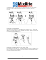
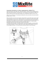
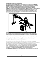
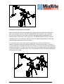
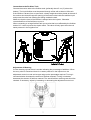
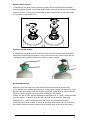
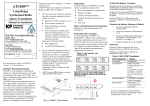
User's Manual
MixRite TF 10
Edition 05.08
1
Tefen MixRite TF 10 fertilizer and chemicals Injector
Congratulations on your purchase of one of Tefen’s high quality products.
To get the best results from the MixRite TF-10 Proportioning Dosing Injector it is
important to spend a few minutes reading carefully the explanations and
recommendations in this user's manual.
Operating the Injector
The proportioning dosing injector is fitted on the water line. The flow of water passing
through the injector activates it and causes the pumping of liquid fertilizer (or other liquid
additive) and injects it in a relative quantity into the water line.
The MixRite TF 10 proportioning dosing injector will operate in the following conditions:
The flow rate of the water passing through the injector is
Between 0.5 and 10 m3/hour (2 and 45 GPM).
The water pressure is between 1 and 8 bar (14.7 and 120 PSI).
The water & air temperatures are not less than 4ºC and not more than 40ºC. (39ºF and
not more then 104ºF)
Head loss: Low flow 0.1 Bar – High flow 0.9 Bar
The flow rate of the fertilizer and chemical can be adjusted relative to the flow rate of the
water in the range of
0.1% to 1% for Model 01
0.2% to 2% for Model 02
1% to 5% for Model 05.
Installing the Injector
Check that Injector package contains the following items:
One proportioning dosing injector to which are attached two couplings (Plasson) for a
50 mm. PE pipe or two BSPT 1½” or NPT1½” threaded couplings according to the
model.
One flexible suction tube to which is attached a flat seal and a filter.
One stand that includes 4 feet and 2 brackets (optional)
One User's manual
To fit to a wall – connect one of the brackets to the wall by inserting 4 screws in the
bracket holes.
2
To install the stand – insert the brackets to the grooves of the body at the bottom
and press up until they fit in place. Place the legs in the holes and press until
they lock.
Connection of the suction tube
Insert the flat seal into the nut of the coupling on the end of the tube (1). Thread and
tighten the nut to the inlet valve on the underside of the injector. Make sure that the nut
is threaded and tightened properly (2, 3).
Connection of the Injector to a 1½” line - MixRite TF 10
Note the direction of the water flow. Place the injector so that the arrow stamped on the
body of the injector and the red arrow point in the direction of the water flow. Connect
the injector using the plastic couplings.
3
Connection of the Injector to a 50 mm. polyethylene line - MixRite TF 10
Note the direction of the water flow. Place the injector so that the arrow stamped on the
body of the injector and the red arrow point in the direction of the water flow. Make sure
that the ends of the entry pipe and exit pipe are cut straight and that the end is in the
shape of a rounded cone. The distance between the entry end and the exit ends should
be about 20 cm. (7.87")
Remove the 50 mm nut from the injector and the white ring and slide them onto the pipe
at a short distance from the end. Check that there is an accessory seal 50 and that the
sealing 50 fixture closes the unit from outside. 1) Insert the pipe into the entry opening or
exit opening in accordance with the direction indicated and push it so that the pipe
penetrates, passes the seal and stops at the end of the track.
To facilitate the penetration of the pipe spread a little silicone grease on the end of the
tube before inserting it. Push the white ring in until it reaches the thread (2). Close the
nut and tighten securely. In the same way connect the injector to the other pipe.
4
Installing the injector on an irrigation line
It is recommended to fit a main valve(1) at the beginning of the line as well as backflow
a
prevention valve (3).
3 On a drinking water line, according to local regulations, it is obligatory
to install a backflow prevention valve to prevent entry of chemicals into the drinking
water. Then as shown in the diagram the following have to be installed: A pressure
reducer(4) to protect the injector from excess pressure, a filter (2) of at least 75 mesh, a valve (6)
before entry to the injector vacuum valve(7)to prevent siphoning when the injector is not
operating, and valves to the feed lines have then to be installed. It is advisable to add a
bypass pipe through which the water can flow to allow irrigation without fertilizer or when
it is required to dismantle the injector.
Installation of the injector on a bypass line
It is necessary to fit the proportional dosing injector to a bypass line when irrigating with
a flow rate higher than the maximum recommended for the injector. The bypass enables
only part of the water flow to pass through the bypass and activate the injector, while the
remainder passes through the main line. Using the choke valve (7) on the main line, the flow
of water passing through the main line is regulated so that the rest of the flow passes
through the bypass and activates the injector. The metering must be calculated in
accordance with the flow rate passing through both lines.
It is necessary to fit a main valve (1)at the beginning of the line and after it a backflow
prevention valve (3),pressure reducer(4),a water filter(2)of at least 75 mesh, a T connection (A)
for diversion from the main line to the bypass, a valve on the bypass before the inlet to
the proportioning dosing injector, a valve after the outlet from the injector (9)on the bypass,
and a T-connector for the return to the main line.(B). A choke valve, preferably an angled
valve, should be fitted on the main line between the bypass junction and the return
connection, to regulate the flow rates between the main line and the bypass.
An anti vacuum valve (8)should be fitted together with valves for the branch lines after the
return connection from the bypass.
5
Installation of two injectors in parallel
When the water flow rate in the irrigation line is higher than the maximum nominal flow
rate of the injectors, the water may be divided between two injectors. If the 2 injectors
are used for pumping the same type of fertilizer, the scales should be adjusted in an
identical manner to the same level of metering. Two different additives may be metered
at different levels. The metering in each unit must be calculated separately for each flow
rate passing through each of the two injectors.
It is necessary to fit a main valve(1)at the beginning of the water line and after it, a
backflow prevention valve(3),a pressure reducer(4), a filter(2) with at least a 75 mesh. A
T-junction(5)is then fitted from the main line into 2 lines. To each of these lines are fitted a
regulation valve (6), the injector, and a non-return valve immediately after the injector(7)and
a connection back to the main line (8). Care must be taken to ensure that both branches are
exactly the same length.
.
6
Connection to the Fertilizer Tank
Connect the suction tube to the fertilizer tank (preferably about 5 cm (2") above the
bottom). The liquid fertilizer must be passed through a filter with at least a 120 mesh.
If the fertilizer is drawn from an open tank, a heavy weight should be placed at the end of
the suction tube that will keep the opening of the suction tube inside the additive liquid
and prevent the tube from floating and falling outside the tank.
Make sure that the level of the fertilizer is always below the injector. Otherwise
uncontrolled flow of the fertilizer may occur.
When connecting to a large fertilizer tank use a valve that is not affected by the fertilizer
and an N.C. valve to prevent the siphon effect. The valve will only open when there is
water pressure in the irrigation line.
Adjustment of Metering
On the metering cylinder there is a scale indicating the percentage of additives. When
the entry valve is closed and there is no water pressure in the injector turn the
adjustment control nut and set its upper edge on the percentage required. Turning it
counterclockwise increases the amount of fertilizer metered. Turning it clockwise
decreases the amount of fertilizer metered. The actual fertilizer metering rate should be
checked. If necessary, adjust by increasing or decreasing the adjustment control nut.
7
Manual On/Off Control
In models with a manual on/off control the suction can be controlled while the water
flows through the injector. Turning the on/off handle clockwise to the end of the threads
stops the suction. Turning the on/off handle counter clockwise till it is fully open starts
the operation of the suction unit.
Hydraulic On/Off Control
In models with a hydraulic on/off control the suction can be controlled while the water
continues to flow through the injector, using a connection to the control tubes that are
controlled by the irrigation computer by means of electric valves.
Routine Maintenance
Regularly clean the water filter at the injector inlet and the fertilizer suction filter.
If it is planned not to operate the injector for a long period, operate the injector for a few
minutes with the metering tube immersed in a tank with clean water to remove fertilizer
residues from the injector preventing them solidifying in the injector.
If there is a fear of frost, and the temperature falling below 4° C° (39ºF), empty the water
from the injector. To do this, close the entry and exit valves securely. Open and
dismantle the 1” record nut that connects the suction pipe. Press the backflow
prevention valve using a finger or a thin rod, allowing all the water that has collected in
the injector to drain out while pressing the air release valve at the top of the injector
8
Troubleshooting Guide
Problem
Check
The injector does not
The injector is fitted with the arrows in the
work
opposite direction to the water flow.
Solution
Fit the injector with the arrows in
the direction of the water flow.
The inlet and outlet valves are closed.
Open the valves
The inlet filter is blocked.
Clean the filter.
There is no water flow at the appropriate
Open the main valve.
pressure.
The injector has
There is no water flow at the appropriate
stopped working
pressure. Open the main valve. Open the nut
Replace the motor seals.
locking the motor cover, remove the motor
cover, and remove the mechanism. Check if
the motor seals are defective.
Check if the springs are broken.
Replace the springs.
Check if the seals above the valves are
Replace the seals.
defective or have been displaced.
Check if one of the parts of the mechanism
Replace the broken part.
is broken.
There is a leak from
The leak is from the connection between the
Open and remove the motor
the injector.
body and the cover.
cover, replace the seal, fit the
cover, and thoroughly tighten the
cover locking nut.
The leak is from the connection of the
Remove the suction tube, replace
suction tube.
the defective seal and reconnect.
The leak is from the non-return valve.
Dismantle the non-return valve
and replace the defective seal.
There is no suction.
The suction filter is blocked.
Clean the filter.
Dismantle the injector unit and check if the
Replace the suction seal.
suction seal is defective.
The non-return valve is defective.
Replace the non-return valve.
For advice, technical support and purchase of spare parts, contact the authorized
sales representative in your area.
9