1
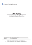
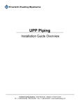
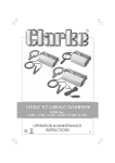
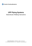
UPP Piping
Installation Guide Overview
Manual #
408001016
Revision
4
Date
Oct. 2014
Changes from Previous Revision
Show EVOH pipe lining for both EN / UL
Franklin Fueling Systems • 3760 Marsh Rd. • Madison, WI 53718 USA
Tel:  +1 608 838 8786 • 800 225 9787 • Fax: +1 608 838 6433 • www.franklinfueling.com
Safety
Important!
UPP Systems must only be installed by fully trained and certified installers.
Failure to follow installation instructions will invalidate warranty and installer
certification!
Piping Installation Safety
• UPP Welding Units must never be operated
in Zone 1 or Zone 0 areas (Hazardous area
definitions are from European Directive 1999/92/
EC and guidelines can be found in the APEA Blue
Book 3rd Edition).
• Ensure Welding Units are connected to a power
supply that meets the requirements detailed in the
user manual and are within the requirements of
any local authority or regional legislation.
• Important to any type of piping system is
to safely connect all metallic components
to ground. Metallic components, and more
general conductive materials, due to their high
capacitance, can have the potential to store high
amount of electrostatic energy (sparks discharge
can only be observed over conductive elements).
• All exposed metal parts used in UPP System
installations should be adequately grounded to
a dedicated earth electrode and brought to a
potential equal to that of other metal parts in the
close proximity.
Chemical Safety
• Where using chemicals (such as Acetone) during
the installation of UPP systems products, follow all
safety guidelines given on the chemical containers
themselves or on any accompanying literature.
2
Confined Space
• Some installation of UPP products may occur
in confined spaces where a lack of oxygen and
a concentration of toxic vapors is likely to be
experienced.
Such working conditions are dangerous and all local
health and safety guidelines for working in such
environments should be followed.
Material Handling
Protective Equipment
• Ensure the correct personal protective equipment
(PPE) is used at all times in line with local health
and safety requirements.
Material Safety Data
• Ensure all safety data is accessed and used while
installing UPP Systems (Material Safety Data
Sheets are available in the download area of the
UPP website).
Transport & Storage
• UPP products should be transported and stored in
accordance with the guidelines contained in this
manual.
Heavy items
• Heavy items should be handled using suitable
lifting equipment operated by authorised
personnel.
Figure 1: Installation Overview
Contents
Safety.................................................................2
Introduction.......................................................3
Underground Fuel Pipe Construction............... 3
Transit, Off-loading and Storage.....................4
Uncoiling Pipe................................................... 4
Site Preparation................................................5
Pipe Burial Guidelines.....................................5
Pipe Bend Radius............................................. 6
Completion Records......................................... 6
Pipe Detector Tape........................................... 7
Pressure Testing...............................................7
Testing Guidelines. .......................................... 7
UPP Recommended Pipe Test Procedure....... 8
Hydrostatic Pressure Testing Method............... 8
UPP Pneumatic Tightness Testing
Method Procedure............................................9
Sump Inspection Register.............................10
Underground Fuel Pipe Construction
Black outer structural layer of the pipe is High Density
Polyethylene (HDPE), grade PE80 or PE100 which
allows the use of electrofusion couplers and fittings to
construct a variety of pipeline configurations. HDPE PE80
and PE100 has well proven resistance to: stress cracking,
puncture, scratch, impact, microbial and rodent attack.
The intermediate tie-layer causes a permanent bond to
occur between the polyethylene and the liner material.
The liner of UPP primary pipe is a specially formulated
“fuel proof” barrier layer manufactured from either EVOH
(EN / UL) or Nylon (UL). Both liners have exceptional
resistance to absorption and permeation of both
hydrocarbon and alcohol fuel blends.
The smooth bore and low friction loss of UPP pipe
permits higher fuel and vapor flows than steel pipe,
reducing the pumping energy costs.
UPP underground fuel pipe is pressure rated to 10 bar
(EN) or (90 psi) to UL971. Rupture pressure is typically
exceeding 40 bar (580 psi) providing a large margin of
safety.
Carrier - PE - Black
Introduction
Underground Fuel Pipe Systems
Several types of underground fuel pipe are available for
different applications and to meet various engineering
and legal requirements:
• U
PP primary pipe a fuel-proof liner for product,
suction, pressure, vapor vent and fill lines.
• UPP Secondary containment pipe used with
EN primary pipe – for pressure systems or
environmentally sensitive sites.
• U
PP Integral Secondary Containment pipe
(UL971 spec) — for pressure systems or
environmentally sensitive sites.
• U
PP electrical conduit pipe — for underground
electrical wiring protection.
• UPP Electrical duct — for underground electrical
wiring protection.
UPP piping systems are designed in various diameters,
from 32-160 mm (I"- 6") for the transfer of fuels in filling
station forecourts, marinas, and airports. UPP systems
are also used for government and military installations
as well as many industrial sites such as mines and rail
depots.
There is no requirement for a concrete trench because
fusion welded HDPE pipe is structurally resistant to
weight of backfill material and dynamic traffic loads. Over
30 years experience showing no failures in underground
fuel pipe systems and no loss into the ground.
Tie Layer
Liner - EVOH -clear (EN / UL)
Nylon - Yellow (UL)
Figure 2: UPP Pipe Structure
Pressure Ratings
Pressure Rating (UL 971)
Pipe type
UPP Primary
UPP Secondary
Pressure
Rating (Bar)
Pressure
Rating (PSI)
6.2
90
5
72.5
Table 1: UL971 Pipe Maximum Pressure Rating
Pressure Rating (EN14125)
Pipe type
Pressure
Rating (Bar)
Pressure
Rating (PSI)
UPP Primary
10
145
UPP Secondary
5
72.5
Table 2: EN14125 Pipe Maximum Pressure Rating
3
Transit, Off-loading and Storage
Although UPP polyethylene pipe and fittings are
extremely hard wearing and resilient, it is important to
handle and store them with care to prevent scuffing or
gouging. Any damaged pipes may need to be rejected
and not installed.
UPP products should be transported in a flat-bedded
vehicle, free from sharp objects and projections. Wide
polypropylene slings must be used when lifting pipe
crates by crane. Avoid using chains, hooks or hawsers.
A spreading beam should be used when lifting crates
containing pipe lengths greater than 6 m (19 ft 8")
• U
PP fittings - all electrofusion fittings are packed
in heat-sealed polyethylene bags and delivered
in cardboard cartons. Fittings should be stored in
their packaging and in a dry area, away from direct
sunlight, until ready for use. This is particularly
important for electrofusion fittings. These must be
kept in their packaging until ready for use to prevent
any contamination or oxidation.
Uncoiling Pipe
• Allow for a slight bending of the pipe crates when on
and off-loading.
• S
tandard 6 m (19 ft 8") crates may be moved using
a forklift. A side loader fitted with a minimum of four
supporting forks should be used for longer lengths.
Otherwise use a crane fitted with a spreader beam.
• W
hen using a forklift to on or off-load coils, the forks
should be covered to avoid damage to the coiled pipe.
Figure 4: Uncoiling Pipe
The pipe can straighten with
considerable force. Take care when
releasing pipe from the coil and
secure the straightened pipe.
Let the pipe rest in its uncoiled state for about eight
hours. High ambient temperatures can reduce this
“layout” time and low temperatures may increase it.
Pipe can be laid in its final position to “relax” before
connecting up.
Caution
Figure 3: Moving Coils
Storage on site
• Individual pipe lengths should be stacked not
more than 1 m (3 ft) high with the bottom layer fully
restrained by wedges. The bottom layer of pipes
should be laid on timber battens at 1 m (3 ft) centres
to avoid any damage from sharp objects lying on the
ground.
• P
ipe crates should be stored on clear, level ground and
should never be stacked more than three crates high.
• C
oils should be stored on firm level ground that has
suitable protection for the bottom of the coil. Stacked
coils should never exceed three coils high. Individual
coils should be stacked flat. If stored on edge, they
must be secured against a properly anchored support
and stored like this for a short period of time only,
particularly in warm weather conditions.
• B
adly stacked coils and pipe lengths can slip causing
personal injury or damage to the product. Facilities for
safe lifting and moving must be available.
• P
ipes are supplied with distinctive colored end caps
to prevent entry of any contamination. These end
caps must be kept in place during storage.
4
• You need at least two people to uncoil and cut the
pipe. The coil is taped up in layers to make it easier
to uncoil at manageable intervals.
• The area in which the pipe is uncoiled on site must be
clear, safe and free of sharp objects.
• R
emove the tape around the tail end on the outer
winding and secure this end.
• W
ith the coil in the vertical position, roll the coil out
cutting and removing tape as you find it (ensuring to
release only the next turn of pipe in the coil).
• D
o not drag the pipe.
• The natural curves from coiling can be used to
change pipe direction and bags of sand, pea gravel or
stakes can be used to hold it in place until it is ready
for connecting.
• O
ne person should hold the pipe whilst another cuts it
to the desired length.
• The cut ends will have a prominent hook that can be
partially removed when weight is placed on it (bags
of sand or pea gravel), or use the hook end to your
advantage when turning direction into a chamber or
pump sump.
Site Preparation
Site inspection:
Make sure the site is prepared and ready. The tanks,
sumps, fill points, vents etc. should be in place
IMPORTANT!
The site should be free from previous
fuel contamination.
Pipe Burial Guidelines
Recommended burial depth of UPP pipe is a minimum of
300 mm (12").
• All trenches should be sloped back towards the
storage tanks. The fall back (slope) for all pipework
to the tank chambers should be a minimum of 1 m
every 100 m or 1/8" per foot (Figure 7). This may vary
to meet local requirements. The position of the entry
fittings at the furthest dispenser sump away from the
tank chambers may be considerably higher than that
of the entry fittings on the closest dispenser sump.
• V
apor return lines should have a slope of 2 m every
100 m (1/4" per foot) and never less than 1 m every
100 m (1/8" per ft.) back towards the tank farm, unless
in-line joints such as elbows are to be used.
• Trench corners should have a radius of 1.5 m (5 ft).
• A recommended 15 cm (6") bed of backfill material
should be laid underneath the pipe prior to installation
and there must never be voids under or around the
pipe. Acceptable backfill materials are:
• W
ell-rounded pea gravel size 3 mm (⅛") to
20 mm (¾")
• C
rushed rock size 3 mm (¾") to 16 mm (5/8")
• Clean washed sand
• Backfill material must not be contaminated with
any petroleum product or other contaminant
Figure 5: Pipe Spacing
• W
hen laying duct onto a concrete base a 150 mm (6")
thick bed of compacted sand should be laid on the
concrete, below the duct. (The minimum amount of
sand should be 50 mm (2") of compacted sand)
• All beds should be laid so that the pipe will not dip or
sag when it is installed.
• L
aying of pipe should start from the tank farm.
• U
nderground pipe runs may be continuous or have
electrofusion welded joints. Any mechanical joints
or compression fittings must be located within a
containment chamber or sump.
Figure 6: Electrofusion Welded Fitting Detail
Refer to FFS manual 405001007 for information about
the electrofusion process.
1:100 Fall-back (Slope) to tank
Figure 7: Fall-back (slope) to Tank
5
• U
PP pipe exceeding 12 m (39 ft) should be laid in a
series of large snake-like curves and not in straight
lines. Uncoiled pipe, when laid, will settle in a natural
curve.
• If used above ground, UPP pipe should be protected
against mechanical, climatic damage. Additional
supports and anchor points may also be required.
Check fire codes for proper installation. Also see
document FFS-0134, UPP Piping Above Ground and
Marina Installations.
• M
ark positions on the tank access chamber/sump for
penetration locations and install UPP seals.
Bend Radius
The UPP piping systems have a semi-rigid construction
which gives both strength and flexibility.
Figure 9: Bend Radius
Figure 8: Using Temporary Stakes to Snake Pipe
Refer to Table 1 for allowable bend radius of UPP Pipe.
• G
enerally any thermal expansion will be accounted
for by following our guidelines for spacing, backfilling
and ensuring runs are “snaked”.
• P
ipes should be separated from each other by at
least the diameter of the largest pipe.
• If pipe-runs cross each other they must be separated
by at least as much backfill material as the diameter
of the largest pipe or protected using at least 25 mm
(1" ) of expanded polystyrene (Styrofoam™).
Important:
Completion Records
• O
n completion of UPP installation make an “as
constructed” drawing showing the exact location
of all below ground lines. It is also recommended
that, in addition, a photographic record is
preserved.
Pipe Bend Radius
Single Wall Pipe
Temperature
32 mm (1 ") 50 mm (1½") 63 mm (2") 90 mm (3") 110 mm (4") > 15˚C (>59˚F)
0.5m (1 ft 7")
0.75 m (2 ft 6")
0.9 m (3 ft)
2.25 m (7 ft 4")
2.75 m (9 ft)
0 - 15˚C (32 - 59˚F )
0.8 m (2 ft 7")
1.25 m (4 ft 1")
1.58m (5 ft 2")
3.15m (10 ft 4")
3.85m (12 ft 8")
< 0˚C (< 32˚F)
1.12 m (3 ft 8")
1.75 m (5 ft 9")
2.2 m (7 ft 3")
4 m (13 ft 2")
4.9 m (16 ft)
Double Wall Pipe
Temperature
40/32 mm
(1 ") 63 / 50 mm
(1½")
75 / 63 mm
(2")
110/90 mm (3")
125/110 mm
(4")
> 15˚C (> 59˚F )
0.6 m (2 ft)
0.9 m (3 ft)
1.12 m (3 ft 8")
2.75 m (9 ft)
3.1 m (10 ft 2")
0 - 15˚ C (32 - 59˚F)
1 m (3 ft 3")
1.5 m (4 ft 11")
1.88 m (6 ft 2")
3.85 m (12 ft 8")
4.4 m (14 ft 5")
1.4 m (4 ft 7")
2.2 m (7 ft 3")
2.6 m (8 ft 6")
4.9 m (16 ft)
5.6 m (18 ft 4")
< 0˚C (< 32˚F)
UL971 Pipe
Temperature
63 mm (2")
90 mm
(3")
63 / 50 mm
(1½")
75 / 63 mm
(2")
110 / 90 mm
(3")
125 / 110 mm
(4")
1 m (3 ft 3")
3 m (9 ft 10")
1 m (3 ft 3")
1 m (3 ft '3")
4 m (13 ft 2")
4 m (13 ft 2")
0 - 15˚C (32 - 59˚F)
1.6 m (5 ft 3")
5 m (16 ft 5")
1.6 m (5 ft 3")
1.6 m (5 ft 3")
6 m (19 ft 8")
6 m (19 ft 8")
< 0˚C (< 32˚F)
2.2 m (7 ft 2")
7 m (23 ft)
2.2 m (7 ft 2")
2.2 m (7 ft 2")
8 m (26 ft 3")
8 m (26 ft 3")
> 15˚C (> 59˚F)
Table 3: Allowable Bend Radius
6
Pipe Detector Tape
UPP Detectable tape is used to allow the piping location
to be found after it has been covered. The tape is installed
below ground at 250 mm (9.8 inches) height directly
above pipe runs to indicate the position of each pipe.
Pressure Testing
Following inspection, prior and subsequent to backfilling,
a tightness test should be carried out by a competent
person on each pipe run, chamber and sump to verify
the integrity of joints and seals. This testing should meet
the requirements of local officials and engineers and
comply with local health and safety regulations.
The following testing procedure is suggested for
guidance only and should in no way override oil
companies or local regulator’s requirements.
Detector Tape
Testing Guidelines.
Max Depth
Detection 3 m
Pea Gravel
or Sand
250 mm
Subsoil
UPP Pipe
Figure 10: Detector Tape Installation
Both ends of the tape should be grounded during
installation.
End of Tape Must be Grounded in Sumps
Figure 11: Detector Tape must be Grounded
When using a detection tool, the near end of the
detectable tape should be disconnected from the
grounding point to allow the red cable from the
transmitter to be connected to the tape and the black
cable from the transmitter to be connected to the
grounding point.
The far end of the tape should remain grounded to give
the highest signal strength and the earth spike should
be as far away from the trace path as possible at a 90
degree angle.
Use the lowest frequency possible from the transmitter
around 577 Hz or 8 KHz to eliminate coupling to other
grounded cables.
Use the receiver to follow the path of the tape to
locate the buried pipe. Follow direction included with
the receiver and transmitter for detecting buried pipe
location.
Equipment
• Target test pressure should be 50% of scale on
gauge, e.g. if the test pressure is 1 Bar (14.5 psi) ,
use a 2 Bar (29 psi) gauge.
• G
auges should have serial numbers and be tested /
certificated yearly.
• P
ressure testing equipment should have fitted a relief
valve set at around 0.5 bar (7.25 psi) above the test
pressure.
General Guidelines
• W
hen applying pressure from gas cylinders, use
suitable valves to ensure test pressure is not
exceeded.
• Apply pressure or vacuum slowly to minimise risks.
• W
hen tightness testing primary pipe the secondary
should be open to atmosphere this is critical
whenever secondary pipe is filled with liquid.
• S
econdary pipe should ideally not be welded prior to
testing primary to allow inspection of joints.
• W
hen tightness testing secondary pipe the primary
should be open to atmosphere.
• W
ipe each joint with soapy water to check for leaking.
Caution
• To avoid explosion hazards, nitrogen or an inert gas
from a pressure cylinder should be used in place of
compressed air for tightness testing if fuel has been
used to ballast underground storage tanks or if pipework has previously contained petroleum.
• P
ipe-work should be disconnected (isolated) from
underground storage tank prior to commencing
tightness testing.
• Any water used for testing should be disposed of
through the oil / water separator or by a specialist
contractor and in accordance with any local
environmental health and safety requirements and
regulations.
There are two recommended tightness test methods for
UPP pipe-work; hydrostatic and pneumatic.
In all instances the hydrostatic method is to be preferred
as it allows high pressures to be used with relative safety.
However, there will be instances where the introduction
of water into the pipe-work is undesirable, in these
cases the pneumatic method should be adopted paying
particular attention to the safety aspects of working
with compressed gas due to the high levels of potential
energy that can be stored.
7
UPP Recommended Pipe Test Procedure
Primary Pipe Hydrostatic Pressure Testing
Method
Equipment
• P
ump rated for more than 10 bar (145 psig)
• H
ydrofor (reservoir or pressure tank)
• Two pressure gauges, rated for 12 bar (174 psig),
min. reading 0.1 bar (2 psig)
• Check valve
• Ball valve
• P
ressure relief valve rated for 20 bar (290 psig), set
at 11 bar (159 psig)
Conditioning Phase
• Fill the pipe work system to be tested with water,
making sure that any air relief valves are opened
while filling the pipe work.
• After filling the pipe work wait 1 hour for the
temperature to stabilize.
• P
ressurize the system to 10 bar (145 psi) and
maintain this pressure for 30 minutes. (System
pressure shall be maintained by means of refilling in
order to compensate for the increase in volume due
to the expansion of the pipe-work). At this time the
system should be thoroughly inspected for leakage.
After any such areas have been remedied repeat the
conditioning before proceeding to the testing phase.
Testing Phase
• R
apidly reduce the system pressure to 3 bar (43.5
psi) by bleeding water from the pipe-work. (Due to the
visco-elastic properties of polyethylene the pipe will
contract).
• D
uring the test period of 90 minutes the pressure
should be recorded with the frequency shown below:
Test period
(mins)
Frequency of
readings (mins)
Number of
readings
0-10
2
6
10-30
5
4
30-90
10
6
Table 4: Recording Test Results
• The test is passed if all the readings during the
testing cycle are 3 bar (43.5 psi) or above.
• D
ecreasing readings = failure of pressure test. (Note
that the readings are likely to increase).
• If the system fails the pressure test make the
following checks:
• Check all mechanical connections
• C
heck welded joints
• W
hen the failure point has been located and
remedied repeat the full conditioning and testing
sequence.
Maintain 145 PSI (10 bar) for 30 minutes
Pressure PSI (bar)
145 (10)
130.5 (9)
116 (8)
101.5 (7)
87 (6)
72.5 (5)
58 (4)
43.5 (3)
29 (2)
14.5 (1)
0
8
drop to 43.5 PSI (3 bar) for 90 minutes
To Pass Test Pressure Must remain at 43.5 PSI (3 bar) or above
0
10
20
30 0 2 4 6 8 10 15 20 25 30
40
50
60
Conditioning Time (mins)
Test Reading Times (mins)
Hydrostatic Testing Graph
70
80
90
UPP Pneumatic Tightness Testing
Procedure
The following testing procedure is suggested for
guidance only and should in no way override oil
companies or local regulator’s requirements.
Never exceed the pressure ratings of components
shown on Table 1: & Table 2: on page 3 of this document
when testing.
Test Procedure
• Record Temperature and Pressure at start of each
test time.
• Condition and test the piping as follows:
1. Pressurise the piping to 10% of test
pressure, hold pressure for 30 minutes and
inspect for leakage or pressure drop.
2. Increase pressure to 50% of test pressure
and again inspect for leakage while holding
pressure for 30 minutes.
3. Increase pressure to 100% of test pressure
and again inspect for leakage while holding
pressure for 30 minutes.
• Record Temperature and Pressure at end of each
test time.
• If results are within criteria of Table 6 Tightness Test
is passed.
Pressure Testing Safety
Follow these guidelines when conducting pneumatic
testing:
• Wear Safety glasses.
• Relieve air pressure before any corrective actions are
taken.
• Allow only necessary and authorized persons in the
proximity of pipe being tested.
• Restrain the movement of connections, joints and
seals during testing.
Recommended Pipe Tightness Testing
Pressure
Pipe Type
Bar
PSI
Primary pipe
3.5
50
Secondary pipe with
Welded Reducers
Secondary pipe with
Rubber Reducers
3.0
44
0.5
7
Table 5: Recommended Pipe Tightness Testing Pressures
Acceptable Pressure Variation
Initial Pressure 3.5 bar
Temperature variation Δ T (°C)
-15
-10
-5
0
5
10
15
Final pressure due to temperature change (bar)
3.27
3.35
3.42
3.50
3.58
3.65
3.73
Initial Pressure 50 psi
Temperature variation Δ T (°F)
-30
-20
-10
0
10
20
30
Final pressure due to temperature change (psi)
46.3
47.6
48.8
50.0
51.2
52.4
53.7
Initial Pressure 3.0 bar
Temperature variation Δ T (°C)
-15
-10
-5
0
5
10
15
Final pressure due to temperature change (bar)
2.80
2.86
2.93
3.00
3.07
3.14
3.20
Initial Pressure 44 psi
Temperature variation Δ T (°F)
-30
-20
-10
0
10
20
30
Final pressure due to temperature change (psi)
40.7
41.8
42.9
44.0
45.1
46.2
47.3
Initial Pressure 0.5 bar
Temperature variation Δ T (°C)
-15
-10
-5
0
5
10
15
Final pressure due to temperature change (bar)
0.42
0.45
0.47
0.50
0.53
0.55
0.58
Initial Pressure 7 psi
Temperature variation Δ T (°F)
-30
-20
-10
0
10
20
30
Final pressure due to temperature change (psi)
5.8
6.2
6.6
7.0
7.4
7.8
8.2
Table 6: Acceptable Pressure Variation
9
Sump Inspection Register
Date of Inspection or Test Results of Inspection or Test
Signature of Inspector or
Tester
Required Monthly And/Or Annual Inspection: Containment sumps located on the property at which the FFS products are installed must be visually inspected for liquid
monthly. Sump sensors, if installed, must be tested annually. Any leaks must be corrected at the time they are found.
Recommended Monthly Inspection: Verify sump lids are tight and sealed. Inspect sumps for dirt, debris, liquid or any physical cracks or holes that would allow leakage.
Check for evidence of staining or new staining. Verify penetration boots are in good condition and the pipe entry into the sump is positioned properly (near perpendicular
entry). Verify sump liquid sensors are positioned correctly if installed. Verify the piping and other equipment in the sump are in good condition.
Record any faults on this Sump Inspection Register and have the fault(s) corrected at the time found.
Additional copies of this form can be downloaded from the FFS website www.franklinfueling.com
End user proprietary inspection check register log formats or any form to record these inspections is acceptable.
10
From FFS form FFS-0131 Rev1
Franklin Fueling Systems • 3760 Marsh Rd. • Madison, WI 53718 USA
Tel: +1 608 838 8786 • 800 225 9787 • Fax: +1 608 838 6433 • www.franklinfueling.com
Page Intentionally Blank
11
www.franklinfueling.com
3760 Marsh Road
Madison, WI 53718, USA
Tel: +1 608 838 8786
Fax: +1 608 838 6433
USA & Canada Tel: 1 800 225 9787
México Tel: 001 800 738 7610
Brazil Tel: +55 11 3395 0606
UK Tel: +44 1473 243300
Franklin Fueling Systems Gmbh
Rudolf-Diesel-Strasse 20
54516 WITTLICH, Germany
Tel: +49 6571 105 380
Fax: +49 6571 105 510
France Tel: +49 6 57 11 05 380
China:Tel: +86 10 8565 4566
Fax: + 86 10 8565 4766
A802, ChaowaiMEN Center
No. 26 Chaowai Street
Chaoyang District
Beijing 100020, China
©FFS 2014 408001016 Rev 4