1
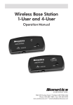
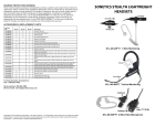
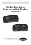
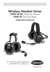
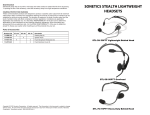
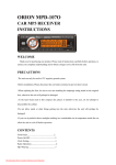
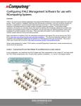
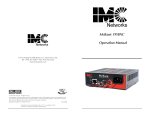
Wireless Base Station
1-User and 4-User
Operation Manual
C O R P O R AT I O N
7340 SW Durham Road • Portland, OR 97224 USA
Phone: 503-684-7080 • Fax: 503-620-2943
www.soneticscorp.com • email:[email protected]
TABLE OF CONTENTS
Base Station Models . . . . . . . . . . . . . . . . . . . . . . . . . . . . . . . . . . . . . . . . . . . . 2
Installation . . . . . . . . . . . . . . . . . . . . . . . . . . . . . . . . . . . . . . . . . . . . . . . . . . . 3
Pairing . . . . . . . . . . . . . . . . . . . . . . . . . . . . . . . . . . . . . . . . . . . . . . . . . . . . . 4-6
Troubleshooting . . . . . . . . . . . . . . . . . . . . . . . . . . . . . . . . . . . . . . . . . . . . . . . 7
Specifications . . . . . . . . . . . . . . . . . . . . . . . . . . . . . . . . . . . . . . . . . . . . . . . . . 8
Package Contents
.............................................9
Warranty . . . . . . . . . . . . . . . . . . . . . . . . . . . . . . . . . . . . . . . . . . . . . . . . . . . . . 9
1
BASE STATION MODELS
LINK
WIRELESS BASE
POWER
INTERCOM
PAIR
Single Headset Base Station
112-3089-0E
LINKS
WIRELESS BASE
POWER
1 2 3 4 5
INTERCOM
PAIR
Multiple Headset Base Station
112-3086-0E
LINK
WIRELESS BASE
10 Series
POWER
INTERCOM
PAIR
Single Headset Base Station
112-3094-0E
P
P
LINKS
WIRELESS BASE
1 2 3 4 5
10 Series
POWER
INTERCOM
PAIR
Multiple Headset Base Station
112-3095-0E
2
1-User Base Station, 30XXR Intercom
Compatible
This model accommodates a single Sonetics
radio transmit wireless headset or single wireless
belt pack. The base station can be connected
via a 6 conductor flat cable to any headset
port in Firecom’s 30XXR series intercoms. The
base station will provide full duplex audio and
PTT communication between the wireless headset or belt pack and the intercom.
4-User Base Station, 30XXR Intercom
Compatible
This model accommodates up to five Sonetics
non-radio transmit wireless headsets1 or wireless
belt packs.The base station can be connected
via a 6 conductor flat cable to any headset port
in Firecom’s 30XXR series intercoms. The base
station will provide full duplex audio communication between the wireless headsets or belt
packs and the intercom.
1-User Base Station, Sonetics, 10 Series
Intercom Compatible
This model accommodates a single Sonetics
radio transmit wireless headset or single wireless
belt pack. The base station can be connected
via a 6 conductor flat cable to any headset
port in Sonetics’ 10 Series intercoms. The base
station will provide full duplex audio and PTT
communication between the wireless headset
or belt pack and the intercom.
4-User Base Station, Sonetics, 10 Series
Intercom Compatible
This model accommodates up to five Sonetics
non-radio transmit wireless headsets1 or wireless
belt packs.The base station can be connected
via a 6 conductor flat cable to any headset
port in Sonetics’ 10 Series intercoms. The base
station will provide full duplex audio communication between the wireless headsets or belt
packs and the intercom.
INSTALLATION
• It is recommended that the base station be mounted high inside the vehicle,
not within 10.2cm of any metal3. The base station should be attached to a flat
surface with 6.35mm thick, double-sided tape, to help insulate the base station
from the cold. When mounted vertically, the base station should be oriented so
that cables into the base station are connected from the bottom, not the top of
the enclosure so as not to provide a water path into the enclosure. Mount the
base station in a location that ensures at least 1.07cm of distance from all users.
• Connect nominal 12V (11-16V) from the vehicle to the base station using the power
cable provided. The base station can be connected to the vehicle power line and
ground at any location on the vehicle, without risking undesired effects such as
ground loops, etc. Connect the black wire to the vehicle’s ground and the red
wire to the vehicle’s 12V power. When wiring to the base station follow the Fuse
Assembly Installation Instructions below.
• Plug one end of the enclosed 6P6C RJ-12 modular communication cable into the
RJ-12 jack on the base station and the other end into any headset port on the
intercom4.
NOTICE: FUSE ASSEMBLY INSTALLATION
When using a vehicle power supply to operate the base station, the power cable
assembly (420-0047-00) is connected to the fuse assembly (330-0012-00), which is
wired to one of the vehicle’s fuse box slots using a 1A ATO fuse.
Only use a 500mA fuse (supplied) in the provided fuse holder assembly.
NOTE: When crimping the 6P6C modular plugs, always make sure the
printed side of the cable is facing the release tab on the plug on both
ends of the RJ-12 modular cable.
• To provide strain relief for the power cable, use a wire tie to tie the modular
communication cable to the power cable. Place the wire tie as close to the base
station as possible.
The RJ-12 Modular Plug
Release tab
WIR
POW
ER
ELE
SS B
ASE
LINK
INTE
RCO
M
PAIR
Cable slot
3
PAIRING
LINK
WIRELESS BASE
POWER
INTERCOM
PAIR
1-User Base Station
1-User Base Station
1.When the base station is first powered, the green LED labeled POWER on the
bottom left of the front panel will illuminate steadily. The single LINK yellow LED
will either stay unlit, indicating that no headset / belt pack have been previously
paired to the base, or will start flashing rapidly, indicating that a headset / belt
pack has been previously paired to the base station5.
2.Press and hold the pairing button in the bottom right corner of the base station
for approximately 5-7 seconds. The LINK LED will start flashing slowly to indicate
that the base station has been placed in pairing mode. Once the base station is
placed in pairing mode, the user has approximately 15 seconds to place the
headset / belt pack in pairing mode.
3.Place the headset / belt pack in pairing mode; refer to the headset or belt pack
series user’s manual for pairing instructions. The red and green LEDs on the
headset / belt pack will alternate rapidly to indicate that the headset / belt pack is
in pairing mode.
4.After about 5-7 seconds, the green LED on the headset / belt pack and the yellow
LINK LED on the base station’s front panel will flash rapidly for two seconds then
turn on steadily to indicate that a link has been established between the headset / belt pack and the base. At this point, full duplex audio communication
between the headset / belt pack and the base station is enabled.
4
PAIRING
LINKS
WIRELESS BASE
POWER
1 2 3 4 5
INTERCOM
PAIR
4-User Base Station
4-User Headset Base
The 4-User base station is equipped with 5 yellow LINK LEDS on the front panel.
Each LINK LED represents a headset / belt pack position with position #1 represented
by the left-most LED. The pairing priority is given starting with position #1 and ending with position #5. It is recommended that pairing to new headsets/belt
packs is done one headset at a time.
1.When the base station is first powered, the green LED labeled POWER on the
bottom left of the front panel will illuminate steadily. Each of the five LINK
yellow LEDs will either stay unlit, indicating that no headset / belt pack has been
previously paired to any particular headset slot, or will start flashing rapidly
indicating that a headset / belt pack has been previously paired to a particular
headset slot 5 but is not currently linked.
NOTE: If any headsets/belt packs have been previously paired to the
base station and the intent is to keep them paired, then these headsets/
belt packs must remain turned on and linked in steps 1 through 3 of
this procedure. An active
P link to a headset/belt pack is indicated by the
respective LINK LED on the front panel of the base station being steadily
illuminated.
2.Press and hold the pairing button in the bottom right corner of the base station
for approximately 5-7 seconds. The respective LINK LEDs for any headset / belt
pack that is currently linked to the base station will remain steadily illuminated.
However, LINK LEDS for vacant slots and for occupied slots with no actively linked
headset / belt pack will start flashing slowly to indicate that the base station has
been placed in pairing mode and that these slots have been made available for
pairing. The highest priority slot will be assigned to the unit currently being paired.
Once the base station is placed in pairing mode, the user has approximately 15
seconds to place the headset / belt pack in pairing mode.
5
PAIRING
3.Place the headset or belt pack in pairing mode; refer to the applicable user’s
manual for information regarding how to put the unit in pairing mode. The red
and green LEDs on the headset / belt pack will alternate rapidly to indicate that the
unit is in pairing mode.
4.After about 5-7 seconds, the green LED on the unit and the respective yellow
LINK LED on the base station’s front panel will flash rapidly for two seconds then
turn on steadily to indicate that a link has been established between the unit
and the base. At this point, full duplex audio communication between the
unit and the base station is enabled.
Note: It is only necessary to pair a headset / belt pack to a base station once. After
that, if power is turned off to the headset / belt pack or base station, the pairing
settings will not be lost in either the headset or the base, as those settings reside in
permanent memory on both devices.
Footnotes
1- Five headsets / belt packs can be paired to a 4-user base station, but only four headsets / belt packs can
be connected and communicated through the base at any given time.
2- Under certain site conditions, it may be possible to operate up to 120 headsets or belt packs in close
proximity.
3- Due to the excellent coverage range the wireless system provides, the base may be mounted in different
locations inside the vehicle, such as the top surface of the dashboard close to the front windshield.
Care should be taken when the base station is mounted in such locations in order to ensure that the
base station and its wiring are not damaged due to accidental bumping or piling up of additional
working gear.
4- In the case of radio transmit 1-user base station, if transmit priority is desired, then the communication
cable from the base station should be plugged into the port marked PR.
5- If the LINK LED flashes rapidly at power up, then a headset or belt pack has been previously paired
to the base. The previously paired unit will not need to be paired again to the base station and
turning the power on to the unit will make it link to the base station.
6
TROUBLESHOOTING
When properly located, installed and powered, the base station will perform reliably
with no anticipated problems.
Note: If the symptoms you are experiencing are not covered in this manual, or if
you are having difficulty troubleshooting your system, contact your local Sonetics
dealer for assistance or see www.soneticscorp.com for additional information.
Problem: No indication of power to the base station (green power indicator does
not illuminate).
• Check wiring and fuse assembly to the base station.
Problem: No audio communication and/or PTT from or to the base.
• Ensure that power is turned on to the wireless unit(s) and that the unit(s)
are connected.
• Ensure that the modular communication cable is connected between the
base station and intercom.
• Check the modular communication cable between the base station and
intercom for continuity.
• Ensure correct polarity of the 6P6C plug on both ends of the modular cable
(refer to “Installation” section).
Problem: Poor quality audio, low or distorted received or transmitted audio.
• Ensure that the volume level is properly adjusted on the intercom. For 30XXR
series intercoms, it is recommended that the volume level is set as high as
possible on the intercom without causing distorted audio on the headset side,
and that the volume control on the headset is adjusted for comfortable listening.
• Poor quality audio can also be caused by a defective headset. Check
operation with a known, well functioning headset in order to determine
whether the problem is attributed to the base station.
• Ensure that the proper base station model for your intercom is used.
Problem: Audible interference from portable and mobile radios.
• The wireless system is tested and proven to be immune to interferences from
portable and mobile communication equipment operated anywhere in the
frequency spectrum from 30MHz to 18GHz. However, care should be taken
with installation of communication cables between the intercom and the base
station. These cables should be routed away from portable and mobile radios
and antenna cabling in order to prevent RF interference from such devices.
Problem: Poor coverage range.
• Check location of the base station on the vehicle. The base station should not
be installed inside metal enclosures or any other location closer than 10.2cm
to a metal object or surface.
• Poor range can also be caused by a defective headset or belt pack. Check
operation with a known, well functioning headset / belt pack in order to
determine whether the problem is attributed to the base station.
7
SPECIFICATIONS
Electrical:
- Power: Nominal 12V (11-16V)
- Current draw: 45mA average, 80mA peak
- Reverse voltage protection
- Immune to ESD and transients per SAE standard J1113
Mechanical:
- Dimensions: 14.48cm L x 6.6cm W x 2.90cm H
- Weight: 0.120Kg
Environmental:
- Operating temperature range: -10 to +70°C
- Storage temperature: -25 to + 85°C
- Meets SAE standards J1455
- Chemical resistance, corrosion and humidity per MIL-STD-810
RF:
- Range: 512 meters open field.
- Secured digitally encrypted interference-free communications.
- Up to a total of 120 headsets / belt pack combinations connected simultaneously
in close proximity.
Meets Essential Requirements of:
EN 301 406 V1.5.1
EN 489-6 V1.3.1
IEC 60950-1: 2005
EN 60950-1: 2006
Changes or modifications not expressly approved by Sonetics can void
the user’s authority to operate the equipment.
8
PACKAGE CONTENTS
1-User Base Station: P/N 112-3089-0E
- Power cable, 2.74 meters: P/ N 420-0047-00
- Modular communication cable, 4.88 meters: P/ N 400-0009-00
- Modular plug 6P6C, 2ct, P/ N 351-0002-07
- Fuse holder: P/ N 330-0012-00
- Adapters, power cable: P/ N 420-0109-00
- User’s manual: P/ N 600-0155-0E
4-User Base Station: P/N 112-3086-0E
- Power cable, 2.74 meters: P/ N 420-0047-00
- Modular communication cable, 4.88 meters: P/ N 400-0009-00
- Modular plug 6P6C, 2ct, P/ N 351-0002-07
- Fuse holder: P/ N 330-0012-00
- Adapters, power cable: P/ N 420-0109-00
- User’s manual: P/ N 600-0155-0E
1-User Base Station: 10 Series P/N 112-3094-0E
- Power cable, 2.74 meters: P/ N 420-0047-00
- Modular communication cable, 4.88 meters: P/ N 400-0009-00
- Modular plug 6P6C, 2ct, P/ N 351-0002-07
- Fuse holder: P/ N 330-0012-00
- Adapters, power cable: P/ N 420-0109-00
- User’s manual: P/ N 600-0155-0E
4-User Base Station: 10 Series P/N 112-3095-0E
- Power cable, 2.74 meters: P/ N 420-0047-00
- Modular communication cable, 4.88 meters: P/ N 400-0009-00
- Modular plug 6P6C, 2ct, P/ N 351-0002-07
- Fuse holder: P/ N 330-0012-00
- Adapters, power cable: P/ N 420-0109-00
- User’s manual: P/ N 600-0155-0E
ACCESSORIES
- 30XXR intercom to dual base adapter cable: P/ N 420-2142-00
- 110 / 210 intercom to dual base adapter cable: P/ N 420-2143-00
- Power supply, international wall adapter: P/ N 114-0061-0E
If a problem persists in the device, contact Sonetics for a Return Merchandise
Authorization (RMA) number. Return the device for replacement or repair.
CONTACT: Sonetics: 7340 SW Durham Road • Portland, OR 97224 USA
503-684-7080
www.soneticscorp.com • email: [email protected]
9
C O R P O R AT I O N
7340 SW Durham Road • Portland, OR 97224 USA
Phone: 503-684-7080 • Fax: 503-620-2943
www.soneticscorp.com • email:[email protected]
Copyright © 2009 Sonetics Corporation - All rights reserved.
The information in this document is subject to change without notice.
No part of this document may be reproduced in any form without prior written consent of Sonetics Corporation.
This document is part number 600-0155-0E RevA.