1
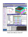
Harris
Introduction to CMOS VLSI Design (E158)
Project Staffing and Milestone Definitions: Rev 1
The project is divided into clusters with the following estimated staffing (subject to
change).
Chip Cluster:
14 + 4
Datapath Unit:
6
Control Unit:
4
Memory Unit:
4 HMC + 4 Adelaide
COP0 Unit:
2
Microarchitecture Cluster: 4
Chief Microarchitect
Memory Microarchitect
Architecture Validation
Systems Cluster:
5
Compiler
Benchmarking
External Memory System
FPGA Emulation
Packaging
Processor Card
Demo Software
Library Cluster:
2
Library cells
PLA Generator
Databook Generator
This document defines the acceptance criteria for the various project milestones for each
cluster.
Documentation Standards
To facilitate the chip report, all documents should be prepared to uniform standards:
•
•
Document format: Microsoft Word
Illustrations: Visio
Include the author, date, and title of the document at the top.
All documents should be stored in the E158/www/07 directory under the appropriate
cluster subdirectory, and linked to the appropriate web page at the same time that they are
submitted in hard copy.
Use 12-point Times New Roman for body text, 14-point bold Times Roman for headings,
and 10-point Arial for figures. Paste in schematics and layouts from Electric. If transistor
or gate schematic elements are needed and Electric schematics are not available, use the
Visio symbol library in E158/www/gateStencils.vsd.
One or two editors should be designated for the final report. The editor is responsible for
combining the pieces into a coherent whole and for editing for grammar and consistency.
All participants in the class should read the entire report and indicate suggestions and
corrections to the editors before the report is turned in. This memo outlines
documentation for the final report. The list should not be viewed as exhaustive or
required, but merely suggestive. Ultimately, the report should contain everything
necessary to understand and reproduce or extend the work on the chip.
Milestones
Meeting milestones on a large team project requires advanced planning, effective
meetings, and the willingness to work hard when last-minute surprises arise. A hallmark
of an effective team manager is to minimize the number of last-minute surprises.
Each cluster or unit on the project has a team and team manager. One of the first tasks is
to organize the teams. If the team believes it has too few or too many people, notify Prof.
Harris and changes will be made if resources are available.
The team should meet on a regularly scheduled basis in advance of milestones. Managers
should set internal team deadlines (e.g., at the start of the team meeting) in advance of the
final deadline so that there is time to review, revise, and assemble. The team meetings
will commonly include design reviews offering constructive criticism of each team
member’s work in order to avoid problems later when making changes is more painful.
Pay particular attention to system integration issues so that the amount of rework is
minimized.
At each milestone, turn in a report demonstrating that the milestone is met. The reports
may be informal and should be as brief as possible while still covering the necessary
information. Track of the number of hours spent on each element of each milestone.
Chip Cluster Milestones
The Chip Cluster is under the direction of the Chief Circuit Designer and four Unit
Managers. The Unit Manager, with the input of the team, is responsible for dividing the
unit into blocks. Each block should be associated with a module in the Verilog register
transfer level (RTL) model. This may require giving feedback to the Microarchitecture
Cluster team to reorganize the RTL. The Chief Circuit Designer and Unit Managers are
also individually responsible for blocks on the chip.
Unit Organization
1/30 Unit Managers, 2/13 Blocks Assigned
Each Unit Manager will provide a list of all of the blocks in the unit and the team
member responsible for each block. Team members may be responsible for more than
one block, depending on the complexity.
The Memory Unit team will have a group of students from the University of Adelaide
joining in, starting around Feb. 26th. This team will travel to Adelaide over Spring Break
to collaborate on the design.
Control PLAs are owned by the Library Cluster. A member of the library cluster crossreports to the Control Unit Manager and is responsible for the Chip Cluster milestones.
Preliminary Chip Floorplan 2/6 Ted & Carl
The Chief Circuit Designer and Chief Microarchitect are jointly responsible for a
preliminary floorplan. The preliminary floorplan describes the rough size and
arrangement of the units and the major busses (at least 5 bits) connecting the units.
At the time of completion of the Preliminary Chip Floorplan, the RTL should be
partitioned into modules that reflect the units and the blocks within the units. Blocks
should be organized as datapaths, arrays, PLAs, or control. Datapath blocks should be
further divided into word slices. Word slices contain N (usually 32) rows of cells and a
zipper on top (preferably 1 row tall) containing inverters or other logic needed to drive
the column. There is a 5-bit register ID datapath that should also be considered.
The Preliminary Chip Floorplan also includes analysis of the maximum number of
horizontal wires at any point in the datapath. This sets the cell pitch in the word slices; if
it is incorrect, it will lead to enormous amounts of layout rework. Ideally, the number of
wires will be limited to 7 or perhaps 8 to run over the MuddLib cells, but this may not be
feasible.
MOSIS will subsidize fabrication of chips up to 4 mm (12 kλ) on a side. If it is possible
to fit the chip in these dimensions, our prospects of manufacturing the chip are much
better.
Detailed Floorplans 2/20 Entire Cluster
Each block and each unit needs a floorplan (see CMOS VLSI Fig 1.60). The floorplan
will include the dimensions and the port locations for all signals. Where possible, the
internal structure should be identified at one lower level of hierarchy. The floorplan
should be accompanied by notes justifying the dimensions.
Datapath-type block and/or unit floorplans should include the slice plan (see CMOS
VLSI Fig 1.68) identifying the number and arrangement of wires in the bitslice.
Block owners are responsible for each block floorplan. The Unit Managers are
responsible for reviewing the block floorplans, providing feedback, and generating a unit
floorplan based on the constituent blocks. The Chief Circuit Designer is responsible for
reviewing the unit floorplans, providing feedback, and generating a revised chip
floorplan.
Each block owner should prepare a list of the names of every cell that will be used in the
design. Remember to include leaf cells (selected from MuddLib when possible), For
cells that are not already in the library, estimate the dimensions, the number of hours
needed to achieve a correctly simulating schematic, and the number of hours to achieve a
validated layout. The Unit Managers and Chief Circuit Designer should compile the list
of chips into a single spreadsheet and identify duplication, then assign cells to team
members.
Turn in the spreadsheet listing each unique cell to be designed, the owner, dimensions,
and budgeted times for schematics and layout. Keep records of the time spent on each
cell during the remainder of the semester.
Clock and Power Networks 2/20 Nikhil & Andy Chin
Define the locations and widths of the major power and clock wires on the floorplan.
For long-term electromigration reliability, try to keep the VDD and GND wire currents
under 1 mA / µm of width (0.3 mA/λ). Also keep the power supply droop to less than
5% of VDD.
The current drawn by transistors switching is αCVf. α is the activity factor and can be
conservatively estimated at 0.2 for most logic. C is the switching capacitance. A highdrive NAND gate has approximately 100 l of transistor width in an area of about 2400 λ2.
Gate capacitance is about 2 fF/µm, giving a gate capacitance density of 60 fF/2400 λ2.
Double this to account for diffusion and wire capacitance, giving an overall capacitance
density of 0.05 fF/λ2. VDD = 3.3V. A FO4 delay is 312 ps in our process. A cycle time
of 30 FO4 delays corresponds to f of about 100 MHz. In summary, the estimated
switching current is 3.3 nA/λ2 or 33 µA per 100 x 100 λ block.
How long can a datapath bitslice be before the 8 l Metal1 power wires are inadequate to
deliver power to the bitslice? Use this information to determine whether the datapaths
need strapping.
A datapath has many bitslices, so the wires supplying current to the end of the datapath
typically have to be fat. The power and ground wires should be run adjacently to avoid
large inductive loops.
Typical sheet resistance of wires is 0.1 Ω/square for Metal1 and Metal2 and 0.05 Ω
/square for Metal3. Wire capacitance is about 0.2 fF/µm of length for minimum-width
wires.
Estimate the loads on the clock. What is the delay from one end to the other of a 32-bit
wordslice for a clock wire uniformly loaded with flip-flops? How much capacitance is
on the wire?
Determine the clock distribution path. Insert clock buffers where necessary. Strive to
keep the clock skew below 2 FO4 inverter delay if possible; otherwise, determine how
hold times will be guaranteed.
Simulations show that the maximum skew between two back-to-back dffenr_c_2x cells is
slightly more than 2.4 ns before the flops suffer a hold time failure. This is
approximately 8 FO4 delays of skew tolerance, which is quite generous. The clock to Q
delay is about 1.5 ns, or 5 FO4 delays.
Block Schematics Simulate 2/27 Everybody
Each block should:
• Have complete schematics and icons
- all module and signal names match RTL
• Have a written test plan
• Have a self-checking Verilog test fixture implementing the test plan
• Pass all of the test vectors in simulation
• Have a written summary of the tests performed and their results
If the block uses any cells that are not simple static CMOS gates (e.g. those from
MuddLib), it should also be simulated in IRSIM. If the block contains any ratioed or
dynamic logic, a test plan for those circuits should be written and the relevant circuits
should be simulated in HSPICE to show that the criteria described in the test plan is
satisfied.
Turn in an informal write-up for each block.
Unit & Chip Schematics Simulate 3/6 Unit Managers
The unit and chip schematic should meet the same milestones as the blocks. The chip
should be placed in the pad frame defined by the Systems cluster. It should pass the same
regression suite used to validate the RTL.
Not all team members may be needed for chip schematic assembly. This is a good time
for layout to begin, because layout will be time consuming.
Block Layout Validated
3/20
Everybody + Adelaide
Each block should
•
•
•
Have complete layout consistent with the floorplan
Pass DRC, NCC, and ERC
Simulate correctly in the self-checking Verilog test fixture
All routing should be done with vertical metal2 and horizontal metal 3, except that short
stretches of metal1 may be used to connect adjacent cells. Use a width of 4 for metal1
and metal2, and a width of 6 for metal3. Use a spacing of 4 for all metal layers.
Turn in an informal write-up for each block.
Unit Layout Validated
3/27
Unit Managers
Each unit should meet the same milestones as the blocks.
Chip Layout Validated
4/3
Unit Managers
The chip should meet the same milestones as the blocks. It should be placed in the pad
frame and wired to the pads, and should pass the same regression suite used to validate
the RTL.
Chip Report 4/10
Everybody
The chip report should include:
•
•
•
•
•
•
•
•
An attractive top-level picture of the chip
An overview of the chip design
The chip, unit, and block-level floorplans
A diagram indicating the name and number of each pin
Interface specifications describing the function and direction of each pin
A spreadsheet listing each cell in the design and its owner, including estimated vs.
actual dimensions, schematic time, and layout time.
Lessons of the design: from each team member, include a paragraph or more on
the key ideas learned regarding VLSI design, large team dynamics, estimated vs.
actual budgets, and anything else worth noting for the future.
Documentation on each cell including:
•
o Notes about the function
o Schematic
o Layout
Block, unit, and chip documentation also includes
o Test plan
o Self-checking test bench
o IRSIM or Spice results where applicable
Microarchitecture Cluster Milestones
The Microarchitecture Cluster is under the direction of the Chief Microarchitect, Carl
Nygaard, who has written much of the RTL over Winter Break. The Chief
Microarchitect is responsible for ensuring that all cluster tasks are allocated to team
members, and for reviewing the work of the team. The Chief Microarchitect is
individually responsible for the initial RTL model of the CPU, excluding caches.
Microarchitecture Team Organization
1/23
In consultation with the team, the Chief Microarchitect will develop a list of the
responsibilities and deadlines of each member of the team. At the discretion of the team,
up to two people may share responsibility for a given task.
CPU Block Diagram 2/6
Carl
Extend the Pipelined Processor block diagram from Digital Design and Computer
Architecture to show the entire CPU microarchitecture. Where appropriate, use hierarchy
to keep the complexity manageable.
Memory System Specification
1/23
The Memory Microarchitect(s) will prepare a specification for the caches and external
memory system. The specification will describe the inputs, outputs, and functionality. It
should include a block diagram of the components of the memory system.
The memory system should contain identical 4KB direct-mapped write-back instruction
and data caches with 1-word block size. It should also contain an interface to external
memory. The external memory is accessed over a standard address and data bus when
the cache misses or the processor accesses a location in uncacheable memory. The
interface must arbitrate between multiple possible requesters and should tolerate multiple
cycles of external memory latency.
The external memory can be modeled for testing purposes as a single array with some
contents initialized from a file. The System Cluster will extend it to include I/O devices.
Test Plan
2/6
Matt Totino
The test plan should cover the entire processor with the CPU and cache. It should
contain both directed and random test cases. The directed test cases should address both
the architecture and microarchitecture. The architectural cases should include corner
cases for all of the instructions. The microarchitectural cases should include corner cases
specific to the implementation, such as pipelining.
Pay particular attention to how the self-checking test bench will operate. It may be
helpful to use PCSpim to generate expected results.
Describe the significance of branch delay slots and any discrepancies between the RTL
and PCSpim.
The most important test cases should appear first. Some care should be given to
achieving full coverage while keeping the run time acceptable on a transistor-level model
of the chip.
CPU Function Complete
1/30
Team
At this milestone, all known functions of the CPU are implemented and have undergone
basic testing. Turn in the Verilog code.
RTL Function Complete
2/6
Team
At this milestone, all known functions of the combined CPU and memory are
implemented and have undergone basic testing in simulation. Turn in the Verilog code.
RTL Tuning
2/8
Team
Analyze the partitioning of the circuit. Break it into appropriate modules to facilitate the
circuit design. Each module should be solely datapath, datapath control, PLA control,
random control, or array. Datapaths should have a single bit width where possible. If
modules contain too many elements, group the elements hierarchically to simplify
physical design (debugging a problem in a layout with many elements is difficult).
Synthesize the RTL using Synplify Pro. Identify the critical paths. If they can be sped
up in a reasonable fashion, do so. Make sure all of the synthesized hardware matches
expectations.
CPU Validated
2/10
Team
At this milestone, the CPU should pass a full regression test of the entire test plan using
an ideal memory system that immediately returns the correct value.
Keep a spreadsheet of bugs corrected after function complete signoff. List the date and a
short description.
RTL Validated
2/13
Team
At this milestone, the RTL should pass the full regression test for the CPU attached to a
real memory system.
Chip Report
2/27
The chip report should include:
Team, Carl Editor
•
•
•
•
CPU and memory system specifications
CPU and memory system block diagrams
Test plan
Microarchitecture validation results including
o Spreadsheet listing bugs caught during validation
o Histogram of #bugs caught vs. time
• Complete RTL code for hardware and self-checking test bench
• Lessons of the design: from each team member, include a paragraph or more on
the key ideas
Systems Cluster Milestones
The Systems Cluster is under the direction of the Systems Manager, who is responsible
for ensuring that all of the cluster tasks are allocated to team members, and for reviewing
the work of the team. The Systems Manager is expected to own some of the cluster
tasks.
Package Definition 2/20
Cassie
The chip will be packaged in a PGA. The Systems team must select the smallest feasible
pin grid array (PGA) package available through MOSIS:
http://www.mosis.com/Technical/Packaging/Ceramic/menu-pkg-ceramic.html
Based on the selected package and the floorplan, the team should prepare two diagrams.
The first will show which bond pads are associated with which signals. The second will
show which package pins are associated with which signals. The easiest way to do this is
to download the bonding diagram and connections diagram from the MOSIS site and
annotate it.
Write the pad frame schematic and layout .arr files and automatically generate the pad
frame for the AMI 0.6 µm process. Expand the layout pad ring as necessary to
accommodate the chip floorplan.
External Memory and I/O System Specification 2/27
Howard
Create a specification for the external memory system. It may be helpful to look at the
See MIPS Run book and consult Carl Nygaard to understand the issues. Create a memory
map. Specify how much RAM and ROM are included and what addresses map to the I/O
space.
Plan to be able to implement your memory system on a Xilinx XCV2P30 Virtex-II Pro
FPGA. The FPGA has somewhat over 256 KB of Block SelectRAM.
Include the ability to initialize the memory from a file.
Determine which I/O devices will be supported. At a minimum, it would be good to be
able to access the LEDs and DIP switches on the V2P board. Supporting audio and/or
video would be impressive.
Prepare a test plan for the external memory system.
External Memory Operational
3/6
Howard
Develop Verilog code for the external memory system to replace the simple system used
by the Microarchitecture Cluster. Demonstrate that the external memory system passes
the simulation portion of the test plan.
MIPS Compiler
2/20
Matt
Bring up GCC for MIPS on a Windows-based platform. This may involve using Cygwin,
or may run directly at the command prompt. Prof. James Stine at U. Oklahoma has done
a port called yoda_warrior that will be our starting point. Be sure that GCC only
generates the MIPS I instructions supported by the processor. Study the assembly code
that it produces and understand the various pieces, including startup code. Determine
how to run the code on PCSpim.
MIPS Compiler Interface
3/27
Matt
Develop a way to run compiled MIPS code on the RTL simulation. Provide a way to
load the object file into ROM or RAM. This may require linking in startup code or
otherwise modifying the GCC output. Includes boot loader to initialize cache so
programs can run out of the cache. Test on a simple program.
MiBench Benchmarks
3/6
Matt
The MiBench embedded benchmark suite contains programs representative of those that
would be run on embedded systems such as ours. There are benchmarks for several
application spaces. Choose one that the team believes is appropriate.
http://www.eecs.umich.edu/mibench/
Compile the MiBench benchmark for MIPS and run it in small data set mode on the RTL
simulation.
Determine the IPC for each program assuming (1) a 1-cycle external memory system and
(2) a 6-cycle external memory system.
Compiler Floating Point Library 2/20
Matt
Library to compile programs using floating point.
FPGA Synthesizes
2/13
Eddie
Synthesize without cache.
FPGA Emulation
3/6
Eddie
Synthesize the entire RTL and memory system onto the XUPV2P board. Run a simple
program that reads the DIP switches and controls the LEDs.
How fast will the RTL run according to the timing analyzer? What is the critical path?
Dual FPGA Emulation
3/27
Eddie
Find or build a connector to connect two XUPV2P boards together, preferably through
the high speed expansion port. Program the processor onto one board and the external
memory onto the other.
Demo Program
4/3
Cassie
Write a program to show off the capabilities of the processor. The program should do
something nontrivial and should exploit the I/O devices on the XUPV2P board and
possibly the PCB. The demo should be interesting to a prefrosh visiting campus and to
your grandmother seeing it at graduation.
Processor Board Design Specification
2/27
Bart
Design a printed circuit board (PCB) to hold the processor. The PCB should have the
appropriate socket for mounting the CPU and the same connector used for dual FPGA
emulation. If there are enough pins, consider adding I/O devices such as a 7-segment
display, speech synthesizer chip, LED bar or A/D converter. Be sure to have a way of
supplying 3.3 V power to the CPU and of precisely measuring the current drawn by the
CPU. Include an ON/OFF switch and a power indicator LED.
Identify all of the features that will be on the board and sketch a paper schematic.
Processor Board Schematics Complete
3/6
Bart
Draw the PCB Schematic using Protel. Contact Prof. Sarah Harris for advice on the tool.
You will need to learn to create symbols and footprints for nonstandard parts on the
board.
Processor Board Layout Complete
3/27
Bart
Finish the PCB layout using Protel. Design it as a 4-layer board with power and ground
planes. Traces should be at least 8 mil width and spacing. The board should be no larger
than necessary. Include appropriate bypass capacitors. Send the board to Advanced
Circuits (www.4pcb.com) for manufacturing.
Post-Silicon Test Plan
4/3
Bart
Write a step-by-step test plan to determine if the chip is functional after fabrication. The
test plan should be as simple as possible.
Chip Report 4/10
The chip report should include:
•
Packaging information
o pad frame diagram with pin names and numbers
o pinout diagram with pin names and numbers
o Pad frame generator files
• External memory & I/O system
o Specification
o Verilog
o Test results
• Compiler and benchmark
o Compiler user instructions
o Compiler technical documentation
o Documentation on loading compiled code into the testfixture
o Benchmark results
• FPGA emulation
o Instructions
o Testing results
o Demo program documentation
• Processor board
o Specifications
o Schematics
o Layout
• Post-silicon test plan
• Lessons of the design: from each team member, include a paragraph or more on
the key ideas
Library Cluster Milestones
The Library Cluster is under the direction of the Library Manager, who is responsible for
ensuring that all of the cluster tasks are allocated to team members, and for reviewing the
work of the team. The Library Manager is expected to own some of the cluster tasks.
Control PLAs are owned by the Library Cluster. A member of the library cluster crossreports to the Control Unit Manager and is responsible for the Chip Cluster milestones.
Library Team Organization
1/30
Justin
In consultation with the team, the Library Manager will develop a list of the
responsibilities and deadlines of each member of the team. At the discretion of the team,
up to two people may share responsibility for a given task. Each member of the team will
provide a proposal flushing out the specifications for that element.
At this point, the library team will also provide the code name for the chip.
MuddLib Complete 2/6 Preliminary, 2/20 Final Justin
The MuddLib should have all of the cell types and sizes listed on the MuddLib
spreadsheet. The cells should meet all of the guidelines in the Standard Cell Library
specification.
In particular, many flavors of flip-flops layouts need to be created. These can be done by
duplicating and modifying the existing layouts.
PLA Generator Complete 3/6
Justin
The PLA Generator should read a Verilog case statement and produce an Electric library
containing the corresponding pseudo-nMOS PLA layout and schematic. The generator
should be written in Java so that it can potentially be integrated into Electric.
The Verilog should be written in the following form. It may include either a case or
casez statement. The parser should ignore all lines before the case and after the
endcase, along with all comments. A default statement containing anything other
than all x’s should cause an error. Any other invalid syntax should cause an error to be
reported. The parser should be insensitive to white space. It may assume that the inputs
and outputs are specified in binary with a proper Verilog number prefix.
casez(a, b, c, d)
4'b??00: y <= 5'b10000;
4'b??01: y <= 5'b11000;
4'b?010: y <= 5'b11100;
4'b?110: y <= 5'b11110;
4'b0011: y <= 5'b11111;
4'b1011: y <= 5'b01110;
default: y <= 5’bxxxxx;
endcase
The PLA Generator should produce one minterm for each row of the case statement. It
should produce an AND plane and an OR plane with 1x (10, 7) inverters on the inputs
and outputs. The pMOS pull-ups should be 3/4 λ, while the nMOS pulldowns in the
array should be 4/2 λ. See Figure 11.58 for an example of a PLA, but try to produce one
with a regular structure of horizontal Metal1 and vertical Metal2. All metal and diffusion
should be 4 λ wide. Be sure that there are adequate wells and well/substrate contacts.
The pMOS pull-ups should be tagged as weak in the schematic and layout so that they
netlist properly to Verilog.
The PLA Generator should write a .jelib file containing the schematic, layout, and icon.
See the Electric User Manual for a description of the .jelib file format.
Use the tool to create PLAs for the Control Unit. Simulate the PLAs in IRSIM and
Verilog to verify that they work correctly.
Turn in a description of the PLA generator, along with the source code and a description
of the testing sufficient to convince a skeptical reader that the PLA generator works
properly.
Databook Generator
N/A
The Databook Generator should read a file describing all of the cells in MuddLib and
automatically create a PDF describing the cells. See Figure 4.25 in CMOS VLSI design
for an example of cell library data sheets. There is room in this project for significant
creativity.
The Databook Generator may be written in Perl, Python, or Java at the discretion of the
Library team. A library characterization script already exists in Perl (see
E158/spice/charlib/charlib.pl), and it would be a convenient basis for the Databook
Generator. The script reads a charlib.lst file containing the names of the cells to
characterize. It runs HSPICE on the list file and produces a report.
The Databook Generator will produce a LaTeX file and compile this file to produce a
PDF. Develop an attractive page format.
The databook should at a minimum contain one page for each combinational logic gate.
All of the different drive strengths should be described on the same page. For each drive
strength, list the width and height (in lambda), the pin capacitance (fF) of each input, the
AC power (nW/MHz) from each input, and the delays from each input to the output. The
delays should include rising, falling, and average components. Include both the parasitic
delay (in ps) and the load-dependent delay (in ps/fF). Use a chain of five gates and
measure the middle one to be sure the slopes and loading are appropriate, as discussed in
Section 5.2.4 of CMOS VLSI Design.
Use Electric to create SPICE netlists for all of the layouts in the library.
There are many ways to use SPICE to generate false results. Convince a skeptical reader
that your approach is correct.
An excellent Databook Generator would also characterize the sequential cells. See
Section 7.4.4 for a discussion of measuring setup, hold, contamination, and propagation
delays for flip-flops. Think carefully about how to characterize enable or reset signals.
Other possible features in a Databook Generator could include:
• Table of contents
• Logic equations, functions, and symbols for gates
• Normalized logical effort and parastic delay, fit across all drive strengths
Logo 3/37
Danny
The Library team will create a chip logo layout. The team must work with the Chief
Circuit Designer to ensure that the logo fits in the floorplan. Electric has automatic text
generation capabilities that may be useful, especially for generating people’s names or
initials. There is also an HMC logo in MuddLib.
Chip Report 4/10
Justin
The chip report should include:
•
PLA Generator Documentation
o User instructions
o Example test case
o Principles of operation
o Source code
• MuddLib Databook
o List of other cells in library that are not characterized
• Databook Generator Documentation
o User instructions
o Principles of operation
o Source code
• Lessons of the design: from each team member, include a paragraph or more on
the key ideas