1
REMOTE
HOME
MONITORING
SYSTEM
by
Nick
Treat
SENIOR DESIGN PROJECT REPORT
Submitted
in
partial
fulfillment
of
the
requirements
for
the
degree
of
Bachelor
of
Science
in
Computer
Engineering
School
of
Engineering
Santa
Clara
University
Santa
Clara,
California
June
18,
2009
1
Santa Clara University
DEPARTMENT of COMPUTER ENGINEERING
Date: June 18, 2009
I HEREBY RECOMMEND THAT THE THESIS PREPARED UNDER MY
SUPERVISION BY
Nick
Treat
ENTITLED
Remote
Home
Monitoring
System
BE ACCEPTED IN PARTIAL FULFILLMENT OF THE REQUIREMENTS FOR THE
DEGREE OF
BACHELOR OF SCIENCE IN COMPUTER ENGINEERING
______________________
THESIS ADVISOR
______________________
DEPARTMENTCHAIR
2
Abstract
Remote
monitoring
systems
have
become
popular
in
recent
years
as
users
are
capable
of
monitoring
a
surrounding
remotely.
However,
most
remote
monitoring
systems
only
monitor
a
single
entity
(a
networked
thermostat
only
monitors
temperature).
Remote
monitoring
systems
require
a
network
connection,
therefore,
multiple
network
connections
are
required
for
each
system.
There
is
no
reason
for
a
remote
monitoring
system
not
to
monitor
several
sensors
and
send
all
this
data
to
a
requesting
client
over
a
single
connection.
My
project
aims
to
accomplish
exactly
this
task.
This
project,
the
Home
Monitoring
System,
uses
a
multitude
of
sensors
to
send
atmospheric
data,
such
as
light
intensity
or
temperature,
to
a
remote
client.
In
this
paper,
I
will
provide
a
technical
discussion
on
the
architecture
of
this
system,
design
rational,
technologies
used,
and
testing
as
well
as
a
user
level
discussion
on
use
cases
and
flowcharts.
3
Acknowledgements
This
thesis
and
project
is
dedicated
to
my
family.
They
provided
great
support
and
guidance
from
the
conception
of
the
project
to
its
completion.
I
would
also
like
to
thank
my
advisor,
Silvia
Figueira,
for
offering
advice
when
I
was
stumped
and
providing
positive
feedback
and
encouragement.
She
also
gave
me
the
freedom
to
take
my
own
direction
on
the
project.
Lastly,
I
would
like
to
thank
friends
and
those
who
helped
in
providing
advice
throughout
the
entire
process
whether
for
the
presentation
or
the
actual
project.
4
Table of Contents
ABSTRACT……………………………………………………………………………………..3
ACKNOWLEDGEMENTS..…………………………………………………………….……..4
TABLE OF CONTENTS .................................................................................................5
LIST OF FIGURES .........................................................................................................8
1. INTRODUCTION ........................................................................................................9
1.1 The Problem ....................................................................................................................9
1.2 The Solution...................................................................................................................10
2. THE PROJECT.........................................................................................................11
2.1 Big Picture .....................................................................................................................11
2.2 Details of Implementation ............................................................................................11
3. DEVELOPMENT TIMELINE.....................................................................................13
3.1 Project Deliverable Dates .............................................................................................13
3.2 Project Timeline ............................................................................................................14
4. REQUIREMENTS .....................................................................................................15
4.1 Primary Requirements .................................................................................................15
4.2 Secondary Requirements..............................................................................................15
5. USE CASES .............................................................................................................16
5.1 Required.........................................................................................................................16
5.2 “Nice-to-Have” ..............................................................................................................18
6. SYSTEM FLOWCHART ...........................................................................................19
5
7. TECHNOLOGIES USED ..........................................................................................20
7.1 Software Technologies Used.........................................................................................20
7.2 Hardware Technologies Used ......................................................................................22
8. SYSTEM ARCHITECTURE......................................................................................24
9. DESIGN RATIONALE ..............................................................................................25
10. TESTING ................................................................................................................26
10.1 Unit Testing .................................................................................................................26
10.2 System Testing.............................................................................................................26
11. LESSONS LEARNED ............................................................................................27
12. SOCIETAL ISSUES................................................................................................28
12.1 Ethical ..........................................................................................................................28
12.2 Social ............................................................................................................................28
12.3 Political.........................................................................................................................28
12.4 Economic......................................................................................................................28
12.5 Health and Safety ........................................................................................................28
12.6 Manufacturability .......................................................................................................29
12.7 Sustainability ...............................................................................................................29
12.8 Environmental Impact................................................................................................29
12.9 Usability .......................................................................................................................29
12.10 Lifelong learning .......................................................................................................29
12.11 Compassion................................................................................................................30
13. USER MANUAL .....................................................................................................31
13.1 Setting up the Room Monitoring System..................................................................31
13.2 Using the On-Board Interface....................................................................................32
6
13.3 Using the Web Interface .............................................................................................36
13.4 Using Temperature Monitoring Device ....................................................................38
13.5 Using Light Monitoring Device..................................................................................39
14. APPENDIX..............................................................................................................40
14.1 Source Code – Web Technologies..............................................................................40
14.2 Source Code – C files ..................................................................................................48
7
List of Figures
Figure 1: Project Deliverables ...........................................................................................................................13
Figure 2: Project Development Timeline.......................................................................................................14
Figure 3: System Flowchart ...............................................................................................................................19
Figure 4: System Architecture...........................................................................................................................24
Figure 5: Overall Project Flowchart ................................................................................................................32
Figure 6: Detailed Project Flowchart – Main Options ..............................................................................33
Figure 7: Detailed Project Flowchart – Temperature Options................................................................34
Figure 8: Detailed Project Flowchart – Light Options ..............................................................................35
Figure 9: Web Interface Screen Shot ..............................................................................................................36
8
1. Introduction
1.1 The Problem
In the world of technology and computer automation, monitoring systems have played a
large role. Monitoring systems, such as alarms or thermostats, are an effective way to secure
and monitor the atmosphere of one’s residence/work automatically and/or remotely. Networked
monitoring systems have become popular recently. One example is a networked thermostat - a
device capable of hosting a web server so that the user can check or change the temperature
setting on the thermostat via the Internet. There also exist similar monitoring systems that
connect with the Internet, such as networked alarms and sensors. However, despite the benefits
of networked monitoring systems, there are several problems that may discourage potential
customers.
First of all, the majority of monitoring systems are intended for large scale use (where it is
inconvenient to manually make changes to the system). As an example, a large business
building can be easily heated by a networked thermostat. However, even though these systems
may be wireless or intended for remote access, they are usually not worth the cost of monitoring
small residences, such as a single apartment unit. The cost and complexity of implementing
most networked monitoring systems in small residences is generally unattractive.
Secondly, these systems are often specialized and may only monitor one specific aspect of
the environment. For example, thermostats only monitor temperature, and burglar systems may
only monitor motion or activity. Therefore, one would need to implement multiple costly
systems to monitor multiple aspects of the environment.
9
1.2 The Solution
The project I developed, a Home Monitoring Controller, resolved the problems discussed
in the previous section. My project uses an Ethernet enabled micro-controller that hosts its own
web server. Data can be sent from remote hosts to the micro-controller and visa-versa.
Unlike large-scale networked monitoring systems, my Home Monitoring Controller is a
small-scale device capable of monitoring a single room or section. Because of its small size and
scope, the device will be portable as it can easily be moved from one room to the other. Thus,
this project will be beneficial to consumers who wish to remotely monitor a single room, such
as a greenhouse or child’s bedroom, without needing to install complex and costly monitoring
systems.
The project also eliminates the problem of specialization affecting most monitoring
systems. The Home Monitoring Controller allows the user to attach custom devices to various
ports on the hardware. Input devices attached include sensors, such as temperature or motion
sensors. Output devices can trigger on or off (or be given an analog value) based on the input
values of these sensors. For example, a customer wishing to monitor a greenhouse may attach
two sensors to this controller, a temperature and humidity sensor. The customer may then attach
devices which trigger on/off for a fan/heater and small sprinkler depending on the value at the
ports.
A main difference between this Home Monitoring Controller and a large Home
Monitoring System relates to the output devices attached to the controller. A large system will
often incorporate permanent devices attached such as a large vent heater or a surveillance
system. In contrast, my controller allows users to attach their own devices (for example, a
portable fan or desk light as the output devices for a temperature and light sensor respectively).
Moreover, because the controller is customizable, several aspects of the surroundings can be
monitored at the same time without needing the added complexity of multiple monitoring
systems. Allowing users to monitor their surroundings with sensors and devices of their choice
provides for a greatly increased monitoring and cost efficiency.
10
2. The Project
2.1 Big Picture
The
architecture
of
this
project,
being
an
embedded
system,
was
complex.
This
section
will
give
a
brief
introduction
to
the
arrangement
and
implementation
of
the
various
components
of
the
system.
This
remote
monitoring
system
used
an
embedded
system
microcontroller
(as
stated
in
the
previous
section)
with
various
sensors
and
other
devices
connected
to
the
input
and
output
pins.
The
main
aspects
of
this
project
were
the
local
interface,
web
interface,
web
server,
sensors,
and
device
outputs.
Each
of
these
will
be
briefly
described
in
section
2.2
below.
2.2 Details of Implementation
The
local
interface
is
the
user
interface
on
the
controller
itself.
This
interface
uses
the
LCD
and
pushbuttons
to
communicate
with
the
user.
The
local
interface
was
written
using
the
C
programming
language.
Section
13
provides
more
information
on
how
the
local
user
interface
operates.
The
web
interface
serves
as
the
interface
when
the
user
is
remote.
This
interface
can
be
viewed
from
a
web
browser.
The
web
interface
was
written
in
HTML,
JavaScript,
CSS,
and
Ajax.
Section
7.1
and
section
13
provide
more
information
on
the
web
technologies
used
as
well
as
the
web
interface
itself.
The
web
server
allows
a
remote
user
to
send
requests
for
data
such
as
temperature
or
light
intensity.
When
the
user
makes
this
request,
the
response
can
be
viewed
in
a
web
browser.
There
are
buttons
on
the
web
interface
that
allow
the
user
to
interact
with
the
interface
in
the
same
way
the
user
would
interact
with
the
local
interface.
The
sensors
attached
to
the
input
ports
of
the
microcontroller
send
a
signal
to
the
controller,
allowing
the
controller
to
make
accurate
estimates
about
the
atmospheric
conditions.
The
temperature
and
light
sensors
are
connected
to
an
analog‐to‐digital
converter
whereas
the
motion
sensor
is
connected
directly
to
an
input
pin
because
its
value
is
either
0
(no
motion
detected)
or
1
(motion
detected).
Lastly,
the
output
devices
are
connected
to
output
pins
on
the
controller.
These
devices
would
be
heaters,
air
conditioners,
lights,
etc.
However,
for
proof
of
concept
11
purposes,
this
project
has
12
lamps
with
different
colors
connected
to
the
outputs.
The
devices
hooked
up
to
the
output
pins
would
be
triggered
on
or
off
depending
on
the
settings
and
atmospheric
conditions.
For
example,
if
the
temperature
was
too
high,
an
air
conditioner
may
turn
on.
Similarly,
if
motion
was
detected
in
a
room,
a
light
may
turn
on.
12
3. Development Timeline
3.1 Project Deliverable Dates:
Deliverable
Week Due
Problem Statement
Fall Quarter – 3rd Week
Design Report
Fall Quarter – 10th Week
Design Review
Winter Quarter – 3rd week
Revise Design Report
Winter Quarter 4th week
Initial Operational System
Winter Quarter 10th week
Design Conference
Spring Quarter 1st week
Project Report and
Spring Quarter 10th week
implementation
Figure 1: Project Deliverables
13
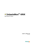
3.2 Project Timeline:
Research
Develop a
Configure
Configure
Attach light
Complete
technology
custom
system to act
sensor ports
and temp
electrical
for project
interface for
as a web
for periodic
sensors and
wiring for
processor
server
reading
connect
device
wiring
control
Summer ‘08
Fall ‘08
Week 1
Week 2
Week 3
Week 4
Week 5
Week 6
Week 7
Week 8
Week 9
Week 10
Winter
Break
Winter ‘09
Week 1
Week 2
Week 3
Week 4
Week 5
Week 6
Spring ‘09
Week 7
Week 8
Week 9
Week 10
Spring
Break
Figure 2: Project Development Timeline
14
4. Requirements
Primary: Requirements essential to the functioning of the system
Secondary: Requirements that may increase appeal, but are not necessary
Functional: Requirements describing what must be done
Non-Functional: Requirements describing the manner the functional requirement will be
achieved
4.1 Primary Requirements:
Functional:
-Monitors surroundings (using temperature)
-Acts as a web server
-Settings can be modified remotely
Non-Functional:
-System program is loaded on a microprocessor
-Monitors temperature using a temperature probe
-Modifies settings remotely using LWIP packets
4.2 Secondary Requirements:
Functional:
-Monitors various other aspects of environment
-Implements hysteresis for controlling heat and A/C together
-Allows users to monitor the system using an iPhone
Non-Functional:
-Connects various types of sensors to system
-Provides a threshold so neither A/C or heat are immediately activated
-Creates a user friendly and compact webpage which easily fits on iPhone screen
15
5.
Use
Cases
The use cases in this section describe the interaction between the user and the functional
elements of the system. The scope is the room monitoring system as a whole. The actor in the
following use cases is the user of the application, or anyone interested in monitoring their
surroundings remotely. The goals represent any action the user wishes to take using the
application, and each goal must be preceded by a precondition. In order for the goal to be
carried out, the user must follow the sequence of events for the particular use case. Most of the
following use cases pertain only to the monitoring and altering of the temperature using the
system.
5.1 Required
Scope: Room Monitoring System
Actor: User
Goal: Switch between devices
Precondition: Multiple devices have been attached and programmed into the system. Two or
more sensors have been connected to the input ports and the source code contains handlers for
these sensors.
Sequence of Events:
1) User turns system on
2) User arrives at home screen
3) User uses up-and-down arrows to switch between devices
Scope: Room Monitoring System
Actor: User
Goal: View Current temperature from device
Precondition: Temperature sensor has been connected to device.
Sequence of Events:
1) User turns system on
16
2) User arrives at home screen
3) User switches to temperature sensor and views temperature value on screen
Scope: Room Monitoring System
Actor: User
Goal: View Current temperature remotely
Precondition: Temperature sensor has been connected to device, user has access to the Internet,
and device has been switched on.
Sequence of Events:
1) User loads a browser and navigates to the web server’s home page
2) User views current value of temperature on web page
Scope: Room Monitoring System
Actor: User
Goal: Set Temperature from device
Precondition: Temperature sensor has been connected to device.
Sequence of Events:
1) User turns system on
2) User arrives at home screen
3) User switches to temperature sensor
4) User selects the menu option to change temperature and uses the up/down arrows to
change value
Scope: Room Monitoring System
Actor: User
Goal: Set temperature remotely
Precondition: Temperature sensor has been connected to device, user has access to the Internet,
and device has been switched on.
Sequence of Events:
1) User loads a browser and navigates to the web server’s home page
2) User selects new value of temperature using either the “+” or “-“ buttons
17
5.2 “Nice-to-Have”
Scope: Room Monitoring System
Actor: User
Goal: Change temperature from iPhone
Precondition: User has iPhone connected to the same network as device and remote system has
been switched on.
Sequence of Events:
1) User loads iPhone’s safari page and types in the system’s IP address
2) When connection to device is complete, user selects new temperature value using
either the “+” or “-“ buttons.
18
6. System Flowchart
Figure 3: System Flowchart
19
7. Technologies Used
Because this project uses an embedded system, both software and hardware technologies
were needed. The software technologies will be described, followed by the hardware
technologies used.
7.1 Software Technologies Used
IAR Systems Embedded Workbench:
IAR systems workbench is a compiler that works well with the LMS6965
microcontroller. I used this compiler for all of my programming, debugging, and loading of the
object code onto the controller. Furthermore, this compiler is nice because it allows for onboard
debugging, where I can use the actual controller in the debugging process.
C programming language:
The majority of the project’s source files are written in C. This language is appropriate
because the compiler allows for low-level function calls to be written in C (as opposed to
Assembly). Additionally, because this is an embedded system, timing can be rather important.
Using C is an efficient alternative to Java or any other high-level language.
JavaScript, HTML, CSS, and Ajax:
JavaScript is used for the web aspect of the project. When the microcontroller receives a
client request for the web page, it sends the JavaScript, HTML, CSS, etc. to the client that
displays the information and handles the user interaction respectively. The web site stores
information from the last page load including current temperature. The page also includes a few
buttons that will enable the user to change the temperature and send the new value back to the
server where the controller turns a fan or heater on or off based on the set temperature.
Furthermore, when the server connects to the device, it uses Ajax so the page does not have to
be refreshed.
Lightweight IP (LWIP):
20
LWIP is an Internet protocol, which was used to transport the data across the network
from the client to the server and visa versa. LWIP is a slimmed down version of TCP because
due to the limited memory of an embedded system, full TCP would not fit on the system’s
memory space.
Perl Scripting:
Perl was used as project maintenance rather than for the project itself. The IAR
workbench is able to load the compiled binaries onto the system. However, because the HTML
files are not compiled, a Perl script was run which converts the web files into binaries which can
then be loaded onto the system.
21
7.2 Hardware Technologies Used
Luminary Micro LMS6965 Microcontroller:
The LMS6965 microcontroller is the embedded device that will be running the source
code. This controller features a network link that can be connected to a local area network via
Ethernet. I used this feature for transferring data from the client to the web server and viceversa. The microcontroller also features an LCD, for enhancing the user interface and several
input ports for monitoring attached sensors.
LM-34 Temperature Probe:
This temperature probe, ordered from Parallax.com, is used to monitor the temperature.
The output voltage for this probe was connected to an Analog-to-Digital input port on the
controller where the user can monitor this value from the controller or a remote client.
Light Sensitive Resistor:
The light sensitive resistor, also ordered from Parallax.com, was hooked up to the
microcontroller in the same fashion the temperature probe was connected. The light sensitive
resistor yields a value of light intensity, which can be monitored either locally on the controller
or remotely.
Reed Relay Switches:
The Reed Relay switches were simply used to convert the 3V output from the
microcontroller into a 12V output powered by AA batteries. These switches allow real life
devices, such as lights, to be connected to the controller. Although the 12V output is not enough
to power actual heaters and air conditioners, it is enough to turn on a few lights to provide a
proof-of-concept demonstration.
Motion Sensor:
The motion sensor, also purchased from Parallax.com, was hooked up to the
microcontroller. Because the motion sensor outputs a value either 0 or 1 based on whether or
22
not the motion sensor was activated, a simple input port is used (rather than an analog-to-digital
converter) to monitor the motion sensor. The motion sensor is used to automatically turn the
light on or off.
Batteries, Wires, Resistors, and Breadboard:
Batteries, wires, resistors, and the breadboard were used to put the entire project together
and form the connections between the sensors, the controller, and the attached devices.
23
8. System Architecture
This system uses a two-tiered architecture. The microcontroller acts as the server, and
the user’s web browser acts as the client. There is no need for a data tier because most of the
data is dynamic (e.g. current temperature). However, for the little amount of data needed (such
as storing future set temperatures), arrays are enough. The arrays are allocated on the RAM of
the controller when the controller starts up.
Figure 4: System Architecture
24
9. Design Rationale
Considering that a functional requirement for this project was that it needed to allow the
user to use the system remotely, I decided to choose a networked microprocessor (the
LM3S6965 model) with a built-in Ethernet port. This microcontroller supported many inputs
and outputs, and it also had a few built-in analog-to-digital converters which were necessary for
the monitoring of the temperature and light sensors.
I chose to use the IAR systems compiler because it was highly compatible with the
system and made debugging and development a little simpler. In fact, the compiler had an onboard debugger, which allowed me to debug the software using the actual microcontroller rather
than a simulator.
JavaScript, HTML, and CSS were used for the web portion of the system because these
web languages are needed for handling user interactivity. The CSS was critical in making the
web site user friendly and compact, as the page would be displayed on both a computer’s web
browser as well as an iPhone’s web browser. The web page featured a tabbed design so that the
amount of space taken up by the page was minimized, thus being able to comfortably fit most of
the page (if not all) on smaller screens such as that of the iPhone.
Lastly, Ajax was used for the client-server interaction because a real-time system should
not need to be refreshed every time the user wishes to view an update of the temperature or
light. This results in a much more user friendly and straight-forward system. For instance, a
simple click changes the temperature on the actual controller as well as the web page without a
page reload.
25
10. Testing
This project was produced over a range of about thirty weeks from the end of Summer
’08 to the final product. Even though there was sufficient time to complete the product, testing
throughout the process was a critical aspect because embedded-system design can make
debugging difficult (especially when problems could be caused by either software bugs or
hardware failures). I tested my product using the following methods:
10.1 Unit Testing
I tested every individual component by creating simulated events. For example, to test to
make sure the LCD reports the correct temperature value without having to implement the
temperature sensor handler, I created a function that returns an arbitrary value, which is then
written to the LCD. By checking the LCD’s value against this value, I concluded that the LCD
was working properly. Similarly, I tested other aspects of the system such as the network
connection. To make sure the server knows how to handle client packets, I wrote a program to
send test packets to the IP address of the controller.
10.2 System Testing
After the unit testing was complete, I put all components together to see how they
synergize with one another. For example, the temperature sensor may return a proper voltage;
however, the function that checks this sensor may not convert the value properly. I also made
sure to combine dependent aspects of the project together and system test them before
combining all independent parts of the project for a complete comprehensive test.
26
11. Lessons Learned
After many months spent on the design and implementation of this project, there are a
few lessons that I have learned that may make my next experiences easier and smoother.
First, I will make sure to have extra sensors and other inexpensive hardware items on
hand as basic hardware components can simply stop working. On occasion, a broken
component slowed my project to a standstill. For example, if the motion sensor broke, the only
way to test whether or not my motion sensing software handler was working was to temporarily
change the code in order to simulate a motion detection. Since such components are so
inexpensive, it is reasonable to stock up on extra components.
Another lesson I learned was to determine the functionality that I would like my system
to support during the conception phase. Several times, I reworked my code to support a certain
feature because the original course of action would create a problem down the line. For
example, the web section underwent frequent changes as I could not decide on a set method to
send, receive, process, and display the data for the client. Eventually, I decided that Ajax would
be the best bet and a simple rectangular tabbed design box for user interactivity would ensure
that it could fit on the tiny iPhone screens.
27
12. Societal Issues
12.1 Ethical
Many products on the market have sparked ethical controversy due to a products’
material list, design, or purpose. This remote home monitoring system shall be subject to the
same ethical standards as any other product. However, I am confident that this system will not
generate major ethical controversies. No dangerous materials were used in the making of the
prototype and no dangerous materials shall be used in the making of the final product.
Similarly, this system does not invent any brand new technologies which may be subject
to controversies in the future. Rather, this product only combines current technologies – home
monitoring and network connections, to produce a seemingly ethically sound concept.
12.2 Social
I believe that this system will fully help the general public and lead to positive social
implications. It acts just like a current digital thermostat or other monitoring system. However,
this system is networked providing easy access to those in need. Disabled people for instance,
can access the remote system with ease and from anywhere in their house.
12.3 Political
I do not believe this system will have significant political considerations as it provides
benefits of personal safety, energy conservation and convenience. However, all of these are
politically important.
12.4 Economic
This monitoring system should save the customer money because it combines many
technologies into one. Many corporations may rely on many monitoring systems to effectively
monitor their surroundings, property, etc. However, this system uses the same networked
technology to deliver the current information from a multitude of attached sensors. Therefore,
many existing monitoring systems can effectively be replaced by one, thus saving the customer
money.
12.5 Health and Safety
As with any system that uses electricity, appropriate safeguards need to be taken in the
design and manufacture of the final product to ensure that it meets all appropriate product safety
standards. This would include for example, insuring that all of the electrical components are
28
contained within a plastic box, shielding the user of the product, as well as children and small
animals, from the danger of electric shock.
12.6 Manufacturability
This system does not have a resource-heavy design. In fact, the microcontroller was the
extent of the advanced technology used for this project. The actual designed system would not
use a microcontroller, but rather only the chip and the LCD. This would greatly minimize the
space taken up by the system thus decreasing the amount of materials and improving the
systems manufacturability.
12.7 Sustainability
This system is engineered to be sustainable in the narrow sense that it is designed to last
just as long as any current monitoring system, such as a thermostat. Its simple design provides
robustness and dependability.
This system also provides sustainability in the broad sense that it is built to be
upgradable and last even when other technologies change. The primary manner in which this
system accomplishes this task is due to the fact that the system is connected to a network at any
given time. Therefore, if the time comes that the system must be upgraded, it can simply
download new software from a content server via the Internet.
12.8 Environmental Impact
This system can have a positive impact to the environment. Because the system provides
convenience, it will encourage more people to turn their heat or A/C off whenever possible. For
example, many families may leave the heat on in their apartment or house while away for the
day so that the house is not too cold upon their return. However, if a customer is able to change
the temperature on the way home rather than leaving the temperature high the entire time, this
will save energy and help preserve the environment.
12.9 Usability
This system provides a simple and easy to use web interface. The interface to set the
temperature is similar to a digital thermostat. Next to a display of the desired temperature, there
are “-“ and “+” buttons to decrement or increment the temperature.
12.10 Lifelong learning
This project was an inspiration to lifelong learning in that it showed that new
technology, such as web interfaces and a microcontroller can be used to provide new solutions
for activities like setting the temperature on a thermostat.
29
12.11 Compassion
In addition to the convenience factor of being able to turn on lights and heating before
returning home, this system could also be used to provide disabled people, for instance, with
remote access for controlling temperature and lights with ease from anywhere in their house.
30
13. User Manual
13.1 Setting up the Room Monitoring System
First, before you apply power and connect Ethernet, make sure you find an appropriate
place for your system to reside. The light and motion sensors, located on the front of the box
cannot be blocked or they will not monitor the light intensity and motion properly. Similarly,
the box should not be placed next to sources of hot or cold air because it will affect the ability
for this system to monitor the temperature properly. You will also want to make sure you place
this system near a router or other connection to your network so you can easily connect it via
Ethernet. Once you have found a proper location for the system, you may move on to the next
step.
Second, apply power to the system by plugging the system into a nearby wall plug using
the included USB power adapter. When power is connected, an LED on the board will blink
several times and the LCD will read “Acquiring Address”. At this point, the system will attempt
to acquire an IP address. However, after forty seconds, it will timeout and return a default IP
address of “169.254.19.63” if the Ethernet has not been connected yet.
Third, to connect the Ethernet, plug any male Ethernet terminal into the Ethernet port on
the system with the other end of the Ethernet cable connected to your network (most typically
plugged directly into your router). If you have already provided power to the system and the
system has already returned its default IP address, then press the reset button (the button closest
to the top and closest to the right of the board). Pressing this button will tell the system to repeat
the IP address search process.
Note: The Room Monitoring System requires both a power and Ethernet connection in
order to monitor a surrounding remotely. If you would like to simply monitor the surrounding
locally, then an Ethernet connection is not needed.
31
13.2 Using the On-Board Interface
The system can monitor the surrounding locally using the on-board interface. The onboard interface, allows for a person to directly change settings on the controller. This is helpful
when the network connection is unavailable or not configured. The on-board interface allows
the user to switch between the attached devices (in this case a temperature and light controller
are attached).
The following flowcharts indicates how the user can navigate through the on-board
interface to access certain features:
Figure 5: Overall Project Flowchart
32
13.2 Using the On-Board Interface (Continued)
Figure 6: Detailed Project Flowchart – Main Options
33
13.2 Using the On-Board Interface (Continued)
Figure 7: Detailed Project Flowchart – Temperature Options
34
13.2 Using the On-Board Interface (Continued)
Figure 8: Detailed Project Flowchart – Light Options
35
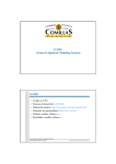
13.3 Using the Web Interface
The web interface allows most of the same changes to the device as the on-board
interface. The web interface uses a web client, assuming the device has an IP address. If the IP
address was assigned for use within a local area network (LAN) or any other type of private
network, then the controller may only be accessible within the LAN.
The interface allows most of the same changes to the device as the on-board interface.
The web interface uses a web client, assuming the device has an IP address. When the user
navigates to the page with the IP address assigned, the user will receive a page that resembles
the image below:
Figure 9: Web Interface Screen Shot
The tabs at the top of the webpage (see image above) indicate which devices are
attached and which device is currently selected. In this case, the two devices attached are
temperature and light and the currently selected device is the temperature tab. Each tab displays
information similar to what you may find on the on-board interface. Similarly, most of the
options from the on-board interface (such as “Set Temperature”) are easily accessible from the
36
web interface as well. Most of the options appear as buttons next to the information for which
they refer. The typical format for how the information and options will be displayed is as
follows. Each row represents a different type of information. In the first column of each row,
there will be a description of the data which exists in the second column. The third column, if
one exists, will contain the options for altering the data reading.
As an example, looking at the first column of the second row of the above image
indicates the data will be describing the “Desired Temperature”. The second column shows 80
degrees, representing the actual data and the third column provides the setting to alter the
temperature (a “-“ and “+” button to increment or decrement the temperature).
37
13.4 Using Temperature Monitoring Device
If monitoring locally, then switch to the temperature monitoring screen using the
directional buttons. This screen will show you the current temperature in the room and the
desired temperature in the room. It will also show you the “thermo” status, making this device
similar to a thermostat.
The current temperature reading displays the current temperature of the room in degrees
Fahrenheit. The desired temperature reading displays the temperature for which you prefer. The
thermo status reads either “Off”, “Heat”, or “Cool”. If the reading is “Off”, then both the heater
and air conditioner will be off. If the thermo status reads “Heat”, then the system will turn on
the heater until the current temperature reaches the desired temperature. If the thermo status
reads “Cool”, then the system will turn on the air conditioner until the current temperature
reaches the desired temperature. You can use the directional buttons to access the options to
change each setting (see flowcharts in section 12.2 for help understanding how to navigate
through the interface).
If monitoring remotely, then switch to the tab labeled “Temperature” on the system web
page. Simply click the buttons next to the corresponding field to either increment/decrement a
temperature value or toggle the thermo status (see section 12.3 for help using the web interface).
38
13.5 Using Light Monitoring Device
The light monitoring device operates similarly to the temperature device. If monitoring
the light locally, then switch to the light monitoring screen using the directional buttons. This
screen will show you the current light intensity in the room, whether or not motion detection is
enabled, and whether or not the light switch is on or off.
The light intensity will be between 0 and 5 with 0 being the dimmest and 5 being the
brightest. The motion status will read either “Off” or “On”. If off, then the light will not respond
to motion activity. If on, the light will turn on, if motion is detected, and it will stay on for as
long as the user specifies with the motion timeout option. The last piece of information
displayed is simply the light switch. If off, then the light is off (assuming that the light is not
turned on by another means such as motion detection). If the switch says on, then the light is
turned on.
If monitoring remotely, then switch to the tab labeled “Light” on the system web page.
Simply click the buttons next to the corresponding field to toggle various fields on or off such
as the light switch or motion detection.
39
14. Appendix:
14.1 Source Code – Web Technologies
/*************************************************
*
* File name: home.html
*
*************************************************/
<html>
<head>
<meta http-equiv="Content-Type" content="text/html;charset=ISO-8869-1">
<link href="./styles.css" rel="stylesheet" media="screen"></link>
<script type="text/javascript" src="tabber.js"></script>
<link rel="stylesheet" href="example.css" TYPE="text/css" MEDIA="screen">
<link rel="stylesheet" href="exampleprint.css" TYPE="text/css" MEDIA="print">
<title>Remote Monitoring System Homepage</title>
<style type="text/css">
.regular {
min-width:120px;
padding: 5px;
text-align:center;
border: none;
}
.switch {
min-width:120px;
padding: 5px;
text-align:center;
border: 0px solid black;
}
.embedded {
width:30px;
padding:0px;
text-align:center;
}
.tabbertabinvis {
display:none;
}
</style>
<script language="JavaScript">
var state = 1;
function datahandler(url)
{
var recv;
var req = false;
40
function dataComplete()
{
if(req.readyState == 4)
{
if(req.status == 200)
{
recv = req.responseText.split(";");
document.getElementById("tempCurrent").innerHTML = recv[0];
document.getElementById("tempSet").innerHTML = recv[1];
document.getElementById("statusSet").innerHTML = recv[2];
document.getElementById("statusLight").innerHTML = recv[5];
document.getElementById("motionTrigger").innerHTML = recv[6];
switch(recv[3]){
case "OFF ":
document.getElementById("heat").style.background = "red";
document.getElementById("cool").style.background = "red";
document.getElementById("heat").innerHTML = "OFF";
document.getElementById("cool").innerHTML = "OFF";
break;
case "HEAT":
document.getElementById("heat").style.background =
"#00FF00";
document.getElementById("cool").style.background = "red";
document.getElementById("heat").innerHTML = "ON";
document.getElementById("cool").innerHTML = "OFF";
break;
case "COOL":
document.getElementById("heat").style.background = "red";
document.getElementById("cool").style.background =
"#00FF00";
document.getElementById("heat").innerHTML = "OFF";
document.getElementById("cool").innerHTML = "ON";
break;
}
switch(recv[5]) {
case "OFF":
document.getElementById("statusLight").style.background =
"red";
break;
case "ON ":
document.getElementById("statusLight").style.background =
"#00FF00";
break;
}
if (recv[4] == 0) {
lightBar(0,0,0,0,0);
}
else if (recv[4] == 1) {
lightBar(1,0,0,0,0);
}
else if (recv[4] == 2) {
lightBar(1,1,0,0,0);
}
else if (recv[4] == 3) {
41
lightBar(1,1,1,0,0);
}
else if (recv[4] == 4) {
lightBar(1,1,1,1,0);
}
else if (recv[4] == 5) {
lightBar(1,1,1,1,1);
}
}
}
}
if(window.XMLHttpRequest)
{
req = new XMLHttpRequest();
}
else if(window.ActiveXObject)
{
req = new ActiveXObject("Microsoft.XMLHTTP");
}
if(req)
{
try {
req.open("GET", url + "?id=" + Math.random(), true);
req.onreadystatechange = dataComplete;
req.send(null);
}
catch (e) {
}
}
}
function temperatureUp()
{
datahandler("temperatureUp");
}
function temperatureDown()
{
datahandler("temperatureDown");
}
function tempStatusToggle()
{
datahandler("tempStatusToggle");
}
function lightStatusToggle()
{
datahandler("lightStatusToggle");
}
function motionStatusToggle()
{
datahandler("motionStatusToggle");
}
function autoRefreshToggle()
42
{
if (document.getElementById("refresh").innerHTML == "ON") {
document.getElementById("refresh").innerHTML = "OFF";
}
else {
document.getElementById("refresh").innerHTML = "ON";
}
}
function refreshLooper()
{
if (document.getElementById("refresh").innerHTML == "ON") {
datahandler("dataGet");
}
setTimeout('refreshLooper()',2000);
}
function loadFunc()
{
tabberAutomatic(tabberOptions);
refreshLooper();
}
function pausecomp(millis)
{
var date = new Date();
var curDate = null;
do { curDate = new Date(); }
while(curDate-date < millis);
}
function setLowLight() {
datahandler("lightSetLow");
}
function setHighLight() {
datahandler("lightSetHigh");
}
function lightBar(f1, f2, f3, f4, f5)
{
if (f1 > 0)
document.getElementById("light1").style.background = "blue";
else
document.getElementById("light1").style.background = "white";
if (f2 > 0)
document.getElementById("light2").style.background = "blue";
else
document.getElementById("light2").style.background = "white";
if (f3 > 0)
document.getElementById("light3").style.background = "blue";
else
document.getElementById("light3").style.background = "white";
if (f4 > 0)
43
document.getElementById("light4").style.background = "blue";
else
document.getElementById("light4").style.background = "white";
if (f5 > 0)
document.getElementById("light5").style.background = "blue";
else
document.getElementById("light5").style.background = "white";
}
document.write('<style type="text/css">.tabber{display:none;}<\/style>');
var tabberOptions = {
'manualStartup':true,
'onClick': function(argsObj) {
var
var
var
var
t = argsObj.tabber; /* Tabber object */
id = t.id; /* ID of the main tabber DIV */
i = argsObj.index; /* Which tab was clicked (0 is the first tab) */
e = argsObj.event; /* Event object */
if (i == 3) {
list = document.getElementById("Category2");
sublist = document.getElementById("SubCat2");
populateInfo(sublist);;
}
},
'addLinkId': true
};
</script>
</head>
<body onLoad="loadFunc();">
<div class="tabber" id="tab1" style="width:500px"><b>
<div class="tabbertab" title="Temperature" id="Temperature" tabbertabdefault>
<table border="2px" align="center">
<br><br>
<tr>
<td class="regular">Current Temperature:</td>
<td class="regular" id="tempCurrent">80</td>
</tr>
<tr>
<td class="regular">Desired Temperature:</td>
<td class="regular" id="tempSet">80</td>
<td class="regular">Set: <input type="button" id="down" value="
onClick="temperatureDown()">
<input type="button" id="up" value="
</tr>
<tr>
+
-
"
" onClick="temperatureUp()"></td>
44
<td class="regular">Status Switch:</td>
<td class="regular" id="statusSet">OFF</td>
<td class="regular"><input type="button" id="toggleTemp" value="Toggle"
onClick="tempStatusToggle()"></td>
</tr>
<tr>
<td class="regular">Heater:
<td class="regular" id="heat" bgcolor="red">OFF</td>
<tr>
<td class="regular">A/C:
<td class="regular" id="cool" bgcolor="red">OFF</td>
</tr>
</table>
<br><br>
</div>
<div class="tabbertab" title="Light" id="Light">
<br><br>
<table border="2px" align="center">
<td>
<table>
<tr>
<td class="regular">Current Light:</td>
<td class="regular" style="min-width:30px">L</td>
<td class="regular">
<table style="border: solid black">
<td class="embedded" id="light1"> </td>
<td class="embedded" id="light2"> </td>
<td class="embedded" id="light3"> </td>
<td class="embedded" id="light4"> </td>
<td class="embedded" id="light5"> </td>
</table>
</td>
<td class="regular" style="min-width:30px">H</td>
</tr>
</table>
<table>
<tr>
<td class="regular">Set low/high:</td>
<td class="regular"><input type="button" id="setLowButton" value="Set Low"
onClick="setLowLight()"></td>
<td class="regular"><input type="button" id="setHighButton" value="Set High"
onClick="setHighLight()"></td>
</tr>
<tr>
<td class="regular">Motion Detect:</td>
<td class="regular" id="motionTrigger">OFF</td>
<td class="regular "><input type="button" id="toggleMotion" value="Toggle"
onClick="motionStatusToggle()"></td>
</tr>
45
<tr>
<td class="regular">Light On/Off:</td>
<td class="regular" id="statusLight" bgcolor="red">OFF</td>
<td class="regular"><input type="button" id="toggleLight" value="Toggle"
onClick="lightStatusToggle()"></td>
</tr>
</table>
</td>
</table>
<br><br>
</div>
<div class="tabbertab" title="Settings" id="settings">
<table>
<tr>
<td class="regular">Auto Refresh: </td>
<td class="regular" id="refresh">ON</td>
<td><input type="button" id="refreshtoggle" value="Toggle"
onClick="autoRefreshToggle()">
</td>
</table>
</div>
</div></b>
</body>
</html>
46
/*************************************************
*
* File name: styles.css
*
*************************************************/
BODY
{
font-family: Arial;
background-color: white;
margin: 10px;
padding: 0px
}
BODY.side
{
font-family: Arial;
background-color: white;
margin: 10px;
padding: 0px
}
H1
{
background-color: white;
color: black;
font-weight: normal;
font-family: Arial;
font-size: 24pt;
text-decoration: none;
text-align: center;
}
47
14.2 Source Code – C files
/****************************************************************************
*
*
File name : clock.c
*
****************************************************************************/
// Include files
#include "clock.h"
#include "keystroke.h"
#include "graphics.h"
#include <stdio.h>
int gSECOND;
int gMINUTE;
int gHOUR;
int gDAY;
int gMONTH;
int gAMorPM;
char gAMPMarray[2];
unsigned int gYEAR;
char gPowerSaveTimer = 0;
char dateformat = 0;
// Lookup table holding the length of each mont. The first element is a
dummy.
int MonthLength[13] = {0, 31, 28, 31, 30, 31, 30, 31, 31, 30, 31, 30, 31};
int TBL_CLOCK_12[] =
// table used when displaying 12H clock
{12, 1, 2, 3, 4, 5, 6, 7, 8, 9, 10, 11, 12, 1, 2, 3, 4, 5, 6, 7, 8, 9, 10,
11};
/****************************************************************************
*
*
Function name: RTC_init
*
*
returns:
none
*
*
parameters:
none
*
*
Purpose:
Initialize the Real Time Clock
*
*
****************************************************************************/
void RTC_init(void)
{
// initial time and date setting
gSECOND = 0;
gMINUTE = 0;
gHOUR
= 12;
gDAY
= 1;
gMONTH
= 1;
gYEAR
= 3;
gAMorPM = 0;
48
gAMPMarray[0] = 'a';
gAMPMarray[1] = 'p';
}
/****************************************************************************
*
*
*
Function name : ShowClock
*
*
Returns :
void
*
*
Parameters :
char input (from joystick)
*
*
Purpose :
Shows the clock on the LCD
*
****************************************************************************/
void ShowClock (int vertical)
{
static int HH, HL, MH, ML, SH, SL;
char time[9];
HH = TBL_CLOCK_12[gHOUR];
if (HH > 9) {
HL = HH - 10;
HH = 1;
}
else {
HL = HH;
HH = 0;
}
MH = gMINUTE;
if (MH > 9) {
MH = MH / 10;
ML = gMINUTE - MH * 10;
}
else {
ML = MH;
MH = 0;
}
SH = gSECOND;
if (SH > 9) {
SH = SH / 10;
SL = gSECOND - SH * 10;
}
else {
SL = SH;
SH = 0;
}
sprintf
(time,"%d%d:%d%d:%d%d%cm\0",HH,HL,MH,ML,SH,SL,gAMPMarray[gAMorPM]);
displayText(time,35,vertical,15);
}
/****************************************************************************
49
*
*
*
Function name : SetClock
*
*
Returns :
void
*
*
Parameters :
char input (from joystick)
*
*
Purpose :
Adjusts the clock
*
*****************************************************************************
/
void SetClock(char input)
{
static int time[4];
// table holding the temporary clock setting
static char mode = HOUR;
static int HH, HL, MH, ML, SH, SL;
//initialize
time[HOUR] =
time[MINUTE]
time[SECOND]
time[AMPM] =
once
gHOUR;
= gMINUTE;
= gSECOND;
gAMorPM;
HH = TBL_CLOCK_12[time[HOUR]];
if (HH > 9) {
HL = HH - 10;
HH = 1;
}
else {
HL = HH;
HH = 0;
}
MH = time[MINUTE];
if (MH > 9) {
MH = MH / 10;
ML = time[MINUTE] - MH * 10;
}
else {
ML = MH;
MH = 0;
}
SH = time[SECOND];
if (SH > 9) {
SH = SH / 10;
SL = time[SECOND] - SH * 10;
}
else {
SL = SH;
SH = 0;
}
// Increment/decrement hours, minutes or seconds
if (input == UP)
time[mode]++;
else if (input == DOWN)
time[mode]--;
50
else if (input == LEFT)
{
if (mode == HOUR)
mode = AMPM;
else
mode--;
}
else if (input == RIGHT)
{
if (mode == AMPM)
mode = HOUR;
else
mode++;
}
else if (input == SELECT) {
mode = HOUR;
}
/* OPTIMIZE: Can
if (time[HOUR] >
time[HOUR] =
if (time[HOUR] <
time[HOUR] =
be solved by using a modulo operation */
12)
1;
1)
12;
if (time[MINUTE]
time[MINUTE]
if (time[MINUTE]
time[MINUTE]
>
=
<
=
59)
0;
0)
59;
if (time[SECOND]
time[SECOND]
if (time[SECOND]
time[SECOND]
>
=
<
=
59)
0;
0)
59;
gHOUR = time[HOUR];
gMINUTE = time[MINUTE];
gSECOND = time[SECOND];
if (time[AMPM] < 0) {
time[AMPM] = 1;
}
else if (time[AMPM] > 1) {
time[AMPM] = 0;
}
gAMorPM = time[AMPM];
return;
}
/****************************************************************************
*
*
*
Function name : ShowDate
*
*
Returns :
none
*
*
Parameters :
char input (from joystick)
*
*
Purpose :
Shows the date on the LCD
51
*
****************************************************************************/
void ShowDate(int vertical)
{
static char YH, YL, MH, ML, DH, DL;
char date[9];
YH = gYEAR;
if (YH > 9) {
YH = YH / 10;
YL = gYEAR - YH * 10;
}
else {
YL = YH;
YH = 0;
}
MH = gMONTH;
if (MH > 9) {
MH = MH / 10;
ML = gMONTH - MH * 10;
}
else {
ML = MH;
MH = 0;
}
DH = gDAY;
if (DH > 9) {
DH = DH / 10;
DL = gDAY - DH * 10;
}
else {
DL = DH;
DH = 0;
}
sprintf (date,"%d%d/%d%d/%d%d\0",MH,ML,DH,DL,YH,YL);
displayText(date,40,vertical,15);
}
#define YEAR
#define MONTH
#define DAY
0
1
2
/****************************************************************************
*
*
*
Function name: SetDate
*
*
Returns :
none
*
*
Parameters :
char input (from joystick)
*
*
Purpose :
Adjusts the date
*
****************************************************************************/
52
void SetDate(char input)
{
static char date[3];
// table holding the temporary date setting
static char mode = DAY;
static int YH, YL, MH, ML, DH, DL;
char MonthLength_temp;
char LeapMonth;
date[YEAR] = gYEAR;
date[MONTH] = gMONTH;
date[DAY] = gDAY;
if (mode == YEAR)
{
YH = date[YEAR];
if (YH > 9) {
YH = YH / 10;
YL = date[YEAR] - YH * 10;
}
else {
YL = YH;
YH = 0;
}
}
else if (mode == MONTH)
{
MH = date[MONTH];
if (MH > 9) {
MH = MH / 10;
ML = date[MONTH] - MH * 10;
}
else {
ML = MH;
MH = 0;
}
}
else if (mode == DAY)
{
DH = date[DAY];
if (DH > 9) {
DH = DH / 10;
DL = date[DAY] - DH * 10;
}
else {
DL = DH;
DH = 0;
}
}
// Increment/decrement years, months or days
if (input == UP)
date[mode]++;
else if (input == DOWN)
date[mode]--;
else if (input == LEFT)
{
if (mode == YEAR)
53
mode = DAY;
else
mode--;
}
else if (input == RIGHT)
{
if (mode == DAY)
mode = YEAR;
else
mode++;
}
else if (input == SELECT)
{
// store the temporary adjusted values to the global variables
mode = YEAR;
}
// OPTIMIZE: Can be solved by using a modulo operation
if (date[YEAR] == 255)
date[YEAR] = 99;
if (date[YEAR] > 99)
date[YEAR] = 0;
if (date[MONTH]
date[MONTH]
if (date[MONTH]
date[MONTH]
== 0)
= 12;
> 12)
= 1;
// Check for leap year, if month == February
if (gMONTH == 2)
if (!(gYEAR & 0x0003))
// if (gYEAR%4 == 0)
if (gYEAR%100 == 0)
if (gYEAR%400 == 0)
LeapMonth = 1;
else
LeapMonth = 0;
else
LeapMonth = 1;
else
LeapMonth = 0;
else
LeapMonth = 0;
if (LeapMonth)
MonthLength_temp = 29;
else
MonthLength_temp = MonthLength[date[MONTH]];
if (date[DAY]
date[DAY]
if (date[DAY]
date[DAY]
== 0)
= MonthLength_temp;
> MonthLength_temp)
= 1;
gYEAR = date[YEAR];
gMONTH = date[MONTH];
gDAY = date[DAY];
}
54
/****************************************************************************
*
*
*
Function name: IncrementSecond
*
*
Returns :
none
*
*
Parameters :
none
*
*
Purpose :
increments the time by one second and adjusts hours,
*
mins, days, years, etc. accordingly
*
****************************************************************************/
void IncrementSecond(void)
{
static char LeapMonth;
gSECOND++;
// increment second
if (gSECOND == 60)
{
gSECOND = 0;
gMINUTE++;
gPowerSaveTimer++;
if (gMINUTE > 59)
{
gMINUTE = 0;
gHOUR++;
if (gHOUR > 11)
{
if (gHOUR == 12) {
if (gAMorPM == AM) {
gAMorPM = PM;
}
else {
gAMorPM = AM;
gDAY++;
}
}
else {
gHOUR = 1;
}
// Check for leap year if month == February
if (gMONTH == 2)
if (!(gYEAR & 0x0003))
// if (gYEAR%4 == 0)
if (gYEAR%100 == 0)
if (gYEAR%400 == 0)
LeapMonth = 1;
else
LeapMonth = 0;
else
LeapMonth = 1;
else
55
LeapMonth = 0;
else
LeapMonth = 0;
// Now, we can check for month length
if (gDAY > (MonthLength[gMONTH] + LeapMonth))
{
gDAY = 1;
gMONTH++;
if (gMONTH > 12)
{
gMONTH = 1;
gYEAR++;
}
}
}
}
}
}
56
/****************************************************************************
*
*
File name : clock.h
*
****************************************************************************/
#define
#define
#define
#define
#define
#define
extern
extern
extern
extern
extern
extern
extern
extern
HOUR
MINUTE
SECOND
AMPM
AM
PM
0
1
2
3
0
1
int gSECOND;
int gMINUTE;
int gHOUR;
int gDAY;
int gMONTH;
unsigned int gYEAR;
int gAMorPM;
char gAMPMarray[2];
// Function declarations
void RTC_init(void);
//initialize the Timer Counter 2 in asynchron
operation
void Time_update(void);
//updates the time and date
void ShowClock(int vertical);
void SetClock(char input);
char SetClockFormat(char input);
void ShowDate(int vertical);
void SetDate(char input);
char SetDateFormat(char input);
void IncrementSecond(void);
57
/****************************************************************************
*
*
File name : get_ip.c
*
****************************************************************************/
#include
#include
#include
#include
#include
#include
#include
#include
#include
#include
#include
#include
"../../../hw_memmap.h"
"../../../hw_types.h"
"../../../src/uart.h"
"../rit128x96x4.h"
<stdio.h>
"enet.h"
"get_ip.h"
"globals.h"
"images.h"
"random.h"
"keystroke.h"
"graphics.h"
//***************************************************************************
//
// Draws a single number to the LCD
//
//***************************************************************************
static unsigned long
DrawNumber(unsigned long ulStart, unsigned long ulNumber, unsigned long
ulMask,
tBoolean bDot)
{
unsigned long ulLoop, ulIdx, ulDigit;
//
// Loop through the three possible digits in this number.
//
for(ulIdx = 1000000000; ulIdx > 0; ulIdx /= 10)
{
//
// Continue if this digit should not be drawn (i.e. the hundreds
digit
// for a two digit number).
//
if((ulNumber < ulIdx) && (ulIdx > ulMask))
{
continue;
}
//
// Extract this digit from the number.
//
ulDigit = (ulNumber / ulIdx) % 10;
//
// Loop over the bytes of the image for this digit.
//
for(ulLoop = 0; ulLoop < 52; ulLoop++)
{
//
58
// Copy this byte of the image to the local frame buffer.
//
g_pucFrame[ulStart + ((ulLoop / 4) * 64) + (ulLoop % 4)] =
g_ppucDigits[ulDigit][ulLoop];
}
//
// Skip past this digit in the local frame buffer.
//
ulStart += 4;
}
//
// See if a trailing dot should be drawn.
//
if(bDot)
{
//
// Loop over the bytes of the image for the dot.
//
for(ulLoop = 0; ulLoop < 26; ulLoop++)
{
//
// Copy this byte of the dot image to the local frame buffer.
//
g_pucFrame[ulStart + ((ulLoop / 2) * 64) + (ulLoop % 2)] =
g_pucDot[ulLoop];
}
//
// Skip past the dot in the local frame buffer.
//
ulStart += 2;
}
//
// Return the new frame buffer starting address so that further drawing
can
// occur after the number just drawn.
//
return(ulStart);
}
//***************************************************************************
//
// Get an IP address, store it in a global variable, display it on the LCD
//
//***************************************************************************
void GetIPAddress ()
{
unsigned long ulCount, ulLoop, ulAddr, ulStart, ulDigit;
ulAddr = 0;
int ip1,ip2,ip3,ip4;
char IPaddress[20];
int IPlength = 0;
while (ulAddr == 0) {
59
// Get the current IP address of the Ethernet interface.
This will
be
// zero when the IP address has not been assigned yet.
//
ulAddr = EnetGetIPAddr();
//
// See if the IP address has been assigned.
//
if(ulAddr == 0)
{
displayText("Acquiring Address",10,30,5);
displayText("Please Wait...",10,40,5);
}
else
{
//
// Get the width of the digits in the IP address.
//
ulDigit = ulAddr >> 24;
ulStart = (ulDigit > 99) ? 24 : ((ulDigit > 9) ? 16 : 8);
ulDigit = (ulAddr >> 16) & 0xff;
ulStart += (ulDigit > 99) ? 24 : ((ulDigit > 9) ? 16 : 8);
ulDigit = (ulAddr >> 8) & 0xff;
ulStart += (ulDigit > 99) ? 24 : ((ulDigit > 9) ? 16 : 8);
ulDigit = ulAddr & 0xff;
ulStart += (ulDigit > 99) ? 24 : ((ulDigit > 9) ? 16 : 8);
//
// Compute the starting address in the local frame buffer of the
// location for the "IP: <addr>" string.
//
ulStart = (81 * 64) + ((128 - (ulStart + 30)) / 4);
//
// Display the "IP:" text on the bottom of the display.
Loop
over
// the bytes in the image.
//
for(ulLoop = 0; ulLoop < (9 * 13); ulLoop++)
{
//
// Copy this byte from the image to the local frame buffer.
//
g_pucFrame[ulStart + ((ulLoop / 9) * 64) + (ulLoop % 9)] =
g_pucIP[ulLoop];
}
//
// Advance the frame buffer starting address.
//
ulStart += 9;
//
// Draw the first byte of the IP address, with a dot to separate
it
// from the next byte.
//
60
//ulStart = DrawNumber(ulStart, ulAddr & 0xff, 1, true);
ip1 = (int)(ulAddr & 0xff);
//
// Draw the second byte of the IP address, with a dot to separate
// it from the next byte.
//
//ulStart = DrawNumber(ulStart, (ulAddr >> 8) & 0xff, 1, true);
ip2 = (int)((ulAddr >> 8) & 0xff);
//
// Draw the third byte of the IP address, with a dot to separate
it
// from the next byte.
//
//ulStart = DrawNumber(ulStart, (ulAddr >> 16) & 0xff, 1, true);
ip3 = (int)((ulAddr >> 16) & 0xff);
//
// Draw the fourth bytes of the IP address.
//
//DrawNumber(ulStart, ulAddr >> 24, 1, false);
ip4 = (int)(ulAddr >> 24);
IPlength = sprintf(IPaddress,"IP:%d.%d.%d.%d\0",ip1,ip2,ip3,ip4);
IPlength = 18 - IPlength;
//RIT128x96x4Clear();
displayText(IPaddress,10+IPlength*3,85,15);
//
// Display the updated image on the display.
//
//RIT128x96x4ImageDraw(g_pucFrame, 0, 0, 128, 96);
}
}
}
61
/****************************************************************************
*
*
File name : get_ip.h
*
****************************************************************************/
// Function prototypes
extern void GetIPAddress(void);
#endif
62
/****************************************************************************
*
*
File name : globals.h
*
****************************************************************************/
#ifndef __GLOBALS_H__
#define __GLOBALS_H__
//***************************************************************************
//
// The clock rate for the SysTick interrupt. All events in the application
// occur at some fraction of this clock rate.
//
//***************************************************************************
#define CLOCK_RATE
300
//***************************************************************************
//
// A set of flags used to track the state of the application.
//
//***************************************************************************
extern unsigned long g_ulFlags;
#define FLAG_CLOCK_TICK
0
// A timer interrupt has occurred
#define FLAG_CLOCK_COUNT_LOW
1
// The low bit of the clock count
#define FLAG_CLOCK_COUNT_HIGH
2
// The high bit of the clock count
#define FLAG_UPDATE
3
// The display should be updated
#define FLAG_BUTTON
4
// Debounced state of the button
#define FLAG_DEBOUNCE_LOW
5
// Low bit of the debounce clock
#define FLAG_DEBOUNCE_HIGH
6
// High bit of the debounce clock
#define FLAG_BUTTON_PRESS
7
// The button was just pressed
#define FLAG_ENET_RXPKT
8
// An Ethernet Packet received
#define FLAG_ENET_TXPKT
9
// An Ethernet Packet transmitted
//***************************************************************************
//
// The speed of the processor.
//
//***************************************************************************
extern unsigned long g_ulSystemClock;
//***************************************************************************
//
// Storage for a local frame buffer.
//
//***************************************************************************
extern unsigned char g_pucFrame[6144];
//***************************************************************************
//
// The set of switches that are currently pressed.
//
//***************************************************************************
extern unsigned char g_ucSwitches;
#endif // __GLOBALS_H__
63
/****************************************************************************
*
*
File name : graphics.c
*
****************************************************************************/
#include "graphics.h"
//***************************************************************************
//
// Display text on the LCD display.
//
//***************************************************************************
int displayText(char pucHello[], int x, int y, int intensity)
{
RIT128x96x4StringDraw(&pucHello[0], x, y, 15);
return 1;
}
64
/****************************************************************************
*
*
File name : graphics.h
*
****************************************************************************/
#include
#include
#include
#include
#include
"../../../hw_types.h"
"../../../src/debug.h"
"../../../src/sysctl.h"
"../../../utils/diag.h"
"../rit128x96x4.h"
int displayText(char pucHello[], int x, int y, int intensity);
65
/****************************************************************************
*
*
File name : keystroke.c
*
****************************************************************************/
#include "keystroke.h"
static int gkeystroke;
int getKey() {
// See if only the up button is pressed.
if((g_ucSwitches & 0x0f) == 0x0e) {
return UP;
}
// See if only the down button is pressed.
if((g_ucSwitches & 0x0f) == 0x0d) {
return DOWN;
}
// See if only the left button is pressed.
if((g_ucSwitches & 0x0f) == 0x0b) {
return LEFT;
}
// See if only the right button is pressed.
if((g_ucSwitches & 0x0f) == 0x07) {
return RIGHT;
}
// See if only Select button was pressed
if(HWREGBITW(&g_ulFlags, FLAG_BUTTON_PRESS)) {
HWREGBITW(&g_ulFlags, FLAG_BUTTON_PRESS) = 0;
return SELECT;
}
return 0;
}
int getKeyWait() {
int key = 0;
int previous;
do {
previous = key;
key = getKey();
} while (key != 0);
return previous;
}
int lastKeyStroke() {
return gkeystroke;
}
void setLastKeyStroke(int key) {
gkeystroke = key;
}
66
/****************************************************************************
*
*
File name : keystroke.h
*
****************************************************************************/
#include
#include
#include
#include
#include
#include
#include
#include
#include
#include
#include
"../../../hw_memmap.h"
"../../../hw_types.h"
"../../../src/uart.h"
"../rit128x96x4.h"
"audio.h"
"enet.h"
"get_ip.h"
"globals.h"
"images.h"
"random.h"
"sounds.h"
// Define Key Strokes //
#define
#define
#define
#define
#define
#define
NONE 0
UP 1
DOWN 2
LEFT 3
RIGHT 4
SELECT 5
int getKey();
int getKeyWait();
int lastKeyStroke();
void setLastKeyStroke();
67
/****************************************************************************
*
*
File name : light.c
*
****************************************************************************/
#include
#include
#include
#include
#include
#include
int
int
int
int
int
"../../../hw_memmap.h"
"../../../hw_types.h"
"../../../src/gpio.h"
"../../../src/adc.h"
"light.h"
"motion.h"
currentLight = 0; //Light sensor scaled value
lightStatus = 0; //Light on or off
highLight = 500; //Intensity of light considered high
lowLight = 80;
//Intensity of light considered low
adcvalue = 0;
//Digital unscaled value of light sensor
//convert digital input into scaled value and store
void convertAndSetCurrentLight(int act) {
currentLight = 0;
adcvalue = act;
if (act >= (lowLight + ((highLight - lowLight)/5)
currentLight = 1;
if (act >= (lowLight + ((highLight - lowLight)/5)
currentLight = 2;
if (act >= (lowLight + ((highLight - lowLight)/5)
currentLight = 3;
if (act >= (lowLight + ((highLight - lowLight)/5)
currentLight = 4;
if (act >= highLight)
currentLight = 5;
}
to currentLight
* 0))
* 1))
* 2))
* 3))
//set the lowValue variable to the current light sensor value
void setLightLow() {
lowLight = adcvalue;
}
//set the highValue variable to the current light sensor value
void setLightHigh () {
highLight = adcvalue;
}
//returns the value stored in currentLight
int GetCurrentLight() {
return currentLight;
}
68
//returns the value stored in adcvalue
int GetADCLight() {
return adcvalue;
}
//run enableLight function to get current value of lightStatus
//and then return lightStatus
int GetLightStat() {
enableLight();
return lightStatus;
}
//toggle light on or off
void toggleLightSwitch() {
lightStatus = (lightStatus+1) % 2;
}
//check actual value of lightStatus and turn the actual light on or
//off depending on the value
void enableLight () {
if (lightStatus == 1 || (GetMotionSwitch() == ON && GetMotionStat() == ON))
{
GPIOPinWrite(GPIO_PORTD_BASE,GPIO_PIN_7,0);
}
else if ( lightStatus == 0 &&
( GetMotionSwitch() == OFF || (GetMotionSwitch() == ON &&
GetMotionStat() == OFF)) ) {
GPIOPinWrite(GPIO_PORTD_BASE,GPIO_PIN_7,GPIO_PIN_7);
}
}
69
/****************************************************************************
*
*
File name : light.h
*
****************************************************************************/
//This source file contains info for handling the light
#define TRUE 1
#define FALSE 0
#define OFF 0
#define ON 1
void convertAndSetCurrentLight(int act);
int GetCurrentLight();
void setLightLow();
void setLightHigh();
void enableLight();
int GetADCLight();
int GetLightStat();
void toggleLightSwitch();
70
/****************************************************************************
*
*
File name : main.c
*
****************************************************************************/
#include
#include
#include
#include
#include
#include
#include
#include
#include
#include
#include
#include
#include
#include
#include
#include
#include
#include
#include
#include
#include
#include
#include
#include
#include
#include
#include
#include
#include
#include
#include
"../../../hw_ints.h"
"../../../hw_memmap.h"
"../../../hw_sysctl.h"
"../../../hw_types.h"
"../../../src/adc.h"
"../../../src/debug.h"
"../../../src/gpio.h"
"../../../src/interrupt.h"
"../../../src/pwm.h"
"../../../src/sysctl.h"
"../../../src/systick.h"
"../../../src/timer.h"
"../../../src/uart.h"
"../rit128x96x4.h"
"audio.h"
"enet.h"
"get_ip.h"
"globals.h"
"images.h"
"random.h"
"screen_saver.h"
"sounds.h"
"graphics.h"
"keystroke.h"
"temperature.h"
"light.h"
"motion.h"
"clock.h"
<string.h>
<stdio.h>
<stdlib.h>
#define TRUE 1
#define FALSE 0
#define
#define
#define
#define
#define
#define
#define
#define
MAIN 0
TEMPERATURE 1
LIGHT 2
HUMIDITY 3
NUM_OF_DEVICES 3
HOME 0
MENU 1
OPTIONS 2
unsigned long g_ulFlags;
unsigned long g_ulSystemClock;
unsigned char g_pucFrame[6144];
static unsigned long g_ulTickCount = 0;
static unsigned char g_ucScreenUpdateCount = 0;
unsigned char g_ucSwitches = 0x1f;
static unsigned long g_ucSecondTick = 0;
71
static
static
static
static
static
static
static
static
static
static
unsigned char g_ucSwitchClockA = 0;
unsigned char g_ucSwitchClockB = 0;
unsigned long g_ucLCDOFFCount = 0;
unsigned long gMotionCount = 0;
int g_LCDOFF = FALSE;
int gCLOCK_SET = FALSE;
int gClearNeeded = FALSE;
int gselect = FALSE;
int gtimeout = 45;
int gettingIpAddress = FALSE;
void updateSensorData();
//***************************************************************************
//
// Handles the SysTick timeout interrupt.
//
//***************************************************************************
void
SysTickIntHandler(void)
{
unsigned long ulData, ulDelta;
//
// Increment the tick count.
//
g_ulTickCount++;
//
// Indicate that a timer interrupt has occurred.
//
HWREGBITW(&g_ulFlags, FLAG_CLOCK_TICK) = 1;
//
// Increment the screen update count.
//
g_ucScreenUpdateCount++;
g_ucSecondTick++;
//
// ONE SECOND HAS PASSED
//
if (g_ucSecondTick == CLOCK_RATE) {
/*
char timeout[12];
memset(timeout,'\0',sizeof(timeout));
if (gettingIpAddress == TRUE) {
gtimeout--;
sprintf(timeout,"Timeout: %d",gtimeout);
displayText("Timeout:
",30,60,5);
displayText(timeout,30,60,5);
}
*/
g_ucSecondTick = 0;
g_ucLCDOFFCount++;
if (getMotionPinRead() == TRUE) {
72
setMotionStat(TRUE);
gMotionCount = 0;
}
else if (gMotionCount >= getMotionTimeout()) {
setMotionStat(FALSE);
}
else {
gMotionCount++;
}
if (gCLOCK_SET == TRUE) {
IncrementSecond();
}
updateSensorData();
}
//
// See if 1/30th of a second has passed since the last screen update.
//
if(g_ucScreenUpdateCount == (CLOCK_RATE / 30))
{
//
// Restart the screen update count.
//
g_ucScreenUpdateCount = 0;
//
// Request a screen update.
//
HWREGBITW(&g_ulFlags, FLAG_UPDATE) = 1;
}
//
// Update the music/sound effects.
//
AudioHandler();
//
// Increment the application update count.
//
g_ucAppUpdateCount++;
//
// See if 1/100th of a second has passed since the last application
update.
//
if(g_ucAppUpdateCount != (CLOCK_RATE / 100))
{
//
// Return without doing any further processing.
//
return;
}
//
// Restart the application update count.
//
g_ucAppUpdateCount = 0;
73
//
// Run the Ethernet handler.
//
EnetTick(10);
//
// Read the state of the push buttons.
//
ulData = (GPIOPinRead(GPIO_PORTE_BASE, (GPIO_PIN_0 | GPIO_PIN_1 |
GPIO_PIN_2 | GPIO_PIN_3)) |
(GPIOPinRead(GPIO_PORTF_BASE, GPIO_PIN_1) << 3));
if (gClearNeeded == TRUE) {
gClearNeeded = FALSE;
}
if (ulData != 31) {
g_ucLCDOFFCount = 0;
if (g_LCDOFF == TRUE) {
RIT128x96x4DisplayOn();
gClearNeeded = TRUE;
g_LCDOFF = FALSE;
}
}
if (g_ucLCDOFFCount == 300 && g_LCDOFF == FALSE) {
g_LCDOFF = TRUE;
RIT128x96x4Clear();
RIT128x96x4DisplayOff();
}
//
// Determine the switches that are at a different state than the
debounced
// state.
//
ulDelta = ulData ^ g_ucSwitches;
//
// Increment the clocks by one.
//
g_ucSwitchClockA ^= g_ucSwitchClockB;
g_ucSwitchClockB = ~g_ucSwitchClockB;
//
// Reset the clocks corresponding to switches that have not changed
state.
//
g_ucSwitchClockA &= ulDelta;
g_ucSwitchClockB &= ulDelta;
//
// Get the new debounced switch state.
//
g_ucSwitches &= g_ucSwitchClockA | g_ucSwitchClockB;
g_ucSwitches |= (~(g_ucSwitchClockA | g_ucSwitchClockB)) & ulData;
//
// Determine the switches that just changed debounced state.
//
74
ulDelta ^= (g_ucSwitchClockA | g_ucSwitchClockB);
//
// See if any switches just changed debounced state.
//
if(ulDelta)
{
//
// Add the current tick count to the entropy pool.
//
RandomAddEntropy(g_ulTickCount);
}
//
// See if the select button was just pressed.
//
if((ulDelta & 0x10) && !(g_ucSwitches & 0x10))
{
//
// Set a flag to that the select button was just pressed.
//indicate
HWREGBITW(&g_ulFlags, FLAG_BUTTON_PRESS) = 1;
}
}
//Set the data according to the keystroke and show date on LCD
void mainSetDate() {
ShowDate(40);
SetDate(lastKeyStroke());
ShowDate(40);
}
//start the clock ticking
void mainStartTime() {
gCLOCK_SET = TRUE;
}
//stop the clock ticking
void mainStopTime() {
gCLOCK_SET = FALSE;
}
//Set the time according to the keystroke and show time on LCD
void mainSetTime() {
ShowClock(40);
SetClock(lastKeyStroke());
ShowClock(40);
}
//convert an int value (<1000) into a string
char* mainIntToStr(int value) {
static char string[4];
int tempvalue;
memset(string,'\0',sizeof(string));
if (value < 0) {
string[0] = '0';
return string;
}
75
else if (value < 10) {
string[0] = value+'0';
return string;
}
else if (value < 100) {
string[0] = ((int)(value/10))+'0';
string[1] = (value - (((int)(value/10))*10))+'0';
return string;
}
else if (value < 1000) {
string[0] = ((int)(value/100))+'0';
tempvalue = value - (int)(value/100)*100;
string[1] = ((int)(tempvalue/10))+'0';
string[2] = (tempvalue - (((int)(tempvalue/10))*10))+'0';
return string;
}
else {
string[0] = '9';
string[1] = '9';
string[2] = '9';
return string;
}
}
void mainShowTemp (int vertical) {
char temperatureStr[4];
int static previousTemp;
int static temperatureInt = 0;
displayText("Current Temp:",10,vertical,5);
previousTemp = temperatureInt;
temperatureInt = GetCurTemp();
strcpy(temperatureStr, mainIntToStr( temperatureInt ));
if (previousTemp != temperatureInt) {
displayText("
",85, vertical,5);
}
if (temperatureInt < 10) {
displayText(temperatureStr, 95, vertical,5);
}
else {
displayText(temperatureStr, 90, vertical,5);
}
displayText("F",110,vertical,5);
}
void mainShowSetTemp (int vertical) {
char temperatureStr[4];
int static previousTempSet;
int static temperatureIntSet = 0;
displayText("Desired Temp:",10,vertical,5);
previousTempSet = temperatureIntSet;
temperatureIntSet = GetSetTemp();
strcpy(temperatureStr, mainIntToStr( temperatureIntSet ));
if (previousTempSet != temperatureIntSet) {
displayText("
",85, vertical,5);
}
if (temperatureIntSet < 10) {
displayText(temperatureStr, 95, vertical,5);
}
76
else {
displayText(temperatureStr, 90, vertical,5);
}
displayText("F",110,vertical,5);
}
int mainAdjustTemp(int upOrDown, int temp) {
switch (upOrDown) {
case UP:
if (temp < 100)
temp = temp+5;
break;
case DOWN:
if (temp > 50)
temp = temp-5;
break;
}
return temp;
}
void mainSetCurrentTemp() {
char tempbuffer[5];
int sameValue;
memset(tempbuffer,0,sizeof(tempbuffer));
sameValue = GetSetTemp();
if (lastKeyStroke() != NONE) {
SetTemp(mainAdjustTemp(lastKeyStroke(),GetSetTemp ()));
}
strcpy(tempbuffer, mainIntToStr(GetSetTemp()));
if (sameValue != GetSetTemp()) {
displayText("
",45,45,5);
}
sprintf(tempbuffer,"%s F",tempbuffer);
displayText(tempbuffer,45,45,5);
}
void mainShowThermoStatus(int vertical) {
switch(GetThermStat()) {
case OFF:
displayText("Status: OFF
",25,vertical,5);
break;
case HEAT:
displayText("Status: HEAT
",25,vertical,5);
break;
case COOL:
displayText("Status: COOL
",25,vertical,5);
break;
}
}
void mainSetThermoStatus() {
mainShowThermoStatus(40);
switch (lastKeyStroke()) {
case LEFT:
toggleStatusDown();
break;
case RIGHT:
toggleStatusUp();
77
break;
}
mainShowThermoStatus(40);
}
void mainShowCurrentLight(int vertical) {
switch(GetCurrentLight()) {
case 0:
displayText("Light Intensity: 0/5",4,vertical,5);
break;
case 1:
displayText("Light Intensity: 1/5",4,vertical,5);
break;
case 2:
displayText("Light Intensity: 2/5",4,vertical,5);
break;
case 3:
displayText("Light Intensity: 3/5",4,vertical,5);
break;
case 4:
displayText("Light Intensity: 4/5",4,vertical,5);
break;
case 5:
displayText("Light Intensity: 5/5",4,vertical,5);
break;
}
}
void mainShowLightSwitch(int vertical) {
switch(GetLightStat()) {
case OFF:
displayText("Light Switch: OFF",20,vertical,5);
break;
case ON:
displayText("Light Switch: ON",20,vertical,5);
break;
}
}
void mainSetLightSwitch() {
mainShowLightSwitch(40);
switch (lastKeyStroke()) {
case LEFT:
toggleLightSwitch();
break;
case RIGHT:
toggleLightSwitch();
break;
}
mainShowLightSwitch(40);
}
void mainShowMotionSwitch(int vertical) {
switch(GetMotionSwitch()) {
case OFF:
displayText("Motion Enable: OFF",15,vertical,5);
break;
case ON:
78
displayText("Motion Enable:
break;
ON",15,vertical,5);
}
}
void mainSetMotionSwitch() {
mainShowMotionSwitch(40);
switch (lastKeyStroke()) {
case LEFT:
toggleMotionSwitch();
break;
case RIGHT:
toggleMotionSwitch();
break;
}
mainShowMotionSwitch(40);
}
void mainShowMotionTimeout(int vertical, int changed) {
char motionString[25];
memset(motionString,'\0',sizeof(motionString));
if (changed == TRUE) {
sprintf(motionString,"Motion Timeout:
");
displayText(motionString,15,vertical,5);
}
else {
sprintf(motionString,"Motion Timeout:
%s",mainIntToStr(getMotionTimeout()));
displayText(motionString,15,vertical,5);
}
}
void mainSetMotionTimeout() {
mainShowMotionTimeout(40, FALSE);
switch (lastKeyStroke()) {
case RIGHT:
if (getMotionTimeout() < 21) {
setMotionTimeout( getMotionTimeout() + 1 );
mainShowMotionTimeout(40, TRUE);
}
break;
case LEFT:
if (getMotionTimeout() > 1) {
setMotionTimeout( getMotionTimeout() - 1 );
mainShowMotionTimeout(40, TRUE);
}
break;
default:
mainShowMotionTimeout(40, FALSE);
break;
}
}
void blinkLED(int blinks) {
volatile unsigned long ulLoop;
int i;
for (i=0; i < blinks; i++)
{
79
//
// Turn on the LED.
//
GPIOPinWrite(GPIO_PORTF_BASE,GPIO_PIN_0,GPIO_PIN_0);
//
// Delay for a bit.
//
for(ulLoop = 0; ulLoop < 300000; ulLoop++)
{
}
//
// Turn off the LED.
//
GPIOPinWrite(GPIO_PORTF_BASE,GPIO_PIN_0,0);
//
// Delay for a bit.
//
for(ulLoop = 0; ulLoop < 300000; ulLoop++)
{
}
}
}
void updateSensorData () {
unsigned long tempStore1[8];
float ratio;
ADCSequenceDisable(ADC_BASE, 0);
ADCSequenceConfigure(ADC_BASE, 0, ADC_TRIGGER_PROCESSOR, 0);
ADCSequenceStepConfigure(ADC_BASE, 0, 0, ADC_CTL_CH0);
ADCSequenceStepConfigure(ADC_BASE, 0, 1, ADC_CTL_CH1 | ADC_CTL_IE |
ADC_CTL_END);
ADCIntEnable(ADC_BASE, 0);
ADCSequenceEnable(ADC_BASE, 0);
//
// Trigger the sample sequence.
//
ADCProcessorTrigger(ADC_BASE, 0);
//
// Wait until the sample sequence has completed.
//
while(!ADCIntStatus(ADC_BASE, 0, false))
{
}
ADCSequenceDataGet(ADC_BASE, 0, tempStore1);
ratio = (float)tempStore1[0]/1024.0;
ratio = ratio * 3.0;
ratio = ratio * 100;
setActualTemp( (int)ratio );
convertAndSetCurrentLight( (int) tempStore1[1] );
}
void showHome(int device) {
switch (device) {
case MAIN:
displayText("Main",53,15,5);
80
ShowClock(62);
ShowDate(40);
GetIPAddress();
break;
case TEMPERATURE:
displayText("Temperature",30,15,5);
mainShowTemp(40);
mainShowSetTemp(60);
mainShowThermoStatus(80);
break;
case LIGHT:
displayText("Light",50,15,5);
mainShowCurrentLight(40);
mainShowLightSwitch(60);
mainShowMotionSwitch(80);
break;
}
}
void showMenu(int device, int option) {
displayText("Options",40,15,5);
switch (device) {
case MAIN:
switch(option) {
case 0:
displayText("Set Time",37,40,5);
break;
case 1:
displayText("Set Date",37,40,5);
break;
}
break;
case TEMPERATURE:
switch(option) {
case 0:
displayText("Set Temperature",23,40,5);
break;
case 1:
displayText("Set Thermo Status",20,40,5);
break;
}
break;
case LIGHT:
switch(option) {
case 0:
displayText("Switch Light On/Off",10,40,5);
break;
case 1:
displayText("Switch Motion On/Off",10,40,5);
break;
case 2:
displayText("Set Motion Timeout",10,40,5);
break;
}
break;
}
}
81
void showOptions (int device, int option) {
switch (device) {
case MAIN:
switch(option) {
case 0:
displayText("Set Time",37,15,5);
mainSetTime();
break;
case 1:
displayText("Set Date",37,15,5);
mainSetDate();
break;
}
break;
case TEMPERATURE:
switch(option) {
case 0:
displayText("Set Temperature",23,15,5);
mainSetCurrentTemp();
break;
case 1:
displayText("Set Thermo Status",20,15,5);
mainSetThermoStatus();
break;
}
break;
case LIGHT:
switch(option) {
case 0:
displayText("Switch Light On/Off",10,15,5);
mainSetLightSwitch();
break;
case 1:
displayText("Switch Motion On/Off",2,15,5);
mainSetMotionSwitch();
break;
case 2:
displayText("Set Motion Timeout",10,15,5);
mainSetMotionTimeout();
break;
}
break;
}
}
// Main Function
int
main(void)
{
int keystroke;
int device = MAIN;
int state = HOME;
int option = 0;
int numOptions = 0;
int clear;
//
// If running on Rev A2 silicon, turn the LDO voltage up to 2.75V.
This
82
is
// a workaround to allow the PLL to operate reliably.
//
SysCtlPeripheralEnable(SYSCTL_PERIPH_ADC);
if(REVISION_IS_A2)
{
SysCtlLDOSet(SYSCTL_LDO_2_75V);
}
//
// Set the clocking to run at 50MHz from the PLL.
//
SysCtlClockSet(SYSCTL_SYSDIV_4 | SYSCTL_USE_PLL | SYSCTL_OSC_MAIN |
SYSCTL_XTAL_8MHZ);
SysCtlPWMClockSet(SYSCTL_PWMDIV_8);
//
// Get the system clock speed.
//
g_ulSystemClock = SysCtlClockGet();
//
// Enable the peripherals used by the application.
//
SysCtlPeripheralEnable(SYSCTL_PERIPH_GPIOA);
SysCtlPeripheralEnable(SYSCTL_PERIPH_GPIOB);
SysCtlPeripheralEnable(SYSCTL_PERIPH_GPIOC);
SysCtlPeripheralEnable(SYSCTL_PERIPH_GPIOD);
SysCtlPeripheralEnable(SYSCTL_PERIPH_GPIOE);
SysCtlPeripheralEnable(SYSCTL_PERIPH_GPIOF);
SysCtlPeripheralEnable(SYSCTL_PERIPH_PWM);
SysCtlPeripheralEnable(SYSCTL_PERIPH_UART0);
GPIOPinTypeGPIOOutput(GPIO_PORTD_BASE, GPIO_PIN_4 | GPIO_PIN_5 |
GPIO_PIN_7);
GPIOPinWrite(GPIO_PORTD_BASE,GPIO_PIN_4,GPIO_PIN_4);
GPIOPinWrite(GPIO_PORTD_BASE,GPIO_PIN_5,GPIO_PIN_5);
GPIOPinWrite(GPIO_PORTD_BASE,GPIO_PIN_7,GPIO_PIN_7);
GPIOPinTypeGPIOInput(GPIO_PORTD_BASE, GPIO_PIN_2);
//
// Configure the GPIOs used to read the state of the on-board push
buttons.
//
GPIOPinTypeGPIOInput(GPIO_PORTE_BASE,
GPIO_PIN_0 | GPIO_PIN_1 | GPIO_PIN_2 | GPIO_PIN_3);
GPIOPadConfigSet(GPIO_PORTE_BASE,
GPIO_PIN_0 | GPIO_PIN_1 | GPIO_PIN_2 | GPIO_PIN_3,
GPIO_STRENGTH_2MA, GPIO_PIN_TYPE_STD_WPU);
GPIOPinTypeGPIOInput(GPIO_PORTF_BASE, GPIO_PIN_1);
GPIOPadConfigSet(GPIO_PORTF_BASE, GPIO_PIN_1, GPIO_STRENGTH_2MA,
GPIO_PIN_TYPE_STD_WPU);
//
// Configure the LED, speaker, and UART GPIOs as required.
//
83
GPIOPinTypeUART(GPIO_PORTA_BASE, GPIO_PIN_0 | GPIO_PIN_1);
GPIOPinTypePWM(GPIO_PORTD_BASE, GPIO_PIN_1);
GPIOPinTypeGPIOOutput(GPIO_PORTF_BASE, GPIO_PIN_0);
GPIOPinWrite(GPIO_PORTF_BASE, GPIO_PIN_0, 0);
//
// Intialize the Ethernet Controller and TCP/IP Stack.
//
EnetInit();
//
// Configure the first UART for 115,200, 8-N-1 operation.
//
UARTConfigSetExpClk(UART0_BASE, SysCtlClockGet(), 115200,
(UART_CONFIG_WLEN_8 | UART_CONFIG_STOP_ONE |
UART_CONFIG_PAR_NONE));
UARTEnable(UART0_BASE);
//
// Send a welcome message to the UART.
//
UARTCharPut(UART0_BASE, 'W');
UARTCharPut(UART0_BASE, 'e');
UARTCharPut(UART0_BASE, 'l');
UARTCharPut(UART0_BASE, 'c');
UARTCharPut(UART0_BASE, 'o');
UARTCharPut(UART0_BASE, 'm');
UARTCharPut(UART0_BASE, 'e');
UARTCharPut(UART0_BASE, '\r');
UARTCharPut(UART0_BASE, '\n');
//
// Initialize the OSRAM OLED display.
//
RIT128x96x4Init(3500000);
//
// Initialize the PWM for generating music and sound effects.
//
AudioOn();
//
// Configure SysTick to periodically interrupt.
//
SysTickPeriodSet(g_ulSystemClock / CLOCK_RATE);
SysTickIntEnable();
SysTickEnable();
//
// Throw away any button presses that may have occurred while the splash
// screens were being displayed.
//
HWREGBITW(&g_ulFlags, FLAG_BUTTON_PRESS) = 0;
RTC_init();
blinkLED(10);
gettingIpAddress = TRUE;
GetIPAddress();
gettingIpAddress = FALSE;
84
blinkLED(10);
RIT128x96x4Clear(); //clear LCD
mainStartTime();
while (1) {
if (gselect == TRUE) {
keystroke = SELECT;
gselect = FALSE;
}
else {
keystroke = getKeyWait();
}
enableHeatCool();
enableLight();
clear = TRUE;
switch (state) {
case HOME:
if (keystroke == RIGHT)
device = (device+1) % NUM_OF_DEVICES;
else if (keystroke == LEFT) {
device = device-1;
if (device == -1) {
device = NUM_OF_DEVICES-1;
}
}
else if (keystroke == UP)
state = MENU;
else
clear = FALSE;
break;
case MENU:
if (keystroke == RIGHT)
option = (option+1) % numOptions;
else if (keystroke == LEFT) {
option = option-1;
if (option == -1) {
option = numOptions-1;
}
}
else if (keystroke == DOWN)
state = HOME;
else if (keystroke == UP)
state = OPTIONS;
else if (keystroke == SELECT)
state = HOME;
else
clear = FALSE;
break;
case OPTIONS:
if (keystroke == SELECT)
state = MENU;
if (keystroke != SELECT) {
clear = FALSE;
setLastKeyStroke(keystroke);
}
break;
}
if (clear == TRUE)
85
RIT128x96x4Clear();
switch(state) {
case HOME:
showHome(device);
break;
case MENU:
switch (device) {
case MAIN: numOptions = 2; break;
case TEMPERATURE: numOptions = 2; break;
case LIGHT: numOptions = 3; break;
}
showMenu(device,option);
break;
case OPTIONS:
showOptions(device,option);
break;
}
}
}
86
/****************************************************************************
*
*
File name : motion.c
*
****************************************************************************/
#include
#include
#include
#include
"../../../hw_memmap.h"
"../../../hw_types.h"
"../../../src/gpio.h"
"motion.h"
int motionStat = 0;
//Motion detected - yes or no (1 or 0)
int motionSwitch = 0; //Motion switch - on or off (1 or 0)
int motionTimeout = 5;
//read whether or not motion sensor has detected movement
int getMotionPinRead() {
if ( GPIOPinRead(GPIO_PORTD_BASE, GPIO_PIN_2) == GPIO_PIN_2 ) {
return 1;
}
return 0;
}
//sets the value for motionStat
void setMotionStat(int motionBool) {
motionStat = motionBool;
}
//returns current value stored in motionStat
int GetMotionStat() {
return motionStat;
}
//returns whether or not light is set to respond to motion
int GetMotionSwitch() {
return motionSwitch;
}
//toggle motion detector setting on or off
void toggleMotionSwitch() {
motionSwitch = (motionSwitch+1) % 2;
}
int getMotionTimeout() {
return (motionTimeout);
}
void setMotionTimeout(int timeout) {
motionTimeout = timeout;
}
87
/****************************************************************************
*
*
File name : motion.h
*
****************************************************************************/
#define TRUE 1
#define FALSE 0
int getMotionPinRead();
void setMotionStat(int motionBool);
int GetMotionStat();
int GetMotionSwitch();
void toggleMotionSwitch();
int getMotionTimeout();
void setMotionTimeout(int timeout);
88
/****************************************************************************
*
*
File name : temperature.c
*
****************************************************************************/
#include
#include
#include
#include
#include
int
int
int
int
"../../../hw_memmap.h"
"../../../hw_types.h"
"../../../src/gpio.h"
"../../../src/adc.h"
"temperature.h"
tempValue = 80;
actualTemp = 0;
thermoStatus = 0;
heatOrCool = 0;
//Temperature to turn on AC (degrees F)
//Current temperature in room (degrees F)
//Status of thermostat (OFF, HEAT, COOL)
//1 = heater on, 2 = A/C on, 0 = both off
//return value stored in tempValue
int GetSetTemp () {
return tempValue;
}
//set actual temperature value using input (from sensor call)
void setActualTemp(int act) {
actualTemp = act;
}
//Set desired temperature according to parameter temperature
void SetTemp (int newTemp) {
if (newTemp < 50) {
tempValue = 50;
}
else if (newTemp > 100) {
tempValue = 100;
}
else {
tempValue = newTemp;
}
}
//return current temperature in room
int GetCurTemp() {
return actualTemp;
}
//return thermostat status
int GetThermStat() {
return thermoStatus;
}
//toggle thermoStatus in the upward direction
void toggleStatusUp() {
thermoStatus = (thermoStatus+1) % 3;
}
//toggle thermoStatus in the downward direction
void toggleStatusDown() {
thermoStatus = thermoStatus-1;
89
if (thermoStatus == -1) {
thermoStatus = 2;
}
}
//run enableHeatCool function to get current value of heatOrCool
//and then return heatOrCool
int GetEnabled() {
enableHeatCool();
return heatOrCool;
}
//compare current temperature with desired temperature and check
//thermoStatus to determine whether heater or AC should be on.
//Then turn either on or off according to those conditions.
void enableHeatCool () {
if (thermoStatus == HEAT) {
if (GetSetTemp() > GetCurTemp()) {
heatOrCool = 1;
GPIOPinWrite(GPIO_PORTD_BASE,GPIO_PIN_4,0);
GPIOPinWrite(GPIO_PORTD_BASE,GPIO_PIN_5,GPIO_PIN_5);
}
else if (GetCurTemp() - GetSetTemp() > TEMPDELTA) {
heatOrCool = 0;
GPIOPinWrite(GPIO_PORTD_BASE,GPIO_PIN_4,GPIO_PIN_4);
GPIOPinWrite(GPIO_PORTD_BASE,GPIO_PIN_5,GPIO_PIN_5);
}
}
else if (thermoStatus == COOL) {
if (GetSetTemp() < GetCurTemp()) {
heatOrCool = 2;
GPIOPinWrite(GPIO_PORTD_BASE,GPIO_PIN_5,0);
GPIOPinWrite(GPIO_PORTD_BASE,GPIO_PIN_4,GPIO_PIN_4);
}
else if (GetSetTemp() - GetCurTemp() > TEMPDELTA) {
heatOrCool = 0;
GPIOPinWrite(GPIO_PORTD_BASE,GPIO_PIN_4,GPIO_PIN_4);
GPIOPinWrite(GPIO_PORTD_BASE,GPIO_PIN_5,GPIO_PIN_5);
}
}
else {
heatOrCool = 0;
GPIOPinWrite(GPIO_PORTD_BASE,GPIO_PIN_4,GPIO_PIN_4);
GPIOPinWrite(GPIO_PORTD_BASE,GPIO_PIN_5,GPIO_PIN_5);
}
}
90
/****************************************************************************
*
*
File name : temperature.h
*
****************************************************************************/
//Temperature.h
//This source file contains info for handling the temperature
#define TRUE 1
#define FALSE 0
#define OFF 0
#define HEAT 1
#define COOL 2
#define TEMPDELTA 2
int GetSetTemp();
void SetTemp (int newTemp);
int GetCurTemp();
int GetEnabled();
void toggleStatusUp();
void toggleStatusDown();
int GetThermStat();
void enableHeatCool();
void setActualTemp();
91