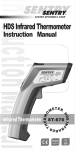
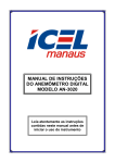
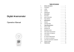
1
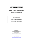
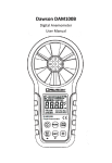
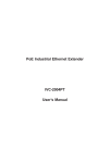
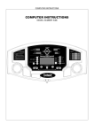
IRthermo-Anemometer with built-in Infrared Thermometer Model-ST732 Instruction Manual IRthermo-Anemometer with built-in Infrared Thermometer RoHS Ver.01 10/ Aug. COMPLIANT 1. Product Introduction ---------------------- 1 1-1 Features ----------------------------------- 1 1-2 Applications ------------------------------- 2 2. Safety Information -------------------------- 2 2-1 Cautions ------------------------------------ 2 2-2 Safety Symbols ---------------------------- 2 3. Specifications ------------------------------- 4 3-1 General Specification -------------------- 4 3 -2 Technical Specification ------------------ 5 6 4. General Descriptions -----------------4-1 Unit Diagram ------------------------------ 7 4-2 LCD Panel --------------------------------- 7 4-3 Battery Placement ----------------------- 8 4-4 AC Power -------------------------------- 8 4-5 Sensor Tip Description -------------------10 5. Mode Functions ---------------------------- 11 5-1 Air Velocity / Air Temperature Measurement ------------------------------12 5-2 Air Flow Measurement -------------------12 5-3 IR Thermometer Measurement----------12 5-4 Maximum/Minimum/Average Measurement- ----------------------------- 13 5-5 Data Logger & Data Record / Recall----13 6. Advanced Set Functions ------------------14 6-1 Air Velocity Setting -----------------------15 6-2 Air Flow Setting ---------------------------15 6-3 IR Thermometer Setting ----------------- 15 6-4 Sample Time of Data Log Setting ------ 15 6-5 Clear Memory ---------------------------- 15 6-6 Data / Time Setting ----------------------16 6-7 Laser and Backlight ON/OFF - ----------16 7. Communication ------------------------------16 8. Techniques ------------------------------------16 8-1 Useful Equations ------------------------- 16 8-2 Field Of View (FOV) And D istance & Spot Size (DS) Ratio ---------------------17 8-3 Emissivity ---------------------------------17 9. Maintenance --------------------------------- 18 1. Product Introduction Thank you for purchasing this IRthermo-Anemometer with built-in non-contact Infrared Thermometer. The IRthermo-Anemometer is an air velocity, air flow (volume), temperature of air, and non-contact infrared temperature measuring instrument. To measure an air velocity, put the sensor head face to the measurement air. Then the first reading will show the air velocity value. To measure a temperature, point the meter at a target until the temperature is read. (Make sure the target area is larger than the unit's spot size. For large target objects assure you are within target distance.) 1-1 Features • Simultaneous display of air flow in CFM / CMM or air velocity plus ambient temperatures. • Combination of hot wire and standard thermister , deliver rapid and precise measurements event at low air velocity. • Wide range measurement of air velocity, fast response time. • Multi-functions for air velocity measurement: m/s, km/h,ft/min, knots, mile/h. • Infrared thermometer measures remote surface temperature to 932˚F(500˚C) with 8:1 distance to spot ratio and laser pointer • Super large LCD with dual function display, read the air velocity & temperature at the same time. • Real time data logger, build in clock (hour-min.-sec. , year-month-date). • Data hold and record / recall maximum,minimum and average reading. • Ultra low power consumption in shutdown mode. • Auto power off after 10 minutes of idle (30 Minutes with AC Power) • USB PC interface. 1 1-2 Applications • Air conditioner • Refrigerated case • Ventilation system • Furnace flow velocity • Fans / motors / blowers • Environmental testing • Long distance temperature monitoring • Manufacturing processes of semiconductor technology 2. Safety Information Read the following safety information carefully before attempting to operate or service the meter. Only qualified personnel should perform repairs or servicing not covered in this manual. Laser Warning Note! Do not point laser directly at eye. Use caution a round reflective surfaces. Keep out of reach of children. 2-1 Cautions! • DO NOT submerge the unit in water. • This product is not designed for use in medical evaluations. The product can only be used to measure body temperature simply for reference. They are meant for industrial and scientific purposes. 2-2 Safety symbols Dangerous, refer to this manual before using the meter. CE Certification This instrument conforms to the following standards: EN61326: Electrical equipment for measurement, control and laboratory use. IEC61000-4-2: Electrostatic discharge immunity test. IEC61000-4-3: Radiated, radio-frequency, electromagnetic field immunity test. IEC61000-4-8: Power frequency magnetic field immunity test. IEC60825-1: Safety. 2 Restrict to use of six substances within electrical and electronic equipment (EEE), thereby contributing to the protection of human health and the environment. The device may not be disposed of with the trash. It promotes the re-use recycling and other forms of recovery of used materials and components, and to improve the environmental performance of all operators (manufacturers, traders and treatment facilities) involved in the life cycle of products. Dispose of the product appropriately in accordance with the regulations in force in your country REACH (SVHC) The device of used materials content no following substances that list of proposed REACH substances of very highconcern . 3 3. Specification 3-1 General Specification Measurement Air Velocity:m/s, ft/min, km/h, mile/h ,knots Air Flow:CMM(m³/min), CFM(ft³/min) Temperature:°C and °F Sensors Air Velocity / Air Flow Sensor :Hot wire Infrared sensor :Thermopile Operating Temp. Storage Temp. 0~50 ° C (32~122 °F ),10~90%RH -10~60 ° C ( 14~140 °F ) Sample Time Approx. 0.5 sec. Data Logging YES (20000 points) Record Function YES (9 points) Time Interval YES PC Interface YES AC Power YES Multi-LCD Display YES Max / Min / Avg YES LCD Backlight YES Data Hold YES Weight Approx. 320g (11.3 oz.) Auto Power Off 10 Minutes of idle (30 Minutes with AC Power) Dimensions Accessories 184×70×40mm (7.24"×2.75"×1.57") Telescope probe: approx. 1800mm (70.8inch)include wire rod. 9V Battery, Instruction manual, Carrying case, AC Input, USB Transmission line, PC Interface window-bace software. 4 3-2 Technical Specification Air Velocity: 0~40m/s, 0~7874ft/min, 0~144km/h, 0~89.5mile/h, 0~77.75knots Air Flow: 0~72,000 CMM (m³/min), Range 0~2,542,700 CFM (ft³/min) Air Flow(Area):0.001~30m², 0.01~322.92ft² Air Temperature: 0~70°C(32~158°F) Temperature:-32~537.5°C(-25~999°F) Resolution Accuracy (%reading) Emissivity Air Velocity: 0.01m/s, 0.1ft/min, 0.01km/h, 0.01mile/h, 0.01knots Air Flow:1CMM ; 1CFM (0~99999 CFM), 10CFM (100000~999990 CFM), 100CFM (1000000~1907000 CFM), Air Flow(Area):0.001m²(0.01ft²) Air Temperature:0.1°C(0.1°F) Temperature:0.1°C(0.1°F) Air Velocity:±(0.03+3%)m/s, ±(5.9+3%)ft/min , ±(0.11+3%)km/h,±(0.07+3%)mile/h, ±(0.06+3%)knots Air Flow: 1.8 m³/min + ±3% of reading Temperature:±3.0°C(±5.4°F) from -32~-20°C(-25~-4°F), ±2.0°C(±3.6°F) from -20~100°C(-4~212°F), ±2% from 100~537.5°C(212~999°F) 0.95 fixed Distance/Spot Ratio 8:1 5 4. General Descriptions 4-1 Unit Diagram 1 14 2 15 3 4 8 9 5 6 10 7 11 13 12 1 Power Button 9 2 LCD Screen 10 ▲ U p B u t t o n 3 REC( 11 P r o b e S o c k e t ) Button MODE(SET) Button 4 IR Thermometer Hold Button 12 M e a s u r i n g W i n d o w 5 ▼ Down Button 13 L a s e r S i g h t i n g 6 Anemometer Hold Button 14 S e n s o r H e a d 7 AC Input Terminal 15 P r o b e P l u g 8 Laser / Backlight Button 6 4-2 LCD Panel I A J B C D K h-m-s y-m-d Memory Space CLR-Memory X10 X100 L M E mile/h F G H MAX MIN AVG DATA RECALL LOG LINK EMS N O A Time Interval /Laser / Backlight I IR Thermometer Hold J Low Battery B Secondary Reading K C Memory Space / Clear Memory IR Thermometer Unit L Ti m e / D a t e D X10 / X100 M Anemometer Hold E Primary Reading N Anemometer Unit F MAX / MIN / AVG O Te r t i a r y R e a d i n g G DATA Record / Recall / Log H PC Link / EMS 7 4-3 Battery Change The meter is powered by a 9V battery. When symbol appear, the battery voltage drops below the level for reliable operation, the user has to replace a new battery . To change the battery, open the battery cover on the back and replace the battery in the battery compartment. Make sure the cover is well snapped after the replacement of battery. Tilt stand 4-4 AC Power Except battery power supply, the unit also consumes AC power via USB cable: a. Plug “A” male of the cable into “A” receptacle of the AC adapter included in the package(Fig. 1)and plug mini “B” male into the mini “B” receptacle of the unit. b. Plug the AC adapter to the wall jack (Fig. 2)Option. c. Plug “A” male into PC or Notebook USB port(Fig. 3). • AC Plug with interchangeable PIN (Please see specification ) A B 8 9 4-5 Sensor Tip Description • Sensor Head: Not in Use Measurement 1 2 3 1 Air Direction Arrow To protect the sensors, please telescope the sensor head into the wand when the meter is not in use. Air Velocity Sensor (Do not touch !) 3 Temperature Sensor 2 Warning! Do not touch the air velocity or temperature thermistor inside the sensor head. Air Velocity Measurement: Place the sensor in the air current to be measured. Have the air flow meet the sensor head in the direction toward the arrow. Air D 10 irec tion 5. Mode Function It is easy to operate more measurement functions by using “ “ button to change. The sequential operations and explanations are shown in the following flow-chart. Mode Function Measuring Mode Normal-Measuring mode MAX-Display maximum measuring MAX MIN AVG RECALL Mode SET MIN-Display minimum measuring AVG-Display average measuring Recall the stored data by using ▲ or ▼ button 11 5-1 Air Velocity / Air Temperature Measurement The meter works in air velocity measuring mode (please refer to chapter 6-1). Place the sensor in the air stream. It will show the air velocity value on the primary reading and show the air temperature value on the tertiary reading. During measuring, press the “ ” button once to hold the air velocity value and the“ ” symbol will appear on the LCD. Press the button again to return to normal operation. 5-2 Air Flow / Air Temperature Measurement The meter works in air flow measuring mode (please refer to chapter 6-2). Place the sensor in the air stream. It will show the air flow value in the primary reading and show the air temperature value in the tertiary reading. During measuring, press the “ ” button once to hold the air flow value and the “ ”symbol will appear on the LCD. Press the button again to return to normal operation. 5-3 Non-contact Infrared Thermometer Measurement The meter works in temperature measuring mode. Point the meter at a target and it will show the temperature value on the secondary reading. Durin g measuring, press the “ ” button once to hold the temperature value and the “ ” symbol will appear on the LCD. Press the button again to return to normal operation. 12 5-4 Maximum / Minimum / Average Measurement ” In measuring mode, press the “ b u t t o n t o t o g g l e t h e “ M A X / M I N / AV G ” m o d e a n d measure a target, it will show the MAX/MIN/AVG air velocity (flow) value on the primary reading and s h o w t h e M A X / M I N / AV G temperature value on the secondary reading. During measuring, press the “ / ” button once to hold the measured value and the / smbol will appear on the LCD. Press the button again to return to normal operation and the MAX/MIN value will reset. 5-5 Data Logger & Data Record / Recall Data Record: The data can be recorded in the measuring mode function. Just press “ ” button once, the value on the primary ,secondary and tertiary reading s will be recorded in DATA# and automatically point to next address DATA#+1. Data Recall: Press the “ ” button to select the recall mode and the“RECALL”symbol will appear on the LCD. Press the “ ” or “ ” button to recall the stored data. At the DATA 0, press “ ” button to clear the DATA1 to DATA9. Data Logger: The data logger function can save 20,000 measuring data automatically by preset the sample time. Press the “ ” button and hold for 3 seconds to start the data logger function in any measuring mode and the“LOG”symbol will appear on the LCD. Repeat to press the “ ” button and hold for 3 seconds again to exit this function. 13 6. Advanced Set Functions Press the “ ” button and hold for 3 seconds into the advanced set function. Repeat to press the “ ” button and hold for 3 seconds again or idle for 6 seconds to exit ” or “ ” this function. In the set function, press the “ button to adjust, press the “ ” button to set and automatically toggle to next options. The sequential operation and explanations are shown in the following flow-chart. Advanced set functions Measuring mode Press the “ MODE” button and hold for 3 seconds into the set function. Air Velocity / Air Flow Select the velocity or air flow mode. Air Velocity Unit Select the air velocity unit : m/s, ft/min, km/h, mil/h, knot Air Flow Unit Select the air flow unit : cmm, cfm IR Thermometer Temperature Unit Area Size Emissivity Select the temperature unit : ˚C, ˚F Mode SET Set the area size. Set the emissivity of IR thermometer. Sampling Time of Data log Set the sampling time of data log. Clear Memory Clear the memory of data log. Date Setting Set the current system date. Time Setting Set the current system time. 14 6-1 Air Velocity Setting • Air Velocity / Flow mode: Press the “ ” or “ ” button to select mode. All of unit symbols in the same mode will flash on the LCD. • Air Velocity Unit: Press the “ ” or “ ”button to select the air velocity unit. The unit symbol will flash on the LCD. 6-2 Air Flow Setting • Air Flow Unit: Press the “ ” or “ ” button to select the air flow unit. The unit symbol will flash on the LCD. • Area Size: Press the “ ”or “ ”button to adjust the size within 0.001 to 30.000 m 2(0.01 to 322.92 ft 2). The value will flash on the LCD. 6-3 IR Thermometer Setting • Temperature Unit: Press the “ ” or “ ” button to select the ˚C or ˚F unit. The unit symbol will flash on the LCD. • Emissivity: The “EMS” symbol will appear on the LCD. Press the “ ” or “ ” button to adjust the EMS within 0.10 to 1.00 and the value will flash on the LCD. 6-4 Time of Data Log Setting and “DATA LOG” symbols • Time of Data Log: The will appear on the LCD. Press the“ ” button to select the minute or second to set. The selected time unit will flash on the LCD. Press the “ ” or “ ” button to set the time. 6-5 Clear Memory • Clear Memory: The “Memory Space” symbol will appear on the LCD. Press the “ ” button to erase the entire memory of data logger. The “CLR-Memory” symbol will appear and flash on the LCD. 15 6-6 Date / Time Setting • Date Setting: The and “y-m-d” symbols will appear on the LCD. Press the “ ” button to select the year, month or date to set. The selected unit will flash on the LCD. Press the “ ” or “ ” button to set the current system date. • Time Setting: The and “h-m-s” symbols will appear on the LCD. Press the “ ” button to select the hour, minute or second to set. The selected unit will flash on the LCD. Press the “ ” or “ ” button to set the current system time. 6-7 Laser and Backlight ON/OFF • Laser / Backlight Setting: Press the “ turn the laser or backlight on and off. ” button to Backlight OFF Backlight ON Backlight OFF Backlight ON Laser Laser Laser Laser OFF OFF ON ON 7. Communication The IRthermo-Anemometer is equipped with a communication jack on its underside. The supplied communications cable connects to this jack and to a USB port on a PC. The supplied software allows the user to view and save readings to the PC. Instructions for operations and features are detailed in the supplied software HELP utility. 8. Techniques 8-1 Useful Equations • Area equation for rectangular or square ducts: H(Height) Area = W(Width) × H(Height) W(Width) 16 • Area equation for circular ducts: Area = 3.14 × r(radius)² r(radius) • Cubic equation: CMM(m³/min.) = Air Velocity(m/s) × Area(m²) × 60 CFM(ft³/min.) = Air Velocity(ft/m) ×Area(ft²) 8-2 Field Of View (FOV) And Distance To Spot Size (DS) Ratio The field of view is the angle of vision at which the instrument operates, and is determined by the optics of the unit. The FOV is the ratio of the distance from the target to the target diameter. The smaller the target, the closer you should be to it. When the target diameter is small, it is important to bring the thermometer closer to the target to insure that only the target is measured, excluding the surroundings. 25@200 50@400 75@600 2@16 3@24 1@8 D:S=8:1 8-3 Emissivity Emissivity is the ability of an object to emit or absorb energy. Perfect emitters have an emissivity of 1, emitting 100% of incident energy. An object with an emissivity of 0.8 will absorb 80% and reflect 20% of the incident energy. Emissivity is defined as the ratio of the energy radiated by an object at a given temperature to the energy emitted by a perfect radiator at the same temperature. All values of emissivity fall between 0.95 fixed. 17 Non-contact temperature sensors measure IR energy emitted by the target, have fast response, and are commonly used to measure moving and intermittent targets, targets in a vacuum, and targets that inaccessible due to hostile environments, geometry limitations, or safety hazard. The cost is relatively high, although in some cases is comparable to contact devices. 9. Maintenance Cleaning the lens: Blow off loose particles using clean compressed air. Gently brush remaining debris a way with a camel's hair brush. Carefully wipe the surface with a moist cotton swab. The swab may be moistened with water. NOTE: DO NOT use solvents to clean the glass lens. Cleaning the housing: Use soap and water on a damp sponge or soft cloth. 18 Emissivity Table Temp °C/°F 227/440 27/81 27/81 23/73 227/400 577/1070 Aluminum(rough plate) 26/78 Aluminum(oxidized @599°C) 199/390 599/1110 Aluminum surfaced roofing 38/100 Tin(bright tinned iron sheet) 25/77 187/368 Nickel wire Lead(pure 99.95-unoxidized) 127/260 Copper 199/390 599/1110 Steel 199/390 599/1110 Zinc galvanized sheet iron(bright) 28/82 Brass(highly polished): 247/476 Brass(hard rolled-polished w/lines): 21/70 Iron galvanized(bright) Iron plate(completely) 20/68 Rolled sheet steel 21/71 Oxidized iron 100/212 Wrought iron 21/70 1299-1399/3270-2550 Molten iron Copper(polished) 21-117/70-242 Copper(scraped shiny not mirrored) 22/72 Copper(Plate heavily oxidized) 25/77 Enamel(white fused on iron) 19/66 Formica 27/81 Frozen soil Brick(red-rough) 21/70 Brick(silica-unglazed rough) 1000/1832 127/260 Carbon(T-carbon 0.9% ash) Concrete Glass(smooth) 22/72 Granite(polished) 21/70 Ice 0/32 Marble(light gray polished) 22/72 Asbestos board 23/74 Asbestos paper 38/100 371/700 Asphalt(paving) 4/39 Material Gold(pure highly polished) Aluminum foil Aluminum disc Aluminum household(flat) Aluminum (polisned prate 98.3%) Emissivity 0.02 0.04 0.18 0.01 0.04 0.06 0.06 0.11 0.19 0.22 0.04 0.1 0.06 0.18 0.19 0.52 0.57 0.23 0.03 0.04 0.13 0.69 0.66 0.74 0.94 0.29 0.02 0.07 0.78 0.9 0.94 0.93 0.93 0.8 0.81 0.94 0.94 0.85 0.97 0.93 0.96 0.93 0.95 0.97 PA05-0000732-01 ST-732 Ver. 01 10/Aug.