1
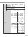
PoE Industrial Ethernet Extender IVC-2004PT User’s Manual Trademarks Copyright © PLANET Technology Corp. 2014 Contents are subject to revision without prior notice. PLANET is a registered trademark of PLANET Technology Corp. The information in this manual is subject to change without notice. All other trademarks belong to their respective owners. Disclaimer PLANET Technology does not warrant that the hardware will work properly in all environments and applications, and makes no warranty and representation, either implied or expressed, with respect to the quality, performance, merchantability, or fitness for a particular purpose. PLANET has made every effort to ensure that this User’s Manual is accurate; PLANET disclaims liability for any inaccuracies or omissions that may have occurred. Information in this User’s Manual is subject to change without notice and does not represent a commitment on the part of PLANET. PLANET assumes no responsibility for any inaccuracies that may be contained in this User’s Manual. PLANET makes no commitment to update or keep current the information in this User’s Manual, and reserves the right to make improvements to this User’s Manual and/or to the products described in this User’s Manual, at any time without notice. FCC Warning This equipment has been tested and found to comply with the regulations for a Class A digital device, pursuant to Part 15 of the FCC Rules. These limits are designed to provide reasonable protection against harmful interference when the equipment is operated in a commercial environment. This equipment generates, uses, and can radiate radio frequency energy and, if not installed and used in accordance with this user’s guide, may cause harmful interference to radio communications. Operation of this equipment in a residential area is likely to cause harmful interference, in which case the user will be required to correct the interference at his own expense. CE Mark Warning This is a Class A product. In a domestic environment, this product may cause radio interference, in which case the user may be required to take adequate measures. WEEE Warning To avoid the potential effects on the environment and human health as a result of the presence of hazardous substances in electrical and electronic equipment, end users of electrical and electronic equipment should understand the meaning of the crossed-out wheeled bin symbol. Do not dispose of WEEE as unsorted municipal waste and have to collect such WEEE separately. Revision PLANET PoE Industrial Ethernet Extender User's Manual For Model: IVC-2004PT Rev 2.0 (March, 2014) Part No.: 2350-AH0350-003 Table Of Contents 1.Introduction............................................................................... 5 1.1Checklist............................................................................. 5 1.2 Ethernet over VDSL2 Bridge Description................................ 5 1.3 Key Features....................................................................... 7 1.4 Specifications...................................................................... 8 2. Hardware Description.................................................................11 2.1 Front Panel........................................................................11 2.1.1 LED Indicators for IVC-2004PT...................................12 2.1.2 DIP Switch Indication................................................13 2.2 The Upper Panel.................................................................14 3.Installation ..............................................................................15 3.1 Installing PoE Industrial Ethernet Extender – IVC-2004PT.......15 3.2 IVC-2004PT BNC / RJ-11 Proper Connection.........................16 3.3 IVC-2004PT Application Connection......................................17 3.4 Wiring the Power Inputs......................................................20 3.5 Wiring the Fault Alarm Contact............................................21 3.6 Mounting Installation...........................................................22 3.6.1 DIN-Rail Mounting.....................................................22 3.6.2 Wall Mount Plate Mounting........................................24 4.Troubleshooting.........................................................................25 5.FAQ.........................................................................................26 1.Introduction 1.1Checklist Check the contents of your package for the following parts: zz PoE Industrial Ethernet Extender x 1 zz User’s Manual x 1 zz DIN Rail Kit zz Wall Mount Kit If any of these items are missing or damaged, please contact your dealer immediately; if possible, retain the carton including the original packing material, and use them again to repack the product in case there is a need to return it to us for repair. 1.2 Ethernet over VDSL2 Bridge Description PLANET's state-of-the-art Ethernet-over-VDSL2 products are based on two core networking technologies: Ethernet and VDSL2 (Very-highdata-rate Digital Subscriber Line 2). This technology offers the absolute fastest possible data transmission speeds over the existing copper telephone lines or coaxial cables without the need for rewiring. The IVC-2004PT PoE Industrial Ethernet Extender has a switching architecture with 4 PoE of RJ-45 10/100Mbps ports and Asymmetric or Symmetric Ethernet over VDSL port (Asymmetric means upstream and downstream rate are not the same and Symmetric means upstream and downstream rate are similar) – the VDSL port can be RJ-11 or BNC Connector. The IVC-2004PT can set to Master or Slave mode via a DIP switch. When IVC-2004PT (RJ-11) is connected with another IVC-2004PT device, the performance will go up to 99/63Mbps for asymmetric data rate within 200m and go up to 28/2Mbps at 1.4km. The IVC-2004PT (BNC) performance is up to 99/65Mbps for asymmetric data rate within 200m and up to 31/4Mbps at 2.4km. This capability is ideal for use as an Ethernet extender for your existing Ethernet network. 5 With 4 PoE interfaces, the IVC-2004PT will be ideal for small businesses and workgroups requiring to deploy the PoE for the wireless access points, IP-based surveillance camera or IP phones in any places easily, efficiently and cost-effectively. The IVC-2004PT PoE Industrial Ethernet Extender with the IP-30 aluminum metal shape is designed for easy deployment in Heavy Industrial demanding environments. PLANET PoE Industrial Ethernet Extender provides a lower cost replacement and smooth migration for the existing Long Reach Ethernet (LRE) networks. The cable specifications of the connection are listed as follows: zz 10Base-T, Category 3, 4 or 5 UTP zz 100Base-TX, Category 5, 5e or 6 UTP zz Ethernet over VDSL2, Twisted-pair Telephone Wires zz Ethernet over VDSL2, Coaxial Cable Note 6 Slave device (CPE) must be connected to Master device (CO) through the telephone wire or coaxial cable. It does not allow connection like Master to Master or Slave to Slave. To check whether the IVC-2004PT is connected to Master or Slave, please refer to section 2.1.2 for more details. 1.3 Key Features The PoE Industrial Ethernet Extender provides the following key features: zz 4-port IEEE 802.3af Power over Ethernet Standard zz Each PoE port provides 15.4 watts zz Compatible with IVC-2002, VC-201A and VC-202A (17a Profile) zz Cost-effective VDSL2 Master / Slave bridge solution via DIP Switch zz Selectable BNC and RJ-11 mode for the data transmission zz -40 to 75 degrees C operating temperature zz Redundant Power Design: 24V or 48V DC, redundant power with polarity reverse protect function zz IP30 aluminum metal case protection zz Defines Asymmetric (Band Plan 998) and Symmetric band plans for the transmission of Upstream and Downstream signals zz Complies with IEEE 802.3, IEEE 802.3u and IEEE 802.3x standards zz DMT (Discrete Multi-Tone) line coding zz Half duplex back pressure and IEEE 802.3x full duplex fause frame flow control zz Supports up to 1536 bytes packet size, 802.1Q VLAN tag transparent zz Integrated address look-up engine, supporting 2K absolute MAC addresses zz VDSL2 Stand-alone transceiver for simple bridge modem application zz Selectable Target Band Plan and Target SNR Margin zz Support extensive LED indicators for network diagnostics zz DIN Rail and Wall-mount design 7 1.4 Specifications Product IVC-2004PT Hardware Specifications 10/100 Base-TX 4 x RJ-45, Auto-Negotiation and Auto-MDI/MDI-X Ports PoE 4 x PoE (Port1 ~ Port4) VDSL 1 x RJ-11, female Phone Jack 1 x BNC, female connector DIP Switch 4 position DIP switch Functionality *1 Master / Slave mode select Selectable BNC and RJ-11 mode Selectable target Band Plan Selectable target SNR mode Encoding VDSL-DMT - ITU-T G.997.1 - ITU-T G.993.1 VDSL - ITU-T G.993.2 VDSL2 (Profile 17a Support) LED Indicators P1 (Green) P2 (Green) Fault (Green) Master (Green) and Slave (Green) ACT (Green) Sync. (Green) PoE ( Orange) Power Over Ethernet 8 PoE Standard IEEE 802.3af Power over Ethernet / PSE PoE Type End-Span PoE Power Input 24V or 48V DC power input source PoE Power Output 48V DC Per Port, 350mA . Max. 15.4 watts PoE Pin Assignment 1/2(+), 3/6(-) Ethernet •10Base-T: 2-pair UTP Cat.3,4,5 up to 100m (328ft) •100Base-TX: 2-pair UTP Cat.5, 5e, 6 up to 100m (328ft) VDSL (RJ-11) Twisted-pair telephone wires (AWG24 or better) up to 1.4km BNC 50 ohm: RG58A/U, RG58C/U, RG58/U and 75 ohm: RG6 (Distance 2.4km) Cabling Asymmetric Mode VDSL (RJ-11) 200m -> 99/63Mbps 400m -> 91/48Mbps 600m -> 71/32Mbps 800m -> 53/18Mbps 1000m -> 38/8Mbps 1200m -> 33/5Mbps 1400m -> 28/2Mbps Performance *2 (Downstream / Upstream) BNC 200m -> 99/65Mbps 400m -> 99/64Mbps 600m -> 97/59Mbps 800m -> 94/51Mbps 1000m -> 84/45Mbps 1200m -> 73/37Mbps 1400m -> 61/28Mbps 1600m -> 54/20Mbps 1800m -> 48/13Mbps 2000m -> 39/9Mbps 2200m -> 35/6Mbps 2400m -> 31/4Mbps Symmetric Mode VDSL (RJ-11) BNC 200m -> 91/99Mbps 400m -> 74/79Mbps 600m -> 54/51Mbps 800m -> 38/34Mbps 1000m -> 27/21Mbps 1200m -> 24/15Mbps 1400m -> 21/10Mbps 200m -> 95/99Mbps 400m -> 92/97Mbps 600m -> 81/82Mbps 800m -> 71/70Mbps 1000m -> 60/57Mbps 1200m -> 50/44Mbps 1400m -> 42/33Mbps 1600m -> 37/27Mbps 1800m -> 29/22Mbps 2000m -> 23/21Mbps 2200m -> 19/17Mbps 2400m -> 19/13Mbps 9 Dimensions (H x W x D) 135mm x 87.8mm x 50mm Weight 631g Power Requirements 24V or 48V DC for PoE Devices Redundant power with polarity reverse protection function Power Consumption / Dissipation 66.4 watts / 226BTU max. (PoE) 5.64 watts / 19.24BTU (non-PoE) Installation DIN Rail Kit and Wall-mount Ear Standard Conformance Stability Testing IEC60068-2-32 (Free Fall) IEC60068-2-27 (Shock) IEC60068-2-6 (Vibration) Operating Temperature -40 ~ 75ºC Storage Temperature -40 ~ 85ºC Operating Humidity 10% to 90%, relative humidity, non-condensing Storage Humidity 10% to 90%, relative humidity, non-condensing Regulation Compliance FCC Part 15 Class A, CE Standards Compliance IEEE 802.3 10Base-T IEEE 802.3u 100Base-TX IEEE 802.3af Power over Ethernet IEEE 802.3x Full duplex pause frame flow control ITU-T 1. G.997.1 2. G.993.1 VDSL 3. G.993.2 VDSL2 (Profile 17a) *1.BNC and RJ-11 mode must switch to the same position for Master and Slave. Otherwise, it may cause unstability. *2.The actual data rate will vary on the quality of the copper wire and environment factors. 10 2.Hardware Description zz IVC-2004PT The IVC-2004PT provides 4 RJ-45 with PoE, 1 RJ-11 and 1 BNC port for network line connection. The 4 RJ-45 ports come with two different running speeds – 10Mbps and 100Mbps. It will distinguish the speed of incoming connection automatically. This section describes the hardware features of the PoE Industrial Ethernet Extender. For easier control of the PoE Industrial Ethernet Extender, familiarize yourself with its display indicators and ports. Front panel illustrations in this chapter display the unit LED indicators. Before connecting any network device to the PoE Industrial Ethernet Extender, read this chapter carefully. 2.1 Front Panel The unit’s front panel provides a simple interface monitoring the PoE Industrial Ethernet Extender. zz IVC-2004PT Front Panel P1 P2 FAULT Slave Master Sync. ACT ON OFF 1 2 3 4 ON Slave BNC Asymm 6dB Master RJ-11 Symm 9dB BNC VDSL RJ-11 LNK/ ACT 1 PoE In-Use 2 3 4 LNK/ACT PoE In-Use IVC-2004PT Figure 2-1: IVC-2004PT Front Panel 11 zz 2.1.1 LED Indicators for IVC-2004PT The diagnostic LEDs on the front panel provide the operating status of individual port. zz System LED Color Function P1 Green Light Indicates power 1 has power. P2 Green Light Indicates power 2 has power. Fault Green Light Indicates either power 1 or power 2 has no power. Light Indicates that the VDSL link is established Blink Indicates that the VDSL link is actively sending or receiving data over that port. Light Indicates that the VDSL link is established Fast Blink Indicates that the VDSL link is at training status (about 10 seconds). Slow Blink Indicates that the VDSL link is at idle status. zz VDSL / BNC LED ACT Sync Color Green Green Function Master Green Light Indicates the VDSL Bridge is running at Master mode. Slave Green Light Indicates the VDSL Bridge is running at Slave mode. zz 10/100Base-TX with PoE Port LED LNK/ ACT PoE In-Use 12 Color Green Function Light Indicates that the port is linked up. Blink Indicates that the Extender is actively sending or receiving data over that port. Off Indicates that the port is linked down. Orange Light Indicates the port is providing 48V DC in-line power. (1-4 ports). zz 2.1.2 DIP Switch Indication The PoE Industrial Ethernet Extender provides 4 selective transmission modes. By switching the transmission mode, you can obtain the best transmission mode to suit the phone line or BNC quality of distance connectivity. The following is the summary table of transmission setting, bandwidth and distance extensibility tested for AWG 24 (0.5mm) twisted-pair without noise and cross talk. DIP Switch DIP-1 DIP-2 DIP-3 DIP-4 Function Mode Link Type Band Plan SNR OFF Master RJ-11 Symm 9dB ON (default) Slave BNC Asymm 6dB zz Master / Salve tMaster (Central Office) – In the Master device mode, usually the Master device will be located at the data center of ISP or enterprise to link to the backbone. tSlave (Customer Premises Equipment) – In the Slave device mode, usually the Slave device will be located at branch office, home or remote side as the long-reach data receiver. The Slave also can be connected to the PC, IP Camera or Wireless Access Point. Note When the PoE Industrial Ethernet Extender operates at Slave mode, the DIP switch 2, 3 and 4 are non-functional. zz Link Type tBNC mode allows IVC-2004PT to connect and transfer data by using BNC cable tRJ-11 mode allows IVC-2004PT to connect and transfer data by using Telephone Wire 13 zz Band Plan tUser can switch the Band Plan either Symmetric or Asymmetric by their own. When Symmetric is selected, it provides better upstream performance. When Asymmetric is selected, it provides better downstream performance. Please refer to the above table for details. zz Target SNR (Signal Noise Ratio) Margin tWhen fixed SNR margin is selected, the system will maintain the SNR margin at 9 dB across all usable loop length. Note By default setting, DIP 4 switch is set at “ON” position and operate as “Slave”. To operate as “Master”, please set DIP 1 switch to “OFF” position. Adjust other DIP switch settings according to different network application demands Please power off the PoE Industrial Ethernet Extender before making any transmission mode adjustment. 2.2 The Upper Panel The upper panel of the PoE Industrial Ethernet Extender consists of one terminal block connector within two DC power inputs. Figure 2-2 shows the upper panel of the PoE Industrial Ethernet Extender. V1- V1+ PWR1 V2- V2+ Fault PWR2 Input DC 24V / 48V Figure 2-2 PoE Industrial Ethernet Extender Upper Panel. 14 3.Installation 3.1Installing PoE Industrial Ethernet Extender – IVC2004PT The PoE Industrial Ethernet Extender does not require any software configuration. Users can immediately use any feature of this product simply by attaching the cables and powering on. The PoE Industrial Ethernet Extender has some limitation as mentioned below: IVC-2004PT: The device is used for Point-to-Point connection only (Master device to Slave device) and has equipped with one RJ-11 and one BNC connector for VDSL2 network connection. Telephone Wire: Depending on the quality of telephone line, the maximum distance of RJ-11 segment is 1.4km (4593ft) with AWG 24 telephone wires. Coaxial: Depending on the quality of coaxial cable, the maximum distance of BNC segment is 2.4km (7874ft) with 5C type of coaxial cable. The link distances and performance will vary on the quality of telephone wire and coaxial cable. 15 3.2 IVC-2004PT BNC / RJ-11 Proper Connection PLANET PoE Industrial Ethernet Extender has a DIP switch which can adjust to be Master or Slave mode. As to connection of two PLANET PoE Industrial Ethernet Extenders, one must be Master (CO) mode and the other one must be Slave (CPE) mode. Please refer to the following Figure 3-1 chart. PoE Industrial Ethernet Extender does not allow connecting BNC and RJ-11 at the same time. Note P1 ON P2 FAULT Slave Master OFF ON Sync. ACT BNC Coaxial Cable Connections 2.4km Max. BNC Slave BNC Asymm 6dB RJ-11 OFF Master RJ-11 Symm 9dB VDSL2 VDSL DIP 2 must switch to the BNC mode No Connection RJ-11 PoE IP camera 1 2 3 4 1 2 3 4 ON Master RJ-11 Symm 9dB 1 2 3 4 OFF ON ON Slave BNC Asymm 6dB ON Master RJ-11 Symm 9dB 1 2 3 4 ON Slave BNC Asymm 6dB Ethernet Switch PoE LNK/ ACT 1 PoE In-Use RJ-45 Connections 100m (328ft) Max. RJ-45 Connections 100m (328ft) Max. 2 3 4 LNK/ACT PoE In-Use IVC-2004PT Slave / IVC-2002 Master / IVC-2004PT P1 ON P2 FAULT Slave Master OFF ON OFF Master RJ-11 Symm 9dB BNC 1 2 3 4 ON 1 2 3 4 Slave BNC Asymm 6dB Slave BNC Asymm 6dB RJ-11 OFF 1 2 3 4 ON ON Sync. ACT Master RJ-11 Symm 9dB ON 1 2 3 4 ON Slave BNC Asymm 6dB Master RJ-11 Symm 9dB No Connection BNC VDSL RJ-11 PoE IP camera VDSL2 Telephone Wire Connections 1.4km Max. PoE LNK/ ACT RJ-45 Connections 100m (328ft) Max. Ethernet Switch 1 DIP 2 must switch to the RJ-11 mode PoE In-Use 2 RJ-45 Connections 100m (328ft) Max. 3 4 LNK/ACT PoE In-Use IVC-2004PT Master / IVC-2004PT Slave / IVC-2002 VDSL2 VDSL2 Coaxial Cable VDSL2 VDSL2 Telephone Wire PoE 100Base-TX UTP with PoE 100Base-TX UTP Figure 3-1: Industrial Ethernet Extender BNC and RJ-11 Connection Chart 16 3.3 IVC-2004PT Application Connection Two PoE Industrial Ethernet Extenders could be used to link two different Area networks. Through the normal telephone line or coaxial cable, it could set up to 99/63Mbps (RJ-11) or 99/65Mbps (BNC) for asymmetric backbone. PoE 100Base-TX UTP with PoE 100Base-TX UTP VDSL2 VDSL2 PoE PoE IP Camera PoE NVR PoE IP Camera VDSL2 Coaxial or Phone Wire PoE IVC-2004PT PoE Wireless AP IVC-2004PT PoE PoE IP Phone LAN 1 * BNC: 2.4km RJ-11: 1.4km LAN 2 Figure 3-2: IVC-2004PT BNC and RJ-11 Connection With 4 PoE, in-line power interfaces, the PoE Industrial Ethernet Extender can build a power central-controlled IP phone system, IP camera system, and AP group for the enterprise. For instance, 4 cameras / APs can be easily installed around the corner in the company for surveillance demands or build a wireless roaming environment in the offices. Without the power-socket limitation, it makes the installation of cameras or WLAN AP easier and more efficient 17 Data+Power PoE PoE 100Base-TX UTP with PoE DC Power Line (DC) Telephone wire PoE IP Camera 2.4GHz 802.11n N 24V / 48V DC Power Input IVC-2004PT DC DIN-Rail Power Supply Data+Power PoE PoE VoIP ATA PoE PoE N N Phone PoE VoIP Phone PoE Wireless AP Figure 3-3: IVC-2004PT PoE Connection The IVC-2004PT temperature range is from -40 to 75 degrees C which can handle any harsh environment and places. It is also compatible with PLANET IVC-2002, VC-201A and VC-202A, without spending extra cost to deploy a new local Internet in an apartment, hotel, campus and hospitality environment. The original network structure can be used to re-deploy with our latest PLANET IVC-2004PT. For example, MC-700, MC-1500 and MC-1500R chassis with VC-201A and VC-202A inside can be set as CPE (Customer Premises Equipment) mode which is placed in the wiring center (MDF room). Besides, connecting an IVC-2004PT extender in Master mode can be had by using telephone line or coaxial cable. 18 Switch 1.4km 2.4km IVC-2004PT Master VDSL2 IVC-2004PT Master VDSL2 VC-202A/VC-201A CPE+ MC-700 Chassis PoE PoE IP Camera PoE PoE IP Camera VDSL2 Control Center 2.4km PoE PoE IVC-2004PT Master PoE PoE IP Camera PoE IP Camera PoE IP Camera Harbor Steel Factory PoE PoE PoE IP Camera Railway 100Base-TX UTP with PoE 100Base-TX UTP VDSL2 VDSL2 Coaxial Cable VDSL2 VDSL2 Telephone Wire Figure 3-4: IVC-2004PT Application Topology To decide where to put the IVC-2004PT, you must ensure: tIt is accessible and cables can be connected easily. tCabling is away from sources of electrical noise such as radios, transmitters and power lines and fluorescent lighting fixtures tWater or moisture must be avoided. tAir Flow around the unit and through the vents in the side of the case is not restricted (A minimum of 25mm inch clearance is recommended.). To prolong the operational life of your units: tDo not place objects on top of any unit or stack. 19 3.4 Wiring the Power Inputs The 6-contact terminal block connector on the top panel of PoE Industrial Ethernet Extender is used for two DC redundant power inputs. Please follow the steps below to insert the power wire. 1.Insert positive / negative DC power wires into contacts 1 and 2 for POWER 1, or 5 and 6 for POWER 2. V1- V1+ PWR1 V1- V1+ Note 20 V2- V2+ Fault PWR2 Input DC 24V/48V V2- V2+ Must input 24V or 48V DC power source to make PoE function workable. 2.Tighten the wire-clamp screws for preventing the wires from loosening. 1 2 Power 1 - 3 4 Fault + 5 6 Power 2 - + 3.5 Wiring the Fault Alarm Contact The fault alarm contacts are in the middle of the terminal block connector as the picture shows below. Inserting the wires, the PoE Industrial Ethernet Extender will detect the fault status of the power failure and then forms an open circuit. The following illustration shows an application example for wiring the fault alarm contacts. Insert the wires into the fault alarm contacts 21 Note 1.The wire gauge for the terminal block should be in the range of 12 to 24 AWG. 2.Alarm relay circuit accepts up to 30V, max. 3A currents. 3.6 Mounting Installation This section describes how to install the PoE Industrial Ethernet Extender and make connection to it. Please read the following topics and perform the procedures in the order being presented. Note In the installation steps below, this Manual uses IGS-801 (PLANET 8-port Industrial Gigabit Switch) as an example. However, the steps for PLANET Industrial Switch and Industrial Media Converter are similar. zz 3.6.1 DIN-Rail Mounting The DIN-Rail is screwed on the PoE Industrial Ethernet Extender when out of factory. Please refer to the following figures to hang the PoE Industrial Ethernet Extender on track. 22 1 2 Step 1: Lightly press the button of the DIN-Rail to put it onto the track. Step 2: Check whether the DIN-Rail is tightly on the track. Step 3: Please refer to the following procedures to remove the PoE Industrial Ethernet Extender from the track. 1 2 Step 4: Lightly press the button of the DIN-Rail to remove it from the track. 23 zz 3.6.2 Wall-mount Plate Mounting To install the PoE Industrial Ethernet Extender on the wall, please follow the instructions described below. Step 1:Remove the DIN-Rail from the PoE Industrial Ethernet Extender; loose the screws to remove the DIN-Rail. Step 2: Place the wall-mount plate on the rear panel of the PoE Industrial Ethernet Extender. Step 3: Use the screws to screw the wall-mount plate on the PoE Industrial Ethernet Extender. Step 4: Use the hook holes at the corners of the wall-mount plate to hang the PoE Industrial Ethernet Extender on the wall. Step 5: To remove the wall-mount plate, reverse the above steps. 24 4. Troubleshooting SYMPTOM: VDSL LNK LED does not light after wire is connected to the VDSL port. CHECKPOINT: 1.Verify the length of the wires connected between two IVC-2004PT extenders not more than 2.4km for BNC and 1.4km for RJ-11 connections. Please also try to set the DIP switch of the IVC-2004PT to the other SNR mode. 2.Please note that you must use one IVC-2004PT in Master mode and the other IVC-2004PT in Slave mode. SYMPTOM: TP LED does not light after cable is connected to the port. CHECKPOINT: 1.Verify you are using the Cat.5, 5e or 6 cables with RJ-45 connector to connect to the port. 2.If your device (like LAN card) supports Auto-Negotiation, please try to modify at a fixed speed of your device manually. 3.Check whether the extender’s and the connected device’s power are “ON”. 4.Check whether the cables are firmly seated in its connectors in the switch and in the associated device. 5.Check whether the connecting cables are good. 6. Check whether the power adapter is functional, including the connecting device. SYMPTOM: VDSL sometimes will re-chain and not stable. CHECKPOINT: 1. Verify what connection type of the cable is using, BNC or RJ-11 cable. 2.Check whether the Master (CO) and Slave (CPE) DIP-2 is switched to the same and correct mode. 25 5. FAQ Q1: What is the IVC-2004PT power input? A1: 24V or 48V DC for PoE function. Q2: What is VDSL2? A2: VDSL2 (Very High-Bit-Rate Digital Subscriber Line 2), G.993.2 is the newest and most advanced standard of xDSL broadband wire line communications. Designed to support the wide deployment of Triple Play services such as voice, data, high definition television (HDTV) and interactive gaming, VDSL2 enables operators and carrier to gradually, flexibly, and cost-efficiently upgrade the existing xDSL-infrastructure. Q3: What is the best distance for IVC-2004PT? A3: n order to guarantee the stability and better quality of network, we suggest the distance within 1.4 kilometers is the best for RJ-11 connection and 2.4 kilometers for BNC Connection. Q4: What is the best data rate for IVC-2004PT? A4: Link Type & RJ-11 (Telephone Wire) Distance 200m 1400m DIP Mode 200m Asymmetric 99/63Mbps 28/2Mbps 99/65Mbps 31/4Mbps Symmetric 91/99Mbps 21/10Mbps 95/99Mbps 19/13Mbps BNC (Coaxial Cable) 2400m Q5: Is IVC-2004PT compatible with VC-201A / VC-202A? A5: Yes, IVC-2004PT (profile 17a) and VC-201A / VC-202A (profile 17a) are based on ITU-T G.993.2 VDSL2 with the same profile; so far they are compatible with each other. 26 Q6: What is SNR and what’s the effect? A6: In analog and digital communications, Signal-to-Noise Ratio, often written as SNR, is a measure of signal strength relative to background noise. The ratio is usually measured in decibels (dB). In digital communications, the SNR will probably cause a reduction in data speed because of frequent errors that require the source (transmitting) computer or terminal to resend some packets of data. SNR measures the quality of a transmission channel over a network channel. The greater the ratio, the easier it is to identify and subsequently isolate and eliminate the source of noise. Generally speaking, the higher SNR value gets, the better the line quality, but lower performance. Q7: What is band plan and what’s the effect? A7: VDSL2 defines multiple band plans and configuration modes (profiles) to allow asymmetric and symmetric services in the same binder (by designated frequency bands) for the transmission of upstream and downstream signals. User has the ability to select fixed band plan. The selection of Symmetric provides better downstream performance, while the selected Asymmetric offers better upstream performance. 27 EC Declaration of Conformity For the following equipment: *Type of Product: Industrial Ethernet Extender with 4-Port PoE (1 BNC / RJ-11 + 4-Port 10/100TX *Model Number: PoE -17a Profile, -40~75 Degree C) IVC-2004PT * Produced by: Manufacturer‘s Name : Manufacturer‘s Address: Planet Technology Corp. 10F., No.96, Minquan Rd., Xindian Dist., New Taipei City 231, Taiwan (R.O.C.) is herewith confirmed to comply with the requirements set out in the Council Directive on the Approximation of the Laws of the Member States relating to Electromagnetic Compatibility Directive on (2004/108/EC). For the evaluation regarding the EMC, the following standards were applied: EN 55022 EN 61000-3-2 EN 61000-3-3 EN 55024 (Class A: 2006 + A1:2007) (2006 + A2:2009) (2008) (1998 + A1: 2001 + A2:2003) (2008) (2008) (2004) (2005) (2008) (2009) (2004) IEC 61000-4-2 IEC 61000-4-3 IEC 61000-4-4 IEC 61000-4-5 IEC 61000-4-6 IEC 61000-4-8 IEC 61000-4-11 Responsible for marking this declaration if the: Manufacturer Authorized representative established within the EU Authorized representative established within the EU (if applicable): Company Name: Planet Technology Corp. Company Address: 10F., No.96, Minquan Rd., Xindian Dist., New Taipei City 231, Taiwan (R.O.C.) Person responsible for making this declaration Name, Surname Kent Kang Position / Title : Product Manager Taiwan Place 22 Oct., 2010 Date Legal Signature PLANET TECHNOLOGY CORPORATION e-mail: [email protected] http://www.planet.com.tw 10F., No.96, Minquan Rd., Xindian Dist., New Taipei City, Taiwan, R.O.C. Tel:886-2-2219-9518 Fax:886-2-2219-9528